SIDACtor Protection Thyristors
®
Broadband Optimized™
RoHS
SDP Biased Series
Description This new SIDACtor series provides over voltage protection for applications such as VDSL2, ADSL2+, and 1000BaseT with minimal affect on the data signal. This latest silicon design innovation results in a capacitive loading characteristic that is compatible with these high bandwidth applications. This QFN package is a surface mount solution offered with a surge capability that meets or exceeds most worldwide inter-building standards and recommendations for lightning surge withstand capability of secondar y protectors.
Agency Approvals
Agency Agency File Number E133083
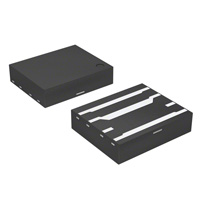
Features & Benefits • RoHS compliant • QFN (Quad Flatpak No-lead) surface mount package • Low insertion loss
1 2 3 4 8 7 6 5
• Crowbarring speed of nanoseconds • Teccor branded SIDACtor technology • Balanced longitudinal load capacitance • Balanced OV protection
Pinout Designation
Tip in - Bias Ground Ring in Tip out + Bias Ground Ring out
• Low log linear voltage dependent capacitance • Bidirectional transient voltage protection Protection Solution for • YD/T 950
Schematic Symbol
• IEC 61000-4-5 • ITU K.20/21 Basic Level • ITU K.20/21 Enhanced Level • TIA-968-A
+Bias -Bias
Tip Ground Ring
• YD/T 993 • YD/T 1082 • GR 1089 Intra-building • GR 1089 Inter-building
Electrical Characteristics
VDRM@ IDRM=5µA Volts Min 6 58 65 75 90 120 170 220 275 320 VS@10 0V/µS Volts Max 25 77 88 98 130 160 220 30 0 350 400 IH mAmps Min 50 150 150 150 150 150 150 150 150 150 IS mAmps 80 0 80 0 80 0 80 0 80 0 80 0 80 0 80 0 80 0 80 0 IT@VT Amps 2.2 2.2 2.2 2.2 2.2 2.2 2.2 2.2 2.2 2.2 VT@IT=2.2 amp Volts Max 8 8 8 8 8 8 8 8 8 8
Part Number
Marking
Capacitance @1MHz @ 2V bias
SDP0080Q38CB SDP0640Q38CB SDP0720Q38CB SDP0900Q38CB SDP1100Q38CB SDP1300Q38CB SDP1800Q38CB SDP2600Q38CB SDP3100Q38CB SDP3500Q38CB
SDP-8C SDP06C SDP07C SDP09C SDP10C SDP13C SDP18C SDP26C SDP31C SDP35C
See Capacitance vs. Bias Voltage Graph
• All measurements are made at an ambient temperature of 25°C. IPP applies to -40°C through +85°C temperature range. • Listed SIDACtor devices are bidirectional. All electrical parameters and surge ratings apply to for ward and reverse polarities. • SDP Biased Series 1 SIDACtor® Protection Thyristor Datasheet www.littelfuse.com ©2008 Littelfuse
�SIDACtor Protection Thyristors
®
Broadband Optimized™
50/60 Hz Ratings
Parameter Name Test Conditions 0.5s 1s 2s 5s 30s 900s Value 6.5 4.6 3.4 2.3 1.3 0.73 Units
ITSM Maximum non-repetitive on-state current, 50/60 Hz
A
Surge Ratings
IPP Series 2x10µs Amps Min C 500 1.2x50µs/8x20µs Amps Min 400 10x700/5x310µs Amps Min 200 10x1000µs Amps Min 100 ITSM 600VRMS 1 cycle ARMS Min 45
Note: The lightning surge may be repeated after the device returns to its initial conditions. The device must initially be in thermal equilibrium with -40°C ≥ TJ ≥150°C
Thermal Considerations
Package Symbol TJ TSTG
5x6 QFN
Parameter Junction Temperature Storage Temperature Range Thermal Resistance: Junction to Ambient
Value -65 to +150 -65 to +150 100
Unit °C °C °C/ W
RθJA
Note : The device must initially be in thermal equilibrium with -40°C ≥TJ ≥ 150°C
V-I Characteristics
+I
Capacitance vs. Voltage*
40
35
IT
Capacitance (pF)
30
IS IH IDRM +V VT VDRM VS
0V 5V 24V 50V
3.3V 12V 30V
25
20
-V
15
10
5
-I
0 0.1
1 Line Voltage
10
100
* bias voltage must be lower than VDRM
SDP Biased Series
2 SIDACtor® Protection Thyristor Datasheet
www.littelfuse.com ©2008 Littelfuse
�SIDACtor Protection Thyristors
®
Broadband Optimized™
Normalized VS Change vs. Junction Temperature
14
Normalized DC Holding Current vs. Case Temperature
2.0 1.8 1.6 1.4 1.2 1.0 0.8 0.6 0.4 -40 -20 0 40 60 80 100 120 140 160
Percent of VS Change – %
12 10
IH
8 6 4 2 0 -4 -6 -8 -40 -20 0 20 40 60 80 100 120 140 160
IH (TC = 25 ˚C)
25 ˚C
25 ˚C
Ratio of
Junction Temperature (TJ) – ˚C
Case Temperature (TC) – ˚C
Soldering Parameters
Reflow Condition - Temperature Min (Ts(min)) Pre Heat - Temperature Max (Ts(max)) - Time (min to max) (ts) Average ramp up rate (Liquidus Temp (TL) to peak) TS(max) to TL - Ramp-up Rate Reflow - Temperature (TL) (Liquidus) - Temperature (tL) Pb – Free assembly (see Figure1) 150°C 200°C 60 – 180 secs 3°C/second max 3°C/second max 217°C 60 – 150 seconds 260+0-5 °C 20 – 30 seconds 6°C/second max 8 minutes max 260°C High Temperature Voltage Blocking Temperature Cycling
Peak Temperature (TP) Time within 5°C of actual peak Temperature (tp) Ramp-down Rate Time 25°C to peak Temperature (TP) Do not exceed
Environmental Specifications
MIL -STD-750: Method 1040, Condition A 80% min VDRM (VAC-peak), 150°C, 504 hours MIL -STD-750: Method 1051 -65°C to 150°C, 15-minute dwell, 100 cycles EIA/JEDEC: JESD22-A101 52VDC, 85°C, 85%RH, 1008 hours MIL -STD-750: Method 1031 150°C, 1008 hours -65°C, 1008 hours
Physical Specifications
Terminal Material Terminal Finish Body Material Copper Alloy 100% Matte Tin Plated UL recognized epoxy meeting flammability classification 94V-0
Biased Temperature & Humidity High Temp. Storage Low Temp. Storage Thermal Shock
MIL -STD-750: Method 1056 0°C to 100°C, 5-minute dwell, 10-second transfer, 10 cycles Autoclave EIA/JEDEC: JESD22-A102 (Pressure Cooker Test) 121°C, 100%RH, 2atm, 168 hours Resistance to MIL -STD-750: Method 2031 Solder Heat 260°C, 10 seconds
SDP Biased Series
3 SIDACtor® Protection Thyristor Datasheet
www.littelfuse.com ©2008 Littelfuse
�SIDACtor Protection Thyristors
®
Broadband Optimized™
Dimensions
A
5
6
7
8
Dimension A
Inches Min 0.187 0.226 0.054 0.165 0.027 0.011 0.047 0.032 0.027 0.100 Typ 0.197 0.236 0.059 0.168 0.030 0.014 0.050 0.035 0.030 0.103 Max 0.207 0.246 0.064 0.171 0.033 0.017 0.053 0.038 0.033 0.106 Min 4.745 5.745 1.374 4.199 0.686 0.279 1.194 0.800 0.686 2.540
Millimeters Typ 5.000 6.000 1.500 4.275 0.762 0.356 1.270 0.876 0.762 2.616 Max 5.253 6.253 1.628 4.351 0.838 0.432 1.346 0.953 0.838 2.692
B
D I
H
B C
J
D
E
4
3
2
G
1
E
F
PIN 1 INDICATOR
F G H I J
PIN 1 & 8: TIP CONNECTIONS PIN 2: BIAS (-)
C
PIN 3 & 6: GROUND CONNECTIONS PIN 4 & 5: RING CONNECTION
F (ref)
G (ref)
PIN 7: BIAS (+)
Part Numbering System
Part Marking System
SDP xxx 0 Q38 C B
Biased
FAMILY SDP: SIDACtor DSL Protector MEDIAN VOLTAGE RATING C: 10x1000 100A PACKAGE Q38: QFN 5x6 0 = Single protector
XXXXXX First Line: Part number Second Line: Date code
XXXXX
Packaging Options
Package Type QFN Description 5x6x1.5 Packaging Quantity 4,000 Added Suffix RP Industry Standard 12mm Embossed Carrier Tape & Reel
SDP Biased Series
4 SIDACtor® Protection Thyristor Datasheet
www.littelfuse.com ©2008 Littelfuse
�SIDACtor Protection Thyristors
®
Broadband Optimized™
Tape and Reel Specifications
ITEM
N B
REEL OUTLINE
C A D W1
END
CARRIER TAPE
COVER TAPE
START
TRAILER 160mm MIN
LEADER 400mm MIN
TAPE LEADER AND TRAILER
D0 T
PIN 1 MARK THIS SIDE
P0 P2
D1
CARRIER TAPE
E1 F
W0 K0
COVER TAPE
E2 W
A B C D N W1 A0 B0 A1 B1 D0 D1 E1 E2 F K0 P0 P1 P2 T W W0
P1
A0
B0
CARRIER TAPE DIMENSIONS
Inches Min Typ Max Reel Diameter N/A 12.992 Drive Spoke Width 0.059 N/A Arbor Hole Diameter 0.504 0.531 Drive Spoke Diameter 0.795 N/A Hub Diameter 1.969 N/A Reel Inner Width at Hub 0.488 0.567 Pocket Width at bottom 0.204 0.208 0.212 Pocket Length at bottom 0.244 0.248 0.252 Pocket Width at opening 0.212 Pocket Length at opening 0.252 Feed Hole Diameter 0.059 0.061 0.063 Pocket Hole Diameter 0.059 0.063 N/A Feed hole position 1 0.065 0.069 0.073 Feed hole position 2 0.400 0.404 0.408 Feed hole center-Pocket 0.212 0.216 0.220 hole center 2 Pocket Depth 0.067 0.071 0.075 Feed Hole Pitch 0.153 0.157 0.161 Component Spacing 0.311 0.315 0.319 Feed hole center-Pocket 0.077 0.079 0.081 hole center 1 Carrier Tape Thickness 0.010 0.012 0.014 Embossed Carrier Tape 0.460 0.472 0.484 Width Cover Tape Width 0.358 0.362 0.366 DESCRIPTION
Millimeters Min Typ Max N/A 330.0 1.50 N/A 12.80 13.50 20.20 N/A 50.00 N/A 12.40 14.40 5.20 5.30 5.40 6.20 6.30 6.40 5.40 6.40 1.50 1.55 1.60 1.50 1.60 N/A 1.65 1.75 1.85 10.15 10.25 10.35 5.40 5.50 5.60 1.70 3.90 7 .90 1.90 1.80 4.00 8.00 2.00 1.90 4.10 8.10 2.10
0.25 0.30 0.35 11.70 12.00 12.30 9.10 9.20 9.30
SDP Biased Series
5 SIDACtor® Protection Thyristor Datasheet
www.littelfuse.com ©2008 Littelfuse
�
很抱歉,暂时无法提供与“SDP1100Q38CB”相匹配的价格&库存,您可以联系我们找货
免费人工找货