SIDACtor ® Protection Thyristors
Broadband Optimized™ Protection
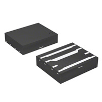
SDP Series - 5x6 QFN
Description This new SIDACtor® Series provides overvoltage protection minimal effect on data signals. This latest silicon design innovation results in capacitive loading characteristic that is compatible with these high bandwidth applications. This surface mount QFN package provides a surge capability that exceeds most worldwide intra-building standards and recommendations for lightning surge withstand capability of secondary protectors. Features and Benefits (30MHz) protection Pinout Designation
Tip in NC Ground Ring in
1 2 3 4 8 7 6 5
Agency Approvals
Agency Agency File Number E133083
surged in excess of ratings
Tip out NC Ground Ring out
Applicable Global Standards
Schematic Symbol Level*
Tip Ground Ring
*Requires series resistance
Electrical Characteristics
VDRM @lDRM=5μA V min SDP0640Q38B SDP0720Q38B SDP0900Q38B SDP1100Q38B SDP1300Q38B SDP1800Q38B SDP2600Q38B SDP3100Q38B SDP3500Q38B SDP06B SDP07B SDP09B SDP10B SDP13B SDP18B SDP26B SDP31B SDP35B 58 65 75 90 120 170 220 275 320 VS @100V/μs V max 77 88 98 130 160 220 300 350 400 IH IS IT A max 2.2 2.2 2.2 2.2 2.2 2.2 2.2 2.2 2.2 VT @IT=2.2 Amps V max 8 8 8 8 8 8 8 8 8
Part Number
Marking
Capacitance
mA min mA max 150 150 150 150 150 150 150 150 150 800 800 800 800 800 800 800 800 800
See Capacitance vs Voltage Graph
Notes: - Absolute maximum ratings measured at TA= 25ºC (unless otherwise noted). - Devices are bi-directional (unless otherwise noted). © 2011 Littelfuse, Inc. Specifications are subject to change without notice. Please refer to www.littelfuse.com for current information. 35 Revised: February 22, 2011
�SIDACtor ® Protection Thyristors
Broadband Optimized™ Protection
V-I Characteristics
+I
Capacitance vs. Voltage
50
IT
Capacitance (pF)
40
IS IH IDRM +V VT VDRM VS
Tip-Ring Tip-GND / Ring-GND
30
-V
20
10
0
0.1
1 Line Voltage (V)
10
100
-I
50/60 Hz Ratings
Parameter Name Test Conditions 0.5s 1s 2s 5s 30s 900s Value 6.5 4.6 3.4 2.3 1.3 0.73 Units
ITSM Maximum non-repetitive on-state current, 50/60 Hz
A
Surge Ratings
IPP Series 2x10μs A min B 250 1.2x50μs/8x20μs A min 230 10x700/5x310μs A min 100 10x1000μs A min 75 ITSM 600VRMS 1 Cycle ARMS 25
Notes: - Peak pulse current rating (IPP) is repetitive and guaranteed for the life of the product. - IPP - The device must initially be in thermal equilibrium with -40°C < TJ <
Thermal Considerations
Package
5 x 6 QFN
Symbol TJ TSTG R0JA
Parameter Junction Temperature Storage Temperature Range Thermal Resistance: Junction to Ambient
Value
Unit °C °C
100
°C/W
© 2011 Littelfuse, Inc. Specifications are subject to change without notice. Please refer to www.littelfuse.com for current information.
36 Revised: February 22, 2011
�SIDACtor ® Protection Thyristors
Broadband Optimized™ Protection
Normalized VS Change vs. Junction Temperature
Normalized DC Holding Current vs. Case Temperature
Percent of VS Change – %
10 8 6 4 2 0 -4 -6 -8 -40 -20 0 20 40 60 80 100 120 140 160
IH (TC = 25ºC)
14 12
2.0 1.8 1.6 1.4 1.2 1.0 0.8 0.6 0.4
-40 -20 0 20 40 60 80 100 120 140 160
IH
25 °C
25°C
Ratio of
Junction Temperature (TJ) – °C
Case Temperature (TC) - ºC
Soldering Parameters
Reflow Condition
- Temperature Min (Ts(min))
Pb-Free assembly (see Fig. 1)
Figure 1
Pre Heat
- Temperature Max (Ts(max)) - Time (Min to Max) (ts)
TP
Ramp-up
tP
Critical Zone TL to TP
60-180 secs.
Temperature
Average ramp up rate (Liquidus Temp (TL) to peak) TS(max) to TL - Ramp-up Rate Reflow
- Temperature (TL) (Liquidus) - Temperature (tL)
TL TS(max)
Preheat
3°C/sec. Max. 3°C/sec. Max. 60-150 secs.
tL
Ramp-down
TS(min)
tS
Peak Temp (TP) Time within 5°C of actual Peak Temp (tp) Ramp-down Rate Time 25°C to Peak Temp (TP) Do not exceed 30 secs. Max. 6°C/sec. Max. 8 min. Max.
25 time to peak temperature (t 25ºC to peak)
Time
Environmental Specifications
High Temp Voltage Blocking 80% Rated VDRM (VAC Peak 504 or 1008 hrs. MIL-STD-750 (Method 1040) JEDEC, JESD22-A-101 cycles. MIL-STD-750 (Method 1051) EIA/JEDEC, JESD22-A104 52 VDC JEDEC, JESD22-A-101 JEDEC, JESD22-A-101 -65°C, 1008 hrs. 10 cycles. MIL-STD-750 (Method 1056) JEDEC, JESD22-A-106
Physical Specifications
Lead Material Terminal Finish Body Material Copper Alloy 100% Matte-Tin Plated UL recognized epoxy meeting flammability classification 94V-0
Temp Cycling Biased Temp & Humidity High Temp Storage Low Temp Storage Thermal Shock Resistance to Solder Heat Moisture Sensitivity Level
© 2011 Littelfuse, Inc. Specifications are subject to change without notice. Please refer to www.littelfuse.com for current information.
37 Revised: February 22, 2011
�SIDACtor ® Protection Thyristors
Broadband Optimized™ Protection
Part Numbering
Part Marking
SDP xxx 0 Q38 B
TYPE SIDACtor DSL Protector MEDIAN VOLTAGE CONSTRUCTION VARIABLE IPP RATING PACKAGE TYPE
XXXXXX Part Marking Code
(Refer to Electrical Characteristics Table)
XXXXX
Date Code
Dimensions — 5x6 QFN
A 5 6 8
Dimension A B
B J E 4 G 3 G1 I I D H K L
Inches Min 0.187 0.226 0.054 0.165 0.027 0.011 0.047 0.097 0.032 0.027 0.100 0.027 0.015 Max 0.207 0.246 0.064 0.171 0.033 0.017 0.053 0.103 0.038 0.033 0.106 0.033 0.021
Millimeters Min 4.745 5.745 1.374 4.199 0.686 0.279 1.194 2.464 0.800 0.686 2.540 0.686 0.381 Max 5.252 6.253 1.628 4.351 0.838 0.432 1.346 2.616 0.953 0.838 2.692 0.838 0.533
C D E F G G1 H I J
PIN 1 INDICATOR
F
C
G1 (REF) G (REF) F (REF)
PIN 1 & 8: TIP CONNECTIONS PIN 3 & 6: GROUND CONNECTIONS PIN 4 & 5: RING CONNECTION
5x6 QFN Solder Pad Layout .0200 .0500
K L
.2920 .2050 .1180
© 2011 Littelfuse, Inc. Specifications are subject to change without notice. Please refer to www.littelfuse.com for current information.
38 Revised: February 22, 2011
�SIDACtor ® Protection Thyristors
Broadband Optimized™ Protection
Packing Options
Package Type Q38
Description 5x6x1.5 QFN Tape and Reel
Quantity 4000
Added Suffix N/A
Industry Standard
EIA-481-D
Tape and Reel Specifications — 5x6 QFN
Reel Dimension
Symbols
C A D B W1 N
Tape Leader and Trailer Dimensions
END
CARRIER TAPE
COVER TAPE
START
A B C D N W1 A0 B0 D0 D1 E1 E2 F
TRAILER 160mm MIN
LEADER 400mm MIN
Tape Dimension Items
K0 P0 P1
D0 T
P0 P2
CARRIER TAPE
D1
E1
P2 T W W0
W0 K0
COVER TAPE
B0 F E2 W P1 A0
Min Max Min Reel Diameter N/A 12.992 N/A Drive Spoke Width 0.059 N/A 1.50 Arbor Hole Diameter 0.504 0.531 12.80 Drive Spoke Diameter 0.795 N/A 20.20 Hub Diameter 1.969 N/A 50.00 Reel Inner Width at Hub 0.488 0.567 12.40 Pocket Width at Bottom 0.204 0.212 5.20 Pocket Length at Bottom 0.244 0.252 6.20 Feed Hole Diameter 0.059 0.063 1.50 Pocket Hole Diameter 0.059 N/A 1.50 Feed Hole Position 1 0.065 0.073 1.65 Feed Hole Position 2 0.400 0.408 10.15 Feed Hole Center 0.212 0.220 5.40 Pocket Hole Center 2 Pocket Depth 0.067 0.075 1.70 Feed Hole Pitch 0.153 0.161 3.90 Component Spacing 0.311 0.319 7 .90 Feed Hole Center 0.077 0.081 1.90 Pocket Hole Center 1 Carrier Tape Thickness 0.010 0.014 0.25 Embossed Carrier 0.460 0.484 11.70 Tape Width Cover Tape Width 0.358 0.366 9.10
Description
Inches
Millimeters Max 330.0 N/A 13.50 N/A N/A 14.40 5.40 6.40 1.60 N/A 1.85 10.35 5.60 1.90 4.10 8.10 2.10 0.35 12.30 9.30
© 2011 Littelfuse, Inc. Specifications are subject to change without notice. Please refer to www.littelfuse.com for current information.
39 Revised: February 22, 2011
�
很抱歉,暂时无法提供与“SDP3500Q38B”相匹配的价格&库存,您可以联系我们找货
免费人工找货