### 物料型号
- 单向型号:SLD10U-017, SLD16U-017, SLD24U-017
- 双向型号:SLD10-018, SLD16-018, SLD24-018
### 器件简介
SLD系列采用高可靠性的行业标准P600轴向引线封装,旨在为敏感电子设备提供精确的过电压保护。
### 引脚分配
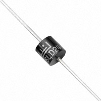
- 色环表示阴极,除了双向型号外。
### 参数特性
- 峰值脉冲功率耗散:2200W(100s x 150ms测试波形)
- 最大瞬时正向电压:3.5V(100A时)
- 工作结温和存储温度范围:-65至175摄氏度
- 典型结到引线热阻:8.0°C
- 典型结到环境热阻:40°C
### 功能详解
- 无卤素、符合RoHS标准
- 玻璃钝化芯片结构,在P600封装中符合ISO 7637-2 4级脉冲5a标准
- 2200W峰值脉冲能力,重复率(占空比):0.01%
- 快速响应时间:从0伏特到最小击穿电压的典型时间少于1.0皮秒
### 应用信息
设计用于保护敏感电子设备免受以下影响:
- 感性负载开关
- 交流发电机负载转储
### 封装信息
- 重量:0.07盎司(2.1克)
- 外壳:P600模塑塑料体,钝化结
- 极性:色环表示阴极,除了双向型号外
- 端头:亚光锡轴向引线,可焊性符合JESD22-B102D标准