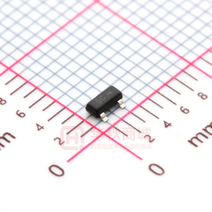
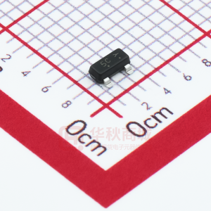
LESHAN RADIO COMPANY, LTD.
Dual Series Schottky Barrier Diodes
These Schottky barrier diodes are designed for high speed switching applications, circuit protection, and voltage clamping. Extremely low forward voltage reduces conduction loss. Miniature surface mount package is excellent for hand held and portable applications where space is limited. • Extremely Fast Switching Speed • Low Forward Voltage — 0.35 Volts (Typ) @ I F = 10 mAdc
ANODE 1 3
LBAT54CLT1
3
1 2
SOT-23
ANODE 2
ORDERING INFORMATION
Device LBAT54CLT1 Package SOT–23 Shipping 3000/Tape & Reel
CATHODE
Preferred: devices are recommended choices for future use and best overall value.
DEVICE MARKING
LBAT54CLT1 = KL3
MAXIMUM RATINGS (T J = 125°C unless otherwise noted)
Rating Reverse Voltage Forward Power Dissipation @ T A = 25°C Derate above 25°C Forward Current(DC) Junction Temperature Storage Temperature Range Symbol VR PF Value 30 225 1.8 200Max 125Max –55 to +150 Unit Volts mW mW/°C mA °C °C
IF TJ T stg
ELECTRICAL CHARACTERISTICS (T A = 25°C unless otherwise noted)
Characteristic Reverse Breakdown Voltage (I R = 10 µA) Total Capacitance (V R = 1.0 V, f = 1.0 MHz) Reverse Leakage (V R = 25 V) Forward Voltage (I F = 0.1 mAdc) Forward Voltage (I F = 30 mAdc) Forward Voltage (I F = 100 mAdc) Reverse Recovery Time (I F = I R = 10 mAdc, I R(REC) = 1.0 mAdc, Figure 1) Forward Voltage (I F = 1.0 mAdc) Forward Voltage (I F = 10 mAdc) Forward Current (DC) Repetitive Peak Forward Current Non–Repetitive Peak Forward Current (t < 1.0 s) Symbol V(BR)R CT IR VF VF VF trr VF VF IF IFRM IFSM Min 30 — — — — — — — — — — — Typ — 7.6 0.5 0.22 0.41 0.52 — 0.29 0.35 — — — Max — 10 2.0 0.24 0.5 0.8 5.0 0.32 0.40 200 300 600 Unit Volts pF µAdc Vdc Vdc Vdc ns Vdc Vdc mAdc mAdc mAdc
LBAT54CLT1–1/2
LESHAN RADIO COMPANY, LTD.
LBAT54CLT1
820 Ω +10 V 2k 100 µH 0.1 µF DUT 50 Ω OUTPUT PULSE GENERATOR 50 Ω INPUT SAMPLING OSCILLOSCOPE 90% VR INPUT SIGNAL IR iR(REC) = 1 mA OUTPUT PULSE (IF = IR = 10 mA; measured at iR(REC) = 1 mA) IF 0.1 µF tr 10% tp t IF trr t
Notes: 1. A 2.0 kΩ variable resistor adjusted for a Forward Current (IF) of 10 mA. Notes: 2. Input pulse is adjusted so IR(peak) is equal to 10 mA. Notes: 3. tp » trr
Figure 1. Recovery Time Equivalent Test Circuit
100 IR , REVERSE CURRENT (µA) IF, FORWARD CURRENT (mA) 1000 100 TA = 125°C 10 1.0 TA = 85°C 0.1 0.01 TA = 25°C 0.001 0.1 0.2 0.3 0.4 0.5 0.6 0 5 VF, FORWARD VOLTAGE (VOLTS) 10 15 20 VR, REVERSE VOLTAGE (VOLTS) 25 30 TA = 150°C
10
1 50°C
1 25°C 1.0 85°C 25°C – 40°C
– 55°C
0.1 0.0
Figure 2. Forward Voltage
Figure 3. Leakage Current
14 C T , TOTAL CAPACITANCE (pF) 12 10 8 6 4 2 0 0 5 10 15 20 25 30
VR, REVERSE VOLTAGE (VOLTS)
Figure 4. Total Capacitance
LBAT54CLT1–2/3
LESHAN RADIO COMPANY, LTD.
LBAT54CLT1
SOT-23
NOTES:
A L
3 1 2
1. DIMENSIONING AND TOLERANCING PER ANSI Y14.5M, 1982. 2. CONTROLLING DIMENSION: INCH.
BS
DIM A B C D G H J K L S V
V
G
C D H K J
INCHES MIN MAX 0.1102 0.1197 0.0472 0.0551 0.0350 0.0440 0.0150 0.0200 0.0701 0.0807 0.0005 0.0040 0.0034 0.0070 0.0140 0.0285 0.0350 0.0401 0.0830 0.1039 0.0177 0.0236
MILLIMETERS MIN MAX 2.80 3.04 1.20 1.40 0.89 1.11 0.37 0.50 1.78 2.04 0.013 0.100 0.085 0.177 0.35 0.69 0.89 1.02 2.10 2.64 0.45 0.60
PIN 1. ANODE 2. ANODE 3. CATHODE
0.037 0.95
0.037 0.95
0.079 2.0 0.035 0.9 0.031 0.8
inches mm
LBAT54C-3/3
很抱歉,暂时无法提供与“LBAT54CLT1”相匹配的价格&库存,您可以联系我们找货
免费人工找货- 国内价格
- 20+0.06724
- 200+0.06324
- 500+0.05923
- 1000+0.05523
- 3000+0.05323
- 6000+0.05043