LESHAN RADIO COMPANY, LTD.
Schottky Barrier Diodes
Designed primarily for UHF mixer applications but suitable also for use in detector and ultra-fast switching circuits.Supplied in an inexpensive plastic package for low-cost,high-volume consumer requirements.Also available in Surface Mount package.
MMBD101LT1
SILICON SCHOTTKY BARRIER DIODES
• Low Noise Figure—6.0dB Typ@1.0GHz • Very Low Capacitance—Less Than 1.0pF@zero Volts • High Forward Conductance—0.5volts(typ)@IF=10mA
3
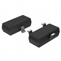
3 CATHODE
1 ANODE
1 2
CASE 318–08, STYLE 6 SOT– 23 (TO–236AB)
MAXIMUM RATINGS
MBD101 MMBD101LT1 Rating symbol value unit Reverse Voltage vR 7.0 Volts Forward Power Dissipation pF @TA=25 °C 280 225 mW Derate above 25 °C 2.2 1.8 mW/ °C Junction Temperature TJ +150 °C Storage Temperature Range Tstg –55 to +150 °C DEVICE MARKING MMBD101LT1=4M ELECTRICAL CHARACTERISTICS(TA=25 °C unless otherwise noted) Characteristic Symbol Min Typ Reverse Breakdown Voltage V(BR)R 7.0 10 (IR= 10µAdc) Diode Capacitance (VR= 0,f =1.0MHz,Note1) Forward Voltage(1) (I F= 10mAdc) Reverse Leakage (VR= 3.0Vdc) NOTE: MMBD101LT1 is also available in bulk packaging.Use MMBD101L as the device title to order this device in bulk. CT VF IR — — — 0.88 0.5 0.02 1.0 0.6 0.25 pF Volts
Max —
Unit Volts
µ Adc
G15–1/2
�LESHAN RADIO COMPANY, LTD.
MMBD101LT1
TYPICAL CHARACTERISTICS
(T A = 25°C unless noted)
1.0
100
I R, REVERSE LEAKAGE ( µA)
I F , FORWARD CURRENT (mA)
0.7 0.5
V R= 3.0Vdc
0.2 0.1 0.07 0.05
T A = 85°C
10
T A = –40°C
10
T A = 25°C
0.02 0.01 30 40 50 60 70 80 90 100 110 120 130
0.1 0.3 0.4 0.5 0.6 0.7
T A , AMBIENT TEMPERATURE (°C)
V F , FORWARD VOLTAGE (VOLTS)
Figure 1. Reverse Leakage
1.0 1 1 10
Figure 2. Forward Voltage
LOCAL OSCILLATOR FREQUENCY = 1.0 GHz (TEST CIRCUIT IN FIGURE 5)
C, CAPACITANCE (pF)
0.9
NF, NOISE FIGURE (dB)
0 1.0 2.0 3.0 4.0
9.0 8.0 7.0 6.0 5.0 4.0 3.0 2.0 1.0 0.1 0.2
0.8
0.7
0.6
0.5
1.0
2.0
5.0
10
V R , REVERSE VOLTAGE (VOLTS)
P LO , LOCAL OSCILLATOR POWER (mW)
Figure 3. Capacitance
Figure 4. Noise Figure
LOCAL OSCILLATOR
NOTES ON TESTING AND SPECIFICATIONS
Note 1 — C C and C T are measured using a capacitance bridge
UHF NOISE SOURCE H.P. 349A
DIODE IN TUNED MOUNT
(Boonton Electronics Model 75A or equivalent). Note 2 — Noise figure measured with diode under test in tuned diode mount using UHF noise source and local oscillator (LO) frequency of 1.0 GHz. The LO power is adjusted for 1.0 mW. IF amplifier NF = 1.5 dB, f = 30 MHz, see Figure 5. Note 3 — L S is measured on a package having a short instead of a die, using an impedance bridge (Boonton Radio Model 250A RX Meter).
NOISE FIGURE METER H.P. 342A
IF AMPLIFIER NF = 1.5 dB f = 30 MHz
Figure 5. Noise Figure Test Circuit
G15–2/2
�
很抱歉,暂时无法提供与“MMBD101LT1”相匹配的价格&库存,您可以联系我们找货
免费人工找货