0
登录后你可以
  • 下载海量资料
  • 学习在线课程
  • 观看技术视频
  • 写文章/发帖/加入社区
会员中心
创作中心
发布
  • 发文章

  • 发资料

  • 发帖

  • 提问

  • 发视频

创作活动
3VV1

3VV1

  • 厂商:

    MACOM

  • 封装:

  • 描述:

    3VV1 - Multipurpose Power Line RFI Filter for Emission Control - Tyco Electronics

  • 详情介绍
  • 数据手册
  • 价格&库存
3VV1 数据手册
Corcom Product Guide Catalog: 1654001 Issue Date: 06.2011 Multipurpose Power Line RFI Filter for Emission Control V and W Series UL Recognized CSA Certified VDE Approved VV1 / VW1 VV6 / VW6 Both the V and W series are effective to control emissions in equipment using SCR and T2L circuits for compliance with FCC Part 15, Subpart J and EN55022, Level A, down to 150kHz Specifications Maximum leakage current each Line to Ground: @ 120 VAC 60 Hz: .5 mA @250 VAC 50 Hz: .82 mA Hipot rating (one minute): Line to Ground: Line to Line: Rated Voltage (max): Operating Frequency: Rated Current: 2250 VDC 1450 VDC 250 VAC 50/60 Hz 3 to 20A* V S er i es • Offers an N = 3 (“T”) Line to Ground impedance to common mode and an N = 5 “Dbl. Pi”) impedance for Line to Line differential mode interference • Designed for susceptibility use when equipment impedance at RF frequencies is low W Series • Offers an N = 4 (“Dbl. L”) Line to Ground impedance for common mode and an N=5 (“Dbl. Pi”) impedance for Line to Line differential mode interference • Designed for use when equipment impedance at RF frequencies is high • Two stage construction provides excellent suppression at high frequencies Operating Ambient Temperature Range (at rated current Ir): -10°C to +40°C In an ambient temperature (Ta) higher than +40°C the maximum operating current (Io) is calculated as follows: Io = Ir (85-Ta)/45 Electrical Schematics V Series LINE LOAD Ordering Information 20 V V 6 Input / Output Style 1 – .250 [6.3] spade terminals 6 – Threaded bolt 7 – IEC inlet* (line side) .250 [6.3] spade terminals (load side) W Series (3, 6 & 10A) LINE LOAD W Series (20A) LINE LOAD V or W Series Leakage current designation V – Standard Current Rating 3, 6, 10 or 20A *IEC 60320-1 C20 inlet mates with C19 connector 20VW7, 20A model tested by Underwriters Laboratories to US and Canadian requirements and is VDE approved at 16A, 250VAC For email, phone or live chat, please go to te.com/help corcom.com 86 Dimensions are in inches and millimeters unless otherwise specified. Values in italics are metric equivalents. Dimensions are shown for reference purposes only. Specifications subject to change. Corcom Product Guide Catalog: 1654001 Issue Date: 06.2011 Multipurpose Power Line RFI Filter for Emission Control (continued) V and W Series Available Part Numbers 3VV1 6VV1 10VV1 20VV1 20VV6 3VW1 3VW1 10VW1 20VW1 20VW6 20VW7* Case Styles (continued) VW7 Threaded inserts 2.25 57.15 B 1 RFI Power Line Filters .047 ± .010 1.19 ± .25 5.33 ± .025 135.38 ± .635 Case Styles V1 / W1 (3, 6 & 10A)      A C     B Recommended Panel Cutout .157 3.98 Dia. 2.30 58.42 D E A     C    1.22 30.99 C L .75 19.05 1.60 40.46 .219 R 5.56 Mounting Plane 2.12 53.85 V1 / W1 (20A) Case Dimensions Part No. A  B  C  EDB 3VV1, 3VW1 2.00 50.8     A C    V6 / W6 EDB       6VV1, 6VW1     10VV1, 10VW1     20VV1, 20VW1     20VV6, 20VW6     20VW7                            D E             2.00 50.8    A C *20VW7, 20A model tested by Underwriters Laboratories to US and Canadian requirements and is VDE approved at 16A, 250VAC    87 Dimensions are in inches and millimeters unless otherwise specified. Values in italics are metric equivalents. Dimensions are shown for reference purposes only. Specifications subject to change. For email, phone or live chat, please go to te.com/help corcom.com Corcom Product Guide Catalog: 1654001 Issue Date: 06.2011 Multipurpose Power Line RFI Filter for Emission Control (continued) V and W Series Performance Data Typical Insertion Loss Measured in closed 50 Ohm system Common Mode / Asymmetrical (L-G) Differential Mode / Symmetrical (L-L) 3VV db 100 90 80 70 60 50 40 30 20 10 0 0.1 1 10 30 Frequency in MHz 6VV db 100 90 80 70 60 50 40 30 20 10 0 0.1 1 10 30 Frequency in MHz 10VV db 100 90 80 70 60 50 40 30 20 10 0 0.1 1 10 30 Frequency in MHz 20VV db 100 90 80 70 60 50 40 30 20 10 0 0.1 1 10 30 Frequency in MHz 3VW db 100 90 80 70 60 50 40 30 20 10 0 0.1 1 10 30 Frequency in MHz 6VW db 100 90 80 70 60 50 40 30 20 10 0 0.1 1 10 30 Frequency in MHz 10VW db 100 90 80 70 60 50 40 30 20 10 0 0.1 1 10 30 Frequency in MHz 20VW db 100 90 80 70 60 50 40 30 20 10 0 0.1 1 10 30 Frequency in MHz Minimum Insertion Loss Measured in closed 50 Ohm system Common Mode / Asymmetrical (Line to Ground)             88 Dimensions are in inches and millimeters unless otherwise specified. Values in italics are metric equivalents. Dimensions are shown for reference purposes only. Specifications subject to change. For email, phone or live chat, please go to te.com/help corcom.com Differential Mode / Symmetrical (Line to Line)                                                                                                                                                              
3VV1
1. 物料型号: - V系列和W系列的型号包括3VV1、3VW1、6VV1、6VW1、10VV1、10VW1、20VV1、20VW1、20VV6、20VW6和20VW7。

2. 器件简介: - V系列提供共模(Line to Ground)N=3("T")阻抗和差模(Line to Line)N=5("Dbl. Pi")阻抗。 - W系列提供共模N=4("Dbl.L")阻抗和差模N=5("Dbl. Pi")阻抗。 - V系列适用于设备在RF频率下阻抗较低时的敏感性使用,而W系列适用于设备在RF频率下阻抗较高时使用,且具有两级结构,在高频下提供出色的抑制效果。
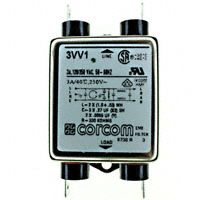
3. 引脚分配: - 输入/输出样式1为.250 [6.3] spade terminals(线侧),.250 [6.3] spade terminals(负载侧)。

4. 参数特性: - 最大漏电流:每条线对地.5 mA。 - 耐压等级(一分钟):线对地2250 VDC,线对线1450VDC。 - 额定电压(最大):250 VAC。 - 操作频率:50/60 Hz。 - 额定电流:3到20A。

5. 功能详解: - V和W系列均有效控制使用SCR和T2L电路的设备中的辐射,以符合FCC第15部分J和EN55022、A级、低至150kHz的标准。

6. 应用信息: - 适用于需要控制辐射的应用,如电子设备。

7. 封装信息: - 提供了不同型号的封装尺寸,包括V1/W1(3, 6 & 10A)、V1/W1(20A)、V6/W6等,具体尺寸以英寸和毫米为单位提供。

很抱歉,暂时无法提供与“3VV1”相匹配的价格&库存,您可以联系我们找货

免费人工找货