Catalog 1308242 Issued 3-03
P&B
CNT series
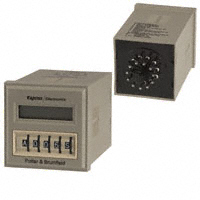
Multifunction, Digital Time Delay Relay/Counter
• • • • • • • 10 programmable timing modes + 2 counting modes 0.1 sec. to 9,990 hr. programmable timing range 1 to 99,900 counting range LCD digital display Universal (24-240VAC/VDC) and fixed input types 10A output relay with DPDT contacts Thumbwheel switches for programming
File E22575 File LR15734
Users should thoroughly review the technical data before selecting a product part number. It is recommended that user also seek out the pertinent approvals files of the agencies/laboratories and review them to ensure the product meets the requirements for a given application.
Timing and Counting Modes
See the following page for a complete description of all programmable timing and counting modes.
Input Data @ 25°C
Voltage: Universal Input Type: 24 - 240V ± 15%, 50/60 Hz. AC or DC. Fixed Input Types: 120VAC ± 15%, 50/60 Hz and 12VDC. Power Requirement: Universal Input Type: 10VA @ 240VAC; 5VA @ 120VAC; 1VA @ 24VAC. 10W @ 240VDC; 5W @ 120VDC; 1W @ 24VDC. Fixed Input Types: 3VA @ 120VAC; 3W @ 12VDC. Transient Protection: Yes. Reverse Voltage Protection: Yes.
Timing Specifications
Timing Ranges: 0.1 to 99.9 / 1 to 999 sec.; 0.1 to 99.9 / 1 to 999 min.; 0.1 to 99.9 / 1 to 999 / 10 to 9,990 hr. Timing Adjustment: Digital adjustment via thumbwheel switches. Tolerance: ± 0.5% ± 0.05 sec. Delta Time (for AC units add ±1 cycle 60 Hz.): ± 0.1% ± 0.05 sec. Repeatability (Including first cycle of operation.): ± 0.1% ± 0.05 sec. Reset Time (power interruption): 45 ms, typ.; 60 ms, max. Minimum Pulse Width, Control: 50 ms. Recycle Time: 45 ms, typ.; 60 ms, max.
Input Voltages & Limits @ 25°C
Input Type Universal Fixed Nominal Voltage 24-240VAC/VDC 120VAC 12VDC Minimum Voltage 20.4VAC/VDC 102VAC 10.2VDC Maximum Voltage 276VAC/VDC 138VAC 13.8VDC
Counting Specifications
Maximum Count: 1 to 999; 10 to 9,990 (÷10); 100 to 99,900 (÷100). Maximum Count Rate: 100 counts per second. Mimumum Pulse Width:Count (Control): 3 ms.; Reset: 3 ms. Available Counting Functions: Operate at preset count and release at preset count.
Note: DC voltage must be filtered (5% p-p ripple max. at nom. voltage). AC models will operate on 50 or 60 Hz.
Environmental Data
Temperature Range: Storage: -20°C to +70°C. Operating: -10°C to +55°C. Humidity: 85% relative humidity, non-condensing.
Contact Data @ 25°C
Arrangements: 2 Form C (DPDT). Material: Silver-cadmium oxide alloy. Rating: 10A @ 30VDC or 277VAC, resistive; 1/2 HP @ 250VAC; 1/3 HP @ 120VAC. Expected Mechanical Life: 10 million operations. Expected Electrical Life: 100,000 operations, min., at rated load.
Mechanical Data
Termination: 11-pin octal style plug. Enclosure: Beige plastic 1/16 DIN case. Sockets: Fits either 27E123 or 27E892 (snap-on) screw terminal sockets. Weight: 4.3 oz. (122g) approximately. External Control: CONTROL, RESET: Active on contact closure or solid state switch closure to RETURN, 0-1.0VDC maximum voltage level (see wiring diagrams for interface circuits.
Initial Dielectric Strength
Between Open Contacts: 1,000V rms, 60 Hz. Between All Other Conductors: 1,500V rms, 60Hz.
Ordering Information – Authorized distributors are more likely to stock boldface items listed below.
Universal Input Model
Input Voltage 24-240VAC/VDC Part Number CNT-35-96
Accessories
Part Number SSA-24C667 Name Mounting Clip Description Ratchet-fit clip slides onto CNT from behind to secure CNT in panel mount applications. SSA-24C668 Protective Cover Clear, flexible cover slips snugly over bezel of CNT to help protect against dust and moisture. Durable cover also helps prevent inadvertant changes of programming switch settings.
Fixed Input Models
Input Voltage 12VDC 120VAC Part Number CNT-35-26 CNT-35-76
Outline Dimensions
1.88 (47 .8) .32 (8.1)
O
NC N
Wiring Diagrams (Bottom Views)
2.83 (71.9)
(pins numbered clockwise from keyway)
EXTERNAL CONTROL SWITCHES** CONTROL (COUNT) RETURN
1.76 (44.7)
RESET CONTROL RETURN USE SAME FOR RESET
RESET
1.88 (47 .8)
A 1 1 1 H
+
.64 (16.3)
1 11 INPUT* _
+
1 11 INPUT*
_
Fits 1.77 x 1.77 (45 x 45) Panel cutout
3.15 (80.0)
* Note: Input polarity for DC operation. For most reliable operation on AC, connect high side to “+” and low side to “–”. ** Important: A dry circuit switch is recommended. A “dry circuit” switch is one rated to reliably switch currents of less than 50mA. Use of a switch rated for other than dry circuit may result in failure of the time delay relay to function properly.
Dimensions are shown for reference purposes only.
Dimensions are in inches over (millimeters) unless otherwise specified.
Specifications and availability subject to change.
www.tycoelectronics.com Technical support: 1211 Refer to inside back cover.
�Catalog 1308242 Issued 3-03
P&B
Protective Cover & Mounting Clip Dimensions
SSA-24C668
Protective Cover
“A ” 1.99 (50.5) .40 (10.2)
SSA-24C667
Mounting Clip
2.283 1.970 (58.0) (50.0)
1.99 (50.5)
2.047 (52.0) .591 (15.0)
“A ”
Section "A-A"
1.654 (42.0) 1.890 (48.0)
Programming Switch Diagram
With this setting, the relay would operate after a delay period of 214 seconds. Function Select: Timer Mode: A = Delay On Operate B = Delay On Release C = Interval On D = Control-Off Interval On B = Divide by 10 E = Recycle F = Single Cycle G = Control On-Off Interval On H = Control On-Off Delay C = Divide by 100 I = Pulse J = Cumulative Delay On Operate
A
2
1
4
S
Counter Mode:
A & D-J = Normal Count
Time/Counter Setting: 001 to 999 Time Base/Counter Mode Select: Time Base: .1S = 0.1 to 99.9 Sec. .1M = 0.1 to 99.9 Min. .1H = 0.1 to 99.9 Hrs. S = 1 to 999 Sec. M = 1 to 999 Min. H = 1 to 999 Hrs. Counter Mode: CO = Operate at Preset Count CR = Release at Preset Count 10H =10 to 9990 Hrs.
Timer Function Descriptions
A . Delay On Operate
Output relay turned on at end of programmed time interval which is started by CONTROL input or power-on with CONTROL on. Relay turned off by RESET input until next cycle is started. With CONTROL on, turning RESET off restarts timing
B. Delay On Release
Output relay turned on with CONTROL input and remains on for programmed time interval following removal of CONTROL. During time interval after release of CONTROL, RESET turns relay off until cycle restarted with reapplication of CONTROL. With CONTROL on, relay is held off while RESET is activated.
C. Interval On
Output relay turned on for programmed time interval by CONTROL or poweron with CONTROL on. RESET turns relay off until next cycle is started, and does not restart timing when RESET is removed.
D. Control-Off Interval On
Output relay turned on for programmed time interval by turn-off of CONTROL. RESET turns relay off until next cycle is started, and does not restart timing when RESET is removed.
E. Recycle
Output relay turned on at end of programmed time interval which is started by momentary CONTROL input or power-on with CONTROL on. Relay stays on for equal time interval, then turns off and cycle is repeated on a freerunning basis until terminated by momentary RESET, turning relay off. With CONTROL on, turning RESET off restarts cycle.
F. Single Cycle Output relay turned on at end of programmed time interval which is
started by momentary CONTROL input or power-on with CONTROL on. Relay stays on for equal time interval, then turns off. RESET terminates timing and turns relay off. Turning RESET off does not restart timing. G. Control On-Off Interval On (Watch Dog Timer) Output relay turned on and programmed time interval started or restarted by change of CONTROL input. RESET turns relay off and stops timing. Turning RESET off does not restart timing. H. Control On-Off Delay Output relay turned on at end of programmed timing interval which is started or restarted by change of CONTROL input. If relay is on, turn-off of relay occurs at end of programmed time interval which is started or restarted by change of CONTROL input. RESET turns relay off and stops timing. Turning RESET off does not restart timing. I. Pulse Output relay turned on at end of programmed time interval, which is started by CONTROL input, for 0.5 second duration, and continues in pulsed mode at programmed time interval with fixed 0.5 second on-time. Turning CONTROL off turns relay off and stops timing. RESET turns relay off and inhibits operation. With CONTROL on, removal of RESET restarts timing. J. Cumulative Delay On Operate Output relay turned on at completion of total accumulate CONTROL input duration equal to programmed time. Turning CONTROL off before accumulation of programmed time results in measured time total being held until CONTROL is again turned on and total programmed time value is reached. RESET input resets time value to zero and turns relay off if energized. Turning RESET off restarts timing if CONTROL is on.
Counter Function Descriptions
CO – Operate at Preset Count – Normal Mode
After initializing by momentary activation of RESET input, each on/off signal at COUNT (CONTROL) input increments displayed count in upcounting manner from initial 000 value until preset count, set by thumbwheel switches, is reached and output relay turns on. Additional inputs continue to increment displayed count. Continued counting past maximum count (999) results in a “wrap-around” effect to 000, followed by contrinued up-counting. Activation of RESET input turns relay off and resets count to zero.
CR – Release at Preset Count – Normal Mode
Initializing by momentary activation of RESET input turns relay on. Operation is similar to CO (Operate at Preset Count) except relay turns off at a preset count.
CO or CR – Divide-by-10 Mode
Operation is as described previously, except count is incremented for every 10 on/off input signals for a maximum presettable count of 9,990.
CO or CR – Divide-by-100 Mode
Operation is as described previously, except count is incremented for every 100 on/off input signals for a maximum presettable count of 99,900.
Dimensions are shown for
1212 reference purposes only.
Dimensions are in inches over (millimeters) unless otherwise specified.
Specifications and availability subject to change.
www.tycoelectronics.com Technical support: Refer to inside back cover.
�