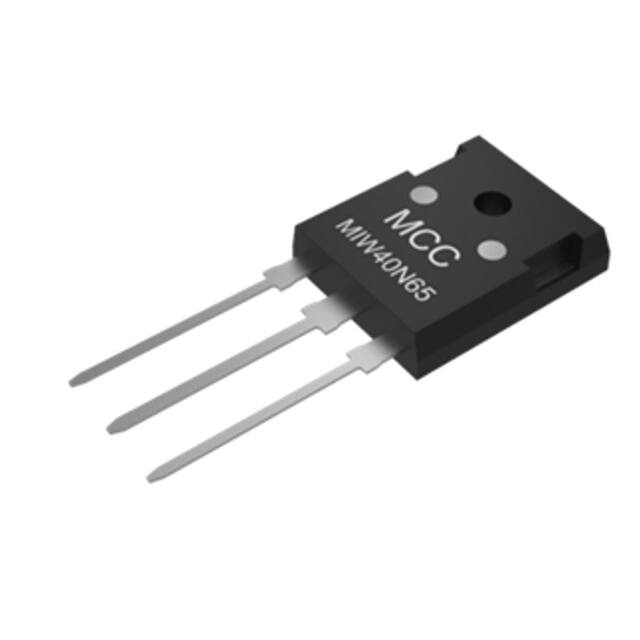
MIW40N65
Features
•
•
Low Vce(sat),Fast Switching
Vce(sat) with Positive Temperature Coefficient
•
•
•
•
•
High Ruggedness, Good Thermal Stability
Very Tight Parameter Distribution
Halogen Free
Epoxy Meets UL 94 V-0 Flammability Rating
Lead Free Finish/RoHS Compliant ("P" Suffix Designates RoHS
Compliant. See Ordering Information)
Trench and
Field Stop
IGBT
650V 40A
Maximum Ratings
•
Operating Junction Temperature Range : -55°C to +150°C
•
Storage Temperature Range: -55°C to +150°C
•
IGBT Thermal Resistance: 0.45°C/W Junction to Case
•
Diode Thermal Resistance: 1.25°C/W Junction to Case
•
Thermal Resistance: 40°C/W Junction to Ambient
Parameter
Collector‐Emitter Voltage
DC Collector Current(1)
TC=25℃
Diode Forward Current (1)
TC=25℃
Unit
VCE
650
V
IC,pluse
IF
TC=100℃
Diode Pulsed Current (2)
Gate‐Emitter Voltage
Short Circuit Withstand Time (3)
VGE=15V, VCC=400V, TJ≤150°C
Power Dissipation
Rating
IC
TC=25℃
TC=100℃
C
E
B
Symbol
TC=100℃
Pulsed Collector Current (2)
TO-247
A
Q
80
A
120
2
1
40
3
P
A
F
40
A
IF,pluse
120
A
VGE
±20
V
K
V
20
J
D
G
tSC
PD
10
μs
280
W
110
Note:
1. Limited by TJmax.
2. Tp limited by TJmax.
3. Allowed number of short circuits: 1s.
Internal Structure
2(C)
DIM
A
B
C
D
E
F
J
K
P
Q
V
G
DIMENSIONS
INCHES
MM
MIN MAX MIN MAX
0.787 0.866 20.00 22.00
0.598 0.638 15.20 16.20
0.185 0.208 4.70 5.30
0.035 0.059 0.90 1.50
0.059 0.094 1.50 2.40
0.067 0.091 1.70 2.30
0.019 0.031 0.48 0.80
0.748 0.833 19.00 21.15
0.122 0.189 3.10 4.80
0.118 0.150 3.00 3.80
0.106 0.134 2.70 3.40
0.197 0.224 5.00 5.70
NOTE
Φ
1(G)
3(E)
Rev.3-1-05072020
1/5
MCCSEMI.COM
�MIW40N65
Electrical Characteristics @ 25°C (Unless Otherwise Specified)
Parameter
Symbol
Test Conditions
Min
Typ
Max
Unit
Static Characteristics
Collector‐Emitter
Breakdown Voltage
V(BR)CES
Collector‐Emitter
Saturation Voltage
VCE(sat)
Diode Forward Voltage
G‐E Threshold Voltage
C‐E Leakage Current
VF
VGE(th)
ICES
VGE=0V, IC=0.25mA
650
V
VGE=15V, IC=40A
1.9
VGE=15V, IC=40A, TJ=150℃
2.4
VGE=0V, IF=20A
1.8
VGE=0V, IF=20A, TJ=150℃
1.6
IC=1mA, VCE=VGE
V
V
4
5.7
VCE=650V, VGE=0V
IGES
VCE=0V, VGE=20V
Transconductance
gFS
VCE=20V, IC=40A
7
V
0.1
mA
4
VCE=650V, VGE=0V, TJ=150℃
G‐E Leakage Current
2.4
250
24
nA
S
Dynamic Characteristics
Input Capacitance
Cies
Output Capacitance
Coes
Reverse Transfer Capacitance
Cres
Gate Charge
Qg
3155
VCE=30V,VGE=0V,f=1MHz
175
pF
81.5
VCC=400V,IC=40A,VGE=15V
165
nC
IGBT Switching Characteristics
Turn-On Delay Time
Rise Time
Turn-Off Delay Time
Fall Time
td(on)
62
tr
54
td(off)
265
tf
ns
VCC=600V, IC=40A,
VGE=0/15V, RG=10Ω,
Inductive load
30
Turn‐On Energy
Eon
Turn‐Off Energy
Eoff
1.4
Total Switching Energy
Ets
4.7
Reverse Recovery Time
trr
41
ns
Reverse Recovery Charge
Qrr
0.31
μC
Peak Reverse Recovery Current
Irrm
13.3
A
3.3
mJ
Diode Characteristics
Rev.3-1-05072020
VR=400V, IF=20A,
diF/dt=200A/μs
2/5
MCCSEMI.COM
�MIW40N65
Curve Characteristics
Fig. 1 - FBSOA
Fig. 2 - RBSOA
1μs
100
10
Collector Current (A)
Collector Current (A)
100
50μs
100μs
1
1ms
TJ(max)=150°C
TC=25°C
Single Pulse
0.1
10
DC
1
1
10
100
1000
1
10
Collector-Emitter Voltage(V)
Fig. 3 - Typical Output Characteristics
200
17V
19V
1000
Fig. 4 - Typical Output Characteristics
200
TJ=25°C
100
Collector-Emitter Voltage(V)
19V
TJ=125°C
15V
17V
13V
120
11V
80
40
0
15V
160
Collector Current (A)
Collector Current (A)
160
VGE=9V
0
1
2
3
4
5
6
7
13V
120
11V
80
VGE=9V
40
0
8
0
1
2
Collector-Emitter Voltage(V)
5
6
7
8
4
Collector-Emitter Saturation Voltage(V)
Collector Current (A)
4
Fig. 6 - VCE(sat) —TC
Fig. 5 - VCE(sat) —IC
80
60
40
TJ=25°C
TJ=125°C
20
0
3
Collector-Emitter Voltage(V)
0
1
2
3
4
Collector-Emitter Saturation Voltage(V)
Rev.3-1-05072020
3/5
IC=80A
3
IC=40A
2
IC=20A
1
0
25
50
75
100
125
TC (°C)
MCCSEMI.COM
�MIW40N65
Curve Characteristics
Fig. 8 - VCE—VGE
Fig. 7 - VCE—VGE
16
16
TC=125°C
Collector-Emitter Voltage(V)
Collector-Emitter Voltage(V)
TC=25°C
12
IC=40A
8
4
IC=80A
12
IC=40A
8
IC=80A
4
IC=20A
IC=20A
0
0
4
8
16
12
0
20
0
4
IC=40A
Gate-Emitter Voltage (V)
Cies
3500
Capacitance (pF)
20
15
4000
3000
2500
2000
1500
1000
Cres
0
5
12
VCE=100V
VCE=480V
9
6
3
Coes
500
10
15
20
25
30
35
0
40
0
30
60
Collector-Emitter Voltage (V)
Fig. 11 - Power Derating Curve
150
180
Fig. 12 - Collector Current Derating Curve
Collector Current (A)
80
200
150
100
60
40
20
50
50
75
100
125
150
Case Temperature (°C)
Rev.3-1-05072020
120
100
250
0
25
90
Gate Charge(nC)
300
Power Dissipation (W)
16
12
Fig. 10 - Gate Charge
Fig. 9 - Capacitance Characteristics
4500
0
8
Gate-Emitter Voltage(V)
Gate-Emitter Voltage(V)
0
25
50
75
100
125
150
Case Temperature (°C)
4/5
MCCSEMI.COM
�MIW40N65
Ordering Information
Device
Packing
Part Number-BP
Tube:30pcs/Tube, 360pcs/Box,1.8K/Ctn;
Note : Adding "-HF" Suffix For Halogen Free, eg. Part Number-BP-HF
***IMPORTANT NOTICE***
Micro Commercial Components Corp. reserves the right to make changes without further notice to any product herein to
make corrections, modifications , enhancements , improvements , or other changes . Micro Commercial Components
Corp . does not assume any liability arising out of the application or use of any product described herein; neither does it
convey any license under its patent rights ,nor the rights of others . The user of products in such applications shall assume all
risks of such use and will agree to hold Micro Commercial Components Corp . and all the companies whose products are
represented on our website, harmless against all damages. Micro Commercial Components Corp. products are sold subject
to the general terms and conditions of commercial sale, as published at
https://www.mccsemi.com/Home/TermsAndConditions.
***LIFE SUPPORT***
MCC's products are not authorized for use as critical components in life support devices or systems without the express
written approval of Micro Commercial Components Corporation.
***CUSTOMER AWARENESS***
Counterfeiting of semiconductor parts is a growing problem in the industry. Micro Commercial Components (MCC) is taking
strong measures to protect ourselves and our customers from the proliferation of counterfeit parts. MCC strongly encourages
customers to purchase MCC parts either directly from MCC or from Authorized MCC Distributors who are listed by country on
our web page cited below. Products customers buy either from MCC directly or from Authorized MCC Distributors are genuine
parts, have full traceability, meet MCC's quality standards for handling and storage. MCC will not provide any warranty
coverage or other assistance for parts bought from Unauthorized Sources. MCC is committed to combat this global
problem and encourage our customers to do their part in stopping this practice by buying direct or from authorized
distributors.
Rev.3-1-05072020
5/5
MCCSEMI.COM
�
很抱歉,暂时无法提供与“MIW40N65-BP”相匹配的价格&库存,您可以联系我们找货
免费人工找货