EVB90121
MLX90121 Evaluation Board
Features and Benefits
Output power up to 200miliwatts
Complies with standard ISO15693 and ISO 14443 protocols
Programmable encoder for custom protocol
Short to medium reading range applications
Matching network optimized for 50 ohm antenna impedance
10 pins connector for communication with a microcontroller
Board voltage supplied by a jack connector from 6 to 9 Volts DC
Internal power supply of the board between 3 Volts and 5 Volts DC
Ordering Information
Part No.
EVB90121
Applications Examples
Evaluation Board EVB90121
Freight identification systems
Smart labels and write systems
Access control systems
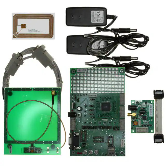
General Description
The EVB90121 is an assembled module that allows to evaluate the advantages of the MLX90121 13MHz
transceiver IC and to facilitate the development of RFID applications.
The board voltage is supplied by a jack connector from 6 to 9 Volts DC. The internal power supply of the
board can be chosen between 3 Volts and 5 Volts DC by putting the corresponding jumper up or down. A
suppression choke reduces the supply noise.
The matching network can be adjusted through CV1 capacitor and thus can be optimized to transmit full
electromagnetic power up to 200mWatt to a 50-ohm load antenna connected on a SMA connector.
All digital inputs/outputs from the MLX90121 are connected to a standard 10 pins connector. This allows easy
connection to a microcontroller.
390129012101
Rev. 002
Page 1 of 8
Evaluation Board
Jan/07
�EVB90121
MLX90121 Evaluation Board
Table of Contents
1 SCHEMATIC..................................................................................................................... 3
2 PHYSICAL OUTLINE ....................................................................................................... 4
3 COMPONENTS ................................................................................................................ 5
4 GUIDELINES .................................................................................................................... 6
4.1 POWER SUPPLY .......................................................................................................................... 6
4.2 ANTENNA CONNECTION ............................................................................................................... 6
4.3 CONNECTION TO A MICROCONTROLLER ....................................................................................... 6
4.4 DIGITAL CONNECTOR .................................................................................................................. 7
4.5 ANALOGUE OUTPUTS .................................................................................................................. 7
5 DISCLAIMER.................................................................................................................... 8
390129012101
Rev. 002
Page 2 of 8
Evaluation Board
Jan/07
�+
VCC
10uF/Tantale
C6
JACK
Page 3 of 8
JP1
100nF
C8
C10
22pF
Gnd
1
TP3
Antenna
3
2
1
2
1
C11
22pF
47pF
C4
33pF
5.6uH
CV1
5-50pF
Clk
TP8
3
IN
R4 10R
C5
10nF
10
9
8
7
6
5
4
3
2
1
U3
OUT
RTB
NC
XBUF
VSS2
XIN
XOUT
VSS1
MOD
TX
VDD1
U2
XC6201 ( SOT89 )
C1
10uF/tantale
L3
3
4.7uH
C7
OUT
L2
13.56MHZ
Y1
1
Ant
L4
1.2uH
IN
TP2
2
U1
XC62FP ( SOT-89 )
GND
1
J1
1
GND
390129012101
Rev. 002
2
1
RX
R9
DOUT
VDD2
DIN
MODE
CK
DSYNC
VDD3
NC
VSS3
MLX 90121
C2
10uF/tantale
1K
11
12
13
14
15
16
17
18
19
20
D1
R1
7K5
R8 1K
R7 1K
R6 1K
R5 1K
R10 1K
3
2
1
J3
C12
VCC
100nF
TP4
1
VCC
Supply JUMPER
TEST ANA
R3
4k7
D2
R2
4K7
3 VOLTS
5 VOLTS
C3
VCC
100nF
C9
Gnd
1
TP6
10uF/tantale
VK200
L1
1
TP1
Vdd
JP2
9
7
5
3
1
M icrocontroller
10
8
6
4
2
GND
CK
MODE
DIN
DOUT
RTB
DSYNC
J2
T est points
DIGIT AL
1
2
3
4
5
6
7
EVB90121
MLX90121 Evaluation Board
1 Schematic
The schematic if the MLX90121 evaluation board is shown in figure 1.
Figure 1: Schematic of the evaluation board EVB90121
Evaluation Board
Jan/07
�EVB90121
MLX90121 Evaluation Board
2 Physical outline
Figures 2 and 3 show the outline of the MLX90121 evaluation board.
Figure 2: MLX90121 evaluation board outline: top side
Figure 3: MLX90121 evaluation board outline: bottom side
390129012101
Rev. 002
Page 4 of 8
Evaluation Board
Jan/07
�EVB90121
MLX90121 Evaluation Board
3 Components
The table below gives an overview of all components that composed the evaluation board EVB90121.
Reference
R1
R2
R3
R4
R5,R6,R7,R8,R9,
CV1
C1,C2,C3,C6
C4
C5
C7
C8,C9,C12
C10,C11
D1,D2
JP1
JP2
J1
J2
L1
L2
L3
L4
U1
U2
U3
Y1
Value
7,5 kΩ
4,7 kΩ
4,7 kΩ
10 Ω
1 kΩ
5-50 pF
10uF
33 pF
10 nF
47 pF
100 nF
22 pF
SMA connector
DIL10 connector
Jack connector
Debug connector
VK200
4,7 μH
5,6 μH
1,2 μH
XC62FP
XC6201
MLX90121
Crystal
Description
Tuned capacitor used to adjust the matching network to 50-ohm
Decoupling capacitors, Tantalum type
Red LEDs
Connection to a 50 ohms antenna
Connection to a microcontroller
Power supply connection
Noise suppressor choke
Through hole RF chokes type B78108S from EPCOS
Through hole RF chokes type B78108S from EPCOS
Through hole RF chokes type B78108S from EPCOS
+5Volts regulator, package SOT23
+3Volts regulator, package SOT23
MLX90121CA device, package SSO20
Crystal oscillator
Table 1: Components
390129012101
Rev. 002
Page 5 of 8
Evaluation Board
Jan/07
�EVB90121
MLX90121 Evaluation Board
4 Guidelines
This chapter describes all connections and jumpers available on the EVB90121 circuit to be able to use it in
the most efficient way.
4.1 Power supply
•
The circuit can be supplied with a standard DC supply block (transformer or switch mode power supplies)
connected to the jack connector J1. The input supply can be selected from 6 to maximum 9 volts DC to
avoid permanent damage of the evaluation board.
•
The internal power supply of the board can be selected between 3 Volts and 5 Volts DC by changing the
position of the jumper J3.
4.2 Antenna connection
•
The SMA screw connector JP1 allows the connection of a 50-ohm antenna. The matching network is
adjusted with CV1 capacitor on a prefect 50-ohm load. This will give maximum power up to 250mWatt to
the connected antenna.
4.3 Connection to a microcontroller
•
All digital Inputs/Outputs of the MLX90121 device are available on the JP2 connector. This allows easy
connection to a microcontroller. Following table is the description of JP2 connector.
Pin number (connector JP2)
1
2
3
4
5
6
7
8
9
10
Name
DOUT
DIN
RTB
MODE
CK
DSYNC
GND
-
Description
Data Output
Not connected
Data Input
Reception or Transmission selection Input
Configuration or Communication selection Input
Serial Clock Input
Synchronization Output
Not connected
Ground
Not connected
Table 2: Connector JP2
390129012101
Rev. 002
Page 6 of 8
Evaluation Board
Jan/07
�EVB90121
MLX90121 Evaluation Board
4.4 Digital connector
•
All digital Inputs/Outputs of MLX90121 device are also available on the connector J2 and can be used to
connect digital probes of an oscilloscope.
Pin number
1
2
3
4
5
6
7
Name
GND
CK
MODE
DIN
DOUT
RTB
DSYNC
Description
Ground
Serial Clock Input
Configuration or Communication selection Input
Data Input
Data Output
Reception or Transmission selection Input
Synchronization Output
Table 3: Connector J2
4.5 Analogue outputs
•
Some analogue outputs are foreseen on the evaluation board as test pins referenced from TP1 to TP8.
These test pins can be used to measure analogue information. The following table describes all test pins
available on the evaluation board.
Test pins number
TP1
TP2
TP3,TP6
TP8
Name
VDD
Ant
GND
CLK
Description
Supply Voltage
Antenna
Ground
Output XBUF of MLX90121 device
Table 4: Test pins
390129012101
Rev. 002
Page 7 of 8
Evaluation Board
Jan/07
�EVB90121
MLX90121 Evaluation Board
5 Disclaimer
1) The information included in this documentation is subject to Melexis intellectual and other property rights.
Reproduction of information is permissible only if the information will not be altered and is accompanied
by all associated conditions, limitations and notices.
2) Any use of the documentation without the prior written consent of Melexis other than the one set forth in
clause 1 is an unfair and deceptive business practice. Melexis is not responsible or liable for such altered
documentation.
3) The information furnished by Melexis in this documentation is provided ’as is’. Except as expressly
warranted in any other applicable license agreement, Melexis disclaims all warranties either express,
implied, statutory or otherwise including but not limited to the merchantability, fitness for a particular
purpose, title and non-infringement with regard to the content of this documentation.
4) Notwithstanding the fact that Melexis endeavors to take care of the concept and content of this
documentation, it may include technical or factual inaccuracies or typographical errors. Melexis disclaims
any responsibility in connection herewith.
5) Melexis reserves the right to change the documentation, the specifications and prices at any time and
without notice. Therefore, prior to designing this product into a system, it is necessary to check with
Melexis for current information.
6) Melexis shall not be liable to recipient or any third party for any damages, including but not limited to
personal injury, property damage, loss of profits, loss of use, interrupt of business or indirect, special
incidental or consequential damages, of any kind, in connection with or arising out of the furnishing,
performance or use of the information in this documentation.
7) The product described in this documentation is intended for use in normal commercial applications.
Applications requiring operation beyond ranges specified in this documentation, unusual environmental
requirements, or high reliability applications, such as military, medical life-support or life-sustaining
equipment are specifically not recommended without additional processing by Melexis for each
application.
8) Any supply of products by Melexis will be governed by the Melexis Terms of Sale, published on
www.melexis.com.
© Melexis NV. All rights reserved.
For the latest version of this document, go to our website at:
www.melexis.com
Or for additional information contact Melexis Direct:
Europe, Asia:
Americas:
Asia:
Phone: +32 1367 0495
Phone: +1 603 223 2362
Phone: +32 1367 0495
E-mail: sales_europe@melexis.com
E-mail: sales_usa@melexis.com
E-mail: sales_asia@melexis.com
ISO/TS 16949 and ISO14001 Certified
390129012101
Rev. 002
Page 8 of 8
Evaluation Board
Jan/07
�