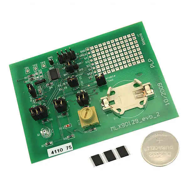
EVB90129
MLX90129 Evaluation Board Manual
Features
Application Examples
Versatile A/D interface for resistive
sensors
ISO15693 13.56MHz transponder
Slave / Master SPI interface
4 k-bit EEPROM with access protection
Standalone data-logging mode
Ultra low power
Battery or battery-less applications
Low cost and compact design
Asset management and monitoring
(security and integrity)
Building automation
Supply chain monitoring of temperature
and other parameters
Industrial, medical and residential
control
Ordering Information
Part No.
EVB90129
General Description
The EVB90129 is an assembled printed circuit board
that simplifies evaluation of the MLX90129 sensor tag
IC and to facilitate the development of wireless sensor
applications based on the MLX90129.
The EVB90129 was developed to demonstrate a wide
range of applications, from fully passive sensor tag
operation to complex data logging. Each of its
elements can be reconfigured by means of jumpers.
The board can be powered either by an external
voltage supply, the on-board battery or the
electromagnetic field from a RFID reader.
In addition to the internal temperature sensor of the
MLX90129, the EVB90129 embeds 3 external sensors,
light, temperature and potentiometer to demonstrate
the flexibility for measurement of a variety of physical
quantities. The custom prototyping area allows users
to integrate their own sensor or circuit into this
evaluation board.
The EVB90129 is capable of storing 128 Kbit of data's
in the SPI EEPROM memory connected to the
MLX90129.
The EVB90129 can be accessed and controlled through
a contactless (RFID) or a contact (SPI) interface. The
RFID access to the MLX90129 and the related
commands are compliant with the ISO15693 standard.
The SPI and other digital inputs/outputs from the
MLX90129 are connected to an 8-pin connector of the
REVISION 003 - JUNE 20, 2017
390129012901
EVB90129. This allows
microcontroller.
easy
connection
to
a
�EVB90129
MLX90129 Evaluation Board Manual
Contents
Features ..................................................................................................................................................... 1
Application Examples ................................................................................................................................. 1
Ordering Information ................................................................................................................................. 1
General Description ................................................................................................................................... 1
1. EVB90129 global description.................................................................................................................. 3
2. EVB90129 Power Supplies...................................................................................................................... 5
3. EVB90129 Communication..................................................................................................................... 5
3.1. External SPI connector ........................................................................................................................5
3.2. Slave Select selector............................................................................................................................6
3.3. RFID antenna .......................................................................................................................................7
3.4. Register Configuration ........................................................................................................................7
4. Sensor description ................................................................................................................................. 8
4.1. Internal temperature sensor ..............................................................................................................8
4.2. Light sensor .........................................................................................................................................8
4.3. External temperature sensor..............................................................................................................9
4.4. Potentiometer sensor .........................................................................................................................9
5. Miscellaneous peripheries ................................................................................................................... 10
5.1. Padlock or security device function ................................................................................................ 10
5.2. External SPI memory ........................................................................................................................ 10
5.3. External XTAL .................................................................................................................................... 10
5.4. Test points and patch area .............................................................................................................. 11
6. Using the EVB90129 ............................................................................................................................. 11
7. Schematic ............................................................................................................................................ 11
8. List of components............................................................................................................................... 12
9. Contact ................................................................................................................................................ 13
10. Disclaimer .......................................................................................................................................... 13
REVISION 003 - JUNE 20, 2017
390129012901
�EVB90129
MLX90129 Evaluation Board Manual
1. EVB90129 global description
The EVB90129 simplifies evaluating all the features of the MLX90129. The following application can be executed on the
EVB90129:
Sensor control via SPI (application with a microcontroller)
Passive sensor tag (sensor control via RFID without battery)
Automatic data logging of the three sensors values logged to the external memory
Automatic data logging of the three sensors values logged to the MLX90129 memory
External memory access via RFID
Padlock or security device function (antitheft system)
EVB90129 provides three ways to supply the MLX90129. A battery, an external voltage or the electromagnetic field can
be used.
There are two communication channels to communicate with MLX90129: SPI and RFID. The SPI signals are available
through the SPI connector and the RFID antenna has been tuned to match with the MLX90129 internal capacitance.
EVB90129 provides four sensors: the MLX90129 internal temperature sensor and three external sensors. The three
external sensors are composed of a light sensor, an external temperature sensor and one potentiometer. Another
sensor can be connected to the MLX90129 using the prototyping development area included on the EVB.
To store a large amount of data during data logging application, an external SPI memory is available.
The following diagram describes the principles of the EVB90129 and the following pictures describe the hardware
blocks.
Power Supply
selection
XOUT
XIN
SENSSUP2
Light
Sensor
VDD
VBAT
VFIELD
SENS1
SENS2
MLX90129
VREG
SENSSUP1
Temperature
Sensor
SENS3
SS
Serial SPI
EEPROM
SCK
MISO
Trimmer
Sensor
MOSI
SENS4
COIL1
COIL2
SPI
connector
EVB Antenna
REVISION 003 - JUNE 20, 2017
390129012901
�EVB90129
MLX90129 Evaluation Board Manual
EVB90129 Top – hardware block description
EVB90129 Bottom – hardware block description
REVISION 003 - JUNE 20, 2017
390129012901
�EVB90129
MLX90129 Evaluation Board Manual
1
0
0
6
5
n
0
0
D
N
0
0
1
n
D
N
G
1
BZV55/C4V7
2
C
D
VFIELD_29
G
1
VDD_Selector
C
1
Z
VDD_BAT
2
VBAT_29
The EVB90129 allows supplying the MLX90129 through three ways.
Power supply can be provided by a battery CR2032, by an external
power supply input or a by an electromagnetic field from a RFID
reader. The jumper CON2/ VDD_Selector allow selecting the
regulated source of power. This source is filtered by L1 and C5. C3
is not mounted. The energy from an applied electromagnetic field
is collected with the 13.56MHz tuned antenna through the pin
COIL1 and COIL2. A Zener diode on the VFIELD pin ensures the
compliance with the maximum electrical rating defined in the
MLX90129 datasheet. Indeed, very powerful reader could provide
enough energy to exceed this rating. The 100 nF capacitor C2 on
VFIELD pin allows storing of this energy in order to supply the
MLX90129 and the external sensor in sensor tag application.
L
3
VDD_SPI
CON2
2. EVB90129 Power Supplies
The following drawings show how to set jumpers in order to select
the power supply source
External power supply
Battery powered
Electromagnetic field powered
VDD selector
VDD selector
VDD selector
BAT
2
3
VDD_Jumper
CON2
3
1
2
VDD_Jumper
Board
Board
SPI
BAT
VDD_Jumper
1
1
SPI
CON2
3
2
Board
BAT
SPI
CON2
Board
Board
Board
Depending on the mode used, care should be taken about the internal MLX90129 switches for power management.
Please read the datasheet for more information on this topic.
3. EVB90129 Communication
The EVB90129 allows communication with the MLX90129 through SPI and RFID and also between the MLX90129 and an
external memory during a data logging application. The SPI signals are received through the SPI connector and the
SS_Selector allows selecting the communication channel. RFID signals are received through the RFID antenna connected
to the MLX90129.
REVISION 003 - JUNE 20, 2017
390129012901
SS_MCU
R
0
CON_SPI
D
N
G
E
R
V
8
R14
6
5
7
SCK
4
3
MISO
2
1
IRQ_29
VDD_SPI
MOSI
G
The digital Inputs/Outputs of the SPI bus and the IRQ pin of
the MLX90129 are available on the connector
CON1/CON_SPI. In addition the external SPI connector
provides pins to supply EVB90129 (VDD_SPI and GND), and a
connection to the Voltage Regulated output VREG. The
following table, schematic and diagram give information
about the SPI connector. Per default, the resistor R14 is not
mounted.
CON1
3.1. External SPI connector
�EVB90129
MLX90129 Evaluation Board Manual
Pin
I/O
Name
Description
1
Output
IRQ_29
Interrupt output
2
Input
SS_MCU
Slave Select signal of the SPI bus
3
Input
VDD_SPI
External power supply
4
Output
MISO
Master In Slave Out of the SPI bus
5
Input
MOSI
Master Out Slave In of the SPI bus
6
Input
SCK
Clock of the SPI bus
7
Input
GND
Ground of the EVB
8
Output
VREG
Regulated supply voltage from MLX90129*
*Not connected per default / R14 not mounted
2
SS
MISO
SCK
VREG
8
1
IRQ
VDD
SPI
MOSI
GND
7
9
2
_
S
S
External MCU as SPI-Master and MLX90129 as SPI-Slave
MLX90129 as SPI-Master and external memory as SPI-Slave (data
logging application)
External MCU as SPI-Master and external memory as SPI-Slave
SS_Selector
4
3
SS_MEM
2
1
SS_MCU
The CON4/SS_Selector allows switching between the several SPI devices on
the EVB. There are three communication channels:
CON4
3.2. Slave Select selector
By selecting the connection of the Slave Selects, the SPI communication channels are switched as shown in the following
schematic and draws.
External MCU MLX90129
MLX90129 External memory
SS selector
2
1
SS_Jumper
CON4
Board
REVISION 003 - JUNE 20, 2017
390129012901
4
3
Board
SS_29
2
1
CON4
Board
SS_MEM
4
3
SS_Jumper
Board
SS_29
2
1
CON4
SS_MCU
SS_29
SS_MEM
SS_MCU
3
Board
SS_Jumper
4
SS selector
SS selector
SS_MCU
SS_MEM
External MCUExternal memory
Board
�EVB90129
MLX90129 Evaluation Board Manual
3.3. RFID antenna
2
R
1
p
7
1
R
are
C1
and
R3
/!\
mounted
not
Mils
2020
x
2820
:
antenna
PCB
tunrs
three
/
Mils
15
=
space
/
Mils
30
=
uH
1.838
=
L
wire
Rectangular
TP2
0
COIL2
R
K
1
4
3
R
C
0
COIL1
R
TP1
The EVB antenna has been designed to work with a 13.56MHz electromagnetic field. The antenna can be directly
connected to the MLX90129 through pins COIL1 and COIL2. The Shortcut R1 and R2 allows for disconnecting the
antenna and R3 and C1 footprint (components not mounted) could be used to match MLX90129 with another antenna.
The following schematic and drawing show the antenna connection and the antenna shape:
2820 mil
7.16 cm
2020 mil
5.13 cm
30 mil
76 mm
120 mil
304 mm
Bottom view
2865 mil
7.28 cm
15 mil
38 mm
Bottom view
For information: 1 mil = 2.54E-3 cm
3.4. Register Configuration
There are a lot of possible configurations for enabling communication features. For example SPI or RFID access can be
disabled and EEPROM area or register file access can be restricted. The following configuration puts the MLX90129 in a
security free mode. The device is fully accessible by RFID and SPI. More information is available in the MLX90129
datasheet.
Content
EEPROM security
Device security
#
04
05
REVISION 003 - JUNE 20, 2017
390129012901
Hexa
AAA8
3FF0
15
1
0
14
0
0
13
1
1
12
0
1
11
1
1
10
0
1
9
1
1
8
0
1
7
1
1
6
0
1
5
1
1
4
0
1
3
1
0
2
0
0
1
0
0
0
0
0
�EVB90129
MLX90129 Evaluation Board Manual
4. Sensor description
EVB90129 is delivered with three external sensors in addition to the internal temperature sensor of the MLX90129; a
light sensor, an external temperature sensor and a potentiometer. For each sensor, the schematic and a configuration of
the MLX90129 register is provided. The sensors are provided as examples and have not been calibrated. The
configuration provided is basic, there is no amplification (per default gain=8), no threshold, and no offset with the DAC.
The ADC mode is “11”, the initialization time is minimal and there is no averaging so the chopper is disabled. The
datalogging control bits (b4, b5, b6) of the “Control word” are set. The MLX90129 datasheet provides more details
about the register configuration.
The basic following configuration for sensor conditioning can be used for all sensors.
Content
#
Hexa
15 14
Sensor power
12
00FF
0
0
Sensor trimming
14
0TT0
0
0
‘T’ means Melexis trimming bits. Do not change.
13
0
0
12
0
0
11
0
0
10
0
0
9
0
T
8
0
T
7
1
T
6
1
T
5
1
0
4
1
0
3
1
0
2
1
0
1
1
0
0
1
0
4.1. Internal temperature sensor
The specifications of the internal temperature sensor are available in the MLX90129 datasheet. The following register
configuration allows monitoring the full range of the internal temperature sensor.
#
15
16
17
18
19
1A
Hexa
C070
0000
0000
0000
0231
8000
15
1
0
0
0
0
1
14
1
0
0
0
0
0
13
0
0
0
0
0
0
12
0
0
0
0
0
0
11
0
0
0
0
0
0
10
0
0
0
0
0
0
9
0
0
0
0
1
0
8
0
0
0
0
0
0
7
0
0
0
0
0
0
6
1
0
0
0
0
0
7
0
0
0
0
0
0
6
1
0
0
0
0
0
5
1
0
0
0
1
0
4
1
0
0
0
1
0
3
0
0
0
0
0
0
2
0
0
0
0
0
0
1
0
0
0
0
0
0
0
0
0
0
0
1
0
2
0
0
0
0
0
0
1
0
0
0
0
0
1
0
0
0
0
0
0
0
3
1
#
15
16
17
18
19
1A
REVISION 003 - JUNE 20, 2017
390129012901
Hexa
C070
0000
0000
0000
0000
0002
15
1
0
0
0
0
0
14
1
0
0
0
0
0
13
0
0
0
0
0
0
12
0
0
0
0
0
0
11
0
0
0
0
0
0
10
0
0
0
0
0
0
9
0
0
0
0
0
0
R
R
0
7
1
4
1
0
0
0
0
0
R
R
5
1
0
0
0
0
0
D
0
8
0
0
0
0
0
0
N
G
Content
Control word
Low threshold
High threshold
Conditioner config.
Connection config.
Resistance network
0
The schematic shows the sensor implementation and the following register
configuration allows monitoring the ambient light on the phototransistor
through the MLX90129.
This sensor fits mainly for the sun light monitoring. The output voltage with
flashlight is very low.
6
2
TEPT5700
Q
1
LIGHT_SELECTOR
The light sensor is a phototransistor for ambient light sensor measurement.
To use, it, all the jumpers of the CON6/ LIGHT_SELECTOR have to be set in
order to connect MLX90129 pins SENSSUP2, SENS1 and SENS2 to the
sensor.
1
2
SENSSUP2
4
SENS1
6
4.2. Light sensor
5
SENS2
CON6
Content
Control word
Low threshold
High threshold
Conditioner config.
Connection config.
Resistance network
3
0
0
0
0
0
0
�EVB90129
MLX90129 Evaluation Board Manual
#
15
16
17
18
19
1A
Hexa
C070
0000
0000
0000
0123
0040
15
1
0
0
0
0
0
14
1
0
0
0
0
0
13
0
0
0
0
0
0
12
0
0
0
0
0
0
10
0
0
0
0
0
0
9
0
0
0
0
0
0
8
0
0
0
0
1
0
11
0
0
0
0
0
0
10
0
0
0
0
0
0
9
0
0
0
0
0
0
8
0
0
0
0
0
0
6
1
0
0
0
0
1
8
K
0
K
9
K
0
D
5
1
0
0
0
1
0
4
1
0
0
0
0
0
5
1
0
0
0
1
0
4
1
0
0
0
0
0
3
0
0
0
0
0
0
2
0
0
0
0
0
0
1
0
0
0
0
1
0
0
0
0
0
0
1
0
1
0
0
0
0
0
0
0
0
0
0
0
1
0
Content
Control word
Low threshold
High threshold
Conditioner config.
Connection config.
Resistance network
#
15
16
17
18
19
1A
REVISION 003 - JUNE 20, 2017
390129012901
Hexa
C070
0000
0000
0000
0069
0040
15
1
0
0
0
0
0
14
1
0
0
0
0
0
13
0
0
0
0
0
0
12
0
0
0
0
0
0
7
0
0
0
0
0
0
K
0
R10
6
1
0
0
0
1
1
R
0
0
R13
3
0
0
0
0
1
0
K
0
D
N
G
1
R11
3
1
2
1
1
TRIM_SELECTOR
2
The external trimmer is a 100 Ohm variable resistor. The
output voltage monitored by SENS 4 corresponds to SENSsUP1
divided per 2 plus the variation of the sensor. This voltage will
be compared with VCM (SENSSUP1 divided by 2) value
internally of the MLX90129. The datasheet gives more
information about this setup.
To be used, all the jumpers of the CON8/ TRIM_SELECTOR
have to be set in order to connect MLX90129 pins SENSSUP1
and SENS4 to the sensor. The schematic shows the sensor
implementation and the following register configuration
allows monitoring the variation of trimmer resistivity through
the MLX90129.
1
SENSSUP1
4
SENS4
CON8
4.4. Potentiometer sensor
7
0
0
0
0
0
0
N
G
1
R
°
1
t
R12
1
R
1
TEMP_SELECTOR
2
SENSSUP1
11
0
0
0
0
0
0
3
Content
Control word
Low threshold
High threshold
Conditioner config.
Connection config.
Resistance network
4
The external temperature sensor is a thermistor of 1KOhm
with an operating temperature range from -40 to +125
degrees Celsius. The output voltage monitored by SENS 3
corresponds to SENSSUP1 divided per 2 plus the variation of
the sensor. This voltage will be compared with VCM
(SENSSUP1 divided by 2) value internally of the MLX90129.
The datasheet gives more information about this setup. To be
used, all the jumpers of the CON7/ TEMP_SELECTOR have to
be set in order to connect MLX90129 pins SENSSUP1 and
SENS3 to the sensor. The schematic shows the sensor
implementation and the following register configuration
allows monitoring the ambient temperature through the
MLX90129.
3
SENS3
CON7
4.3. External temperature sensor
2
0
0
0
0
0
0
�MLX90129
4
G
E
R
V
5
8
Hexa
0A00
15
0
14
0
13
0
12
0
7
0
6
0
5
0
4
0
3
0
2
0
N
D
1
0
0
0
G
E
R
7
Vcc
pin
to
Close
Selector
Mem
n
0
0
D
N
MISO
2
Q
2
CAT25128
D
N
G
4
Vss
S
1
SS_MEM
W
3
HOLD
7
Vcc
U
C
6
SCK
D
5
MOSI
8
G
K
0
0
1
1
4
R
Ext
C
1
2
V
CON3
The MLX90129 can be connected to a SPI external memory in
order to store a large amount of data during a data logging
application. An external 128Kbit memory is available on the
EVB90129. It can be connected by setting the jumper CON3 /
ExtMemSelector. In this configuration, the external memory is
supplied by the regulated voltage output (VREG) of the
MLX90129. The SPI pins (SS / SCK / MISO /MOSI) are
connected to the MLX90129 SPI pins. The CON4 / SS_selector
allows connecting the SS pin of the MLX90129 to the SS pin of
the external memory. The schematic shows the memory
implementation and the following register configuration
allows the MLX90129 to communicate with the memory as a
SPI master. More information is available in the MLX90129
datasheet.
The SPI memory datasheet gives the following commands:
- Write Enable = 0x06
- Write Memory = 0x02
- Read Memory = 0x03
The MLX90129 has to be in SPI master mode. The bit 0 of the Device security register has to be set either in EEPROM
(restricted access by RFID) or in the register files.
#
0D
0E
05
Hexa
0639
0203
3FF1
15
0
0
0
14
0
0
0
13
0
0
1
12
0
0
1
11
0
0
1
10
1
0
1
9
1
1
1
8
0
0
1
7
0
0
1
6
0
0
1
5
1
0
1
4
1
0
1
REVISION 003 - JUNE 20, 2017
390129012901
XOUT
1
4
32K768
1
XIN
For Auto logging function an external precise clock can be used
to enhance timing between two sensor acquisitions. The
32,768 KHz crystal is connected between the pins XIN and
XOUT of the MLX90129. The bit 14 of the Internal Devices
Domain, address #03 has to be set.
Y
5.3. External XTAL
3
1
0
0
2
0
0
0
1
0
1
0
0
1
1
1
S
S
VSS
1
9
8
0
D
G
9
1
N
G
10
0
0
1
1
2
1
SCK
C
N
7
TP3
Black
CON13
2
1
Lock
Pad
11
1
5.2. External SPI memory
Content
Control word
Command codes
Device security
5
9
MISO
1
#
12
MOSI
The pin 7 of the MLX90129 can be used as a Padlock function,
else it has to be connected to the ground. The padlock
function allows generating an IRQ when the jumper between
pin 7 and the ground is removed.
The schematic shows the Padlock jumper implementation and
the following register configuration allows configuring the
MLX90129 in order to use this feature.
Content
Power configuration
6
SENSSUP1
1
SENSSUP2
1
IRQ
6
3
4
1
7
1
SENS1
SENS1
SENS2
8
SENS2
5.1. Padlock or security device function
1
SENS3
SENS3
SENS4
SENS4
5. Miscellaneous peripheries
1
XOUT
XOUT
XIN
XIN
VFIELD
3
VBAT
MLX90129 Evaluation Board Manual
T
U
D
VBAT_29
2
0
1
2
COIL1
COIL1
COIL2
COIL2
EVB90129
�EVB90129
MLX90129 Evaluation Board Manual
5.4. Test points and patch area
Name
Description
TP1
Coil1
Coil 1 pin
TP2
Coil2
Coil 2 pin
TP3
NC
Not used
TP4
GND
Ground
area
D
N
G
Patch
8
7
G
E
R
V
6
SENS4
5
SENS3
4
SENS2
3
SENS1
2
SENSSUP2
1
Test pins number
SENSSUP1
CON5
Some analogue outputs are foreseen on the evaluation board as test pins referenced from TP1 to TP4. These test pins can be
used to monitor signals. In order to connect other sensors to the MLX90129, a patch area is available. The following table
describes all test pins available and the following schematic shows the signals available on the patch area.
6. Using the EVB90129
The EVB90129 can be configured and controlled through its RFID and its SPI interface. Please refer to the MLX90129
Datasheet and the application notes for information about register configuration and command description. A bad
configuration can lock the MLX90129 communication completely. Care should be taken about the command sent and the
configuration applied. In order to avoid bad manipulation and to speed up the development, the MLX90129 development kit
is available (DVK90129). It contains the EVB90129, a USB RFID reader and user friendly software interface. Please refer to
our website (www.melexis.com) for more information.
7. Schematic
Schematic of the MLX90129 evaluation board:
Page 11 of 13
REVISION 003 - JUNE 20, 2017
390129012901
�EVB90129
MLX90129 Evaluation Board Manual
8. List of components
The table below gives an overview of all components that compose the evaluation board EVB90129.
Reference
BT1
BT2
C1*
C2
C3*
C5
C7
CON1
CON2
CON3
CON4
CON6
CON7
CON8
CON13
DUT
D1
L1
Q1
R1
R2
R3*
R4
R6
R7
R8
R9
R10
R11
R12
R13
R14*
R15*
TP1
TP2
TP3
TP4
U2
Y1
Value
3V
100nF
4u7 F
100nF
100nF
CON_SPI
VDD_Selector
Ext Mem Selector
SS_Selector
LIGHT_SELECTOR
TEMP_SELECTOR
TRIM_SELECTOR
Pad Lock
MLX90129
4.7V
Z600
TEPT5700
0R
0R
100K
100R
0R
10K
10K
10K
10K
1K
100R
0R
1M
Black
Black
Black
Black
M95128-WMN6P
32K768
Description
Battery Holder 1 x CR2032
Battery CR2032
Capacitor
Capacitor Multilayer Ceramic X7R 50V
Capacitor Tantalum 4.7uF; 16V;
Capacitor Multilayer Ceramic X7R 50V
Capacitor Multilayer Ceramic X7R 50V
Header, 2x4 pins, pitch 2.54mm, Male, Straight
Header, 1x3 pins, pitch 2.54mm, Male, Straight
Header, 1x2 pins, pitch 2.54mm, Male, Straight
Header, 2x2 pins, pitch 2.54mm, Male, Straight
Header, 2x3 pins, pitch 2.54mm, Male, Straight
Header, 2x2 pins, pitch 2.54mm, Male, Straight
Header, 2x2 pins, pitch 2.54mm, Male, Straight
Header, 1x2 pins, pitch 2.54mm, Male, Straight
MLX90129, soldered, TSSOP20
Zener diode
Ferrite Bead 1206; Z=600ohm/100MHz; Current=200mA
Phototransistor, Sensor, ambient light
Resistor Thick Film; 0R; 0805; 0.125W; 1%; 150V
Resistor Thick Film; 0R; 0805; 0.125W; 1%; 150V
Resistor
Resistor Thick Film; 100K; 0805; 0.125W; 1%; 150V
Resistor Thick Film; 100R; 0805; 0.125W; 1%; 150V
Resistor Thick Film; 0R; 0805; 0.125W; 1%; 150V
Resistor Thick Film; 10K; 0805; 0.125W; 1%; 150V
Resistor Thick Film; 10K; 0805; 0.125W; 1%; 150V
Resistor Thick Film; 10K; 0805; 0.125W; 1%; 150V
Resistor Thick Film; 10K; 0805; 0.125W; 1%; 150V
Thermistor; 1K, 0805, 0.1W, 5%, 50V, TCR=3000ppm/DegC
POTENTIOMETER; 100R, 0.5W, 10%, 300Vdc, turns=1
Resistor
Resistor
Test Terminal, BLACK; Head=1.3mm
Test Terminal, BLACK; Head=1.3mm
Test Terminal, BLACK; Head=1.3mm
Test Terminal, BLACK; Head=1.3mm
128Kbit Serial SPI Bus EEPROM
Quartz Crystal MD 6.9x1.4x1.3mm; 32.768kHz, 20ppm
* Components not mounted
Page 12 of 13
REVISION 003 - JUNE 20, 2017
390129012901
�EVB90129
MLX90129 Evaluation Board Manual
9. Contact
For the latest version of this document, go to our website at www.melexis.com.
For additional information, please contact our Direct Sales team and get help for your specific needs:
Europe, Africa
Telephone: +32 13 67 04 95
Email : sales_europe@melexis.com
Americas
Telephone: +1 603 223 2362
Email : sales_usa@melexis.com
Asia
Email : sales_asia@melexis.com
10. Disclaimer
The information furnished by Melexis herein (“Information”) is believed to be correct and accurate. Melexis disclaims (i) any and all liability in connection with or arising out of the
furnishing, performance or use of the technical data or use of the product(s) as described herein (“Product”) (ii) any and all liability, including without limitation, special,
consequential or incidental damages, and (iii) any and all warranties, express, statutory, implied, or by description, includ ing warranties of fitness for particular purpose, noninfringement and merchantability. No obligation or liability shall arise or flow out of Melexis’ rendering of technical or other services.
The Information is provided "as is” and Melexis reserves the right to change the Information at any time and without notice. Therefore, before placing orders and/or prior to
designing the Product into a system, users or any third party should obtain the latest version of the relevant information to verify that the information being relied upon is current.
Users or any third party must further determine the suitability of the Product for its application, including the level of reliability required and determine whether it is fit for a
particular purpose.
The Information is proprietary and/or confidential information of Melexis and the use thereof or anything described by the In formation does not grant, explicitly or implicitly, to
any party any patent rights, licenses, or any other intellectual property rights.
This document as well as the Product(s) may be subject to export control regulations. Please be aware that export might require a prior authorization from competent authorities.
The Product(s) are intended for use in normal commercial applications. Unless otherwise agreed upon in writing, the Product(s) are not designed, authorized or warranted to be
suitable in applications requiring extended temperature range and/or unusual environmental requirements. High reliability applications, such as medical life-support or lifesustaining equipment are specifically not recommended by Melexis.
The Product(s) may not be used for the following applications subject to export control regulations: the development, product ion, processing, operation, maintenance, storage,
recognition or proliferation of 1) chemical, biological or nuclear weapons, or for the development, production, maintenance o r storage of missiles for such weapons: 2) civil
firearms, including spare parts or ammunition for such arms; 3) defense related products, or other material for military use or for law enforcement; 4) any applications that, alone
or in combination with other goods, substances or organisms could cause serious harm to persons or goods and that can be used as a means of violence in an armed conflict or any
similar violent situation.
The Products sold by Melexis are subject to the terms and conditions as specified in the Terms of Sale, which can be found at https://www.melexis.com/en/legal/terms-andconditions.
This document supersedes and replaces all prior information regarding the Product(s) and/or previous versions of this document.
Melexis NV © - No part of this document may be reproduced without the prior written consent of Melexis. (2016)
ISO/TS 16949 and ISO14001 Certified
Page 13 of 13
REVISION 003 - JUNE 20, 2017
390129012901
�