MLX90364LVS-ADD-201-RE 数据手册
MLX90364 Triaxis® Position Sensor
Datasheet
Absolute Rotary & Linear Position Sensor IC
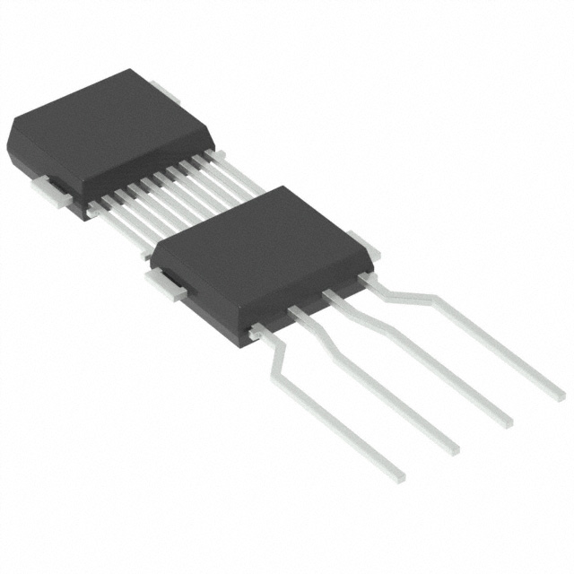
Robust Dual Mold Package (DMP-4) feat. up to
4 Decoupling Capacitors (ESD/EMC)
Reliable NoPCB Module Integration
Triaxis Hall Technology
Simple Magnetic Design
Programmable Transfer Characteristic (MultiPoints – Piece-Wise-Linear)
Selectable Output Mode: Analog (Ratiometric)
– Pulse Width Modulation (PWM)
12 bit Resolution - 10 bit Thermal Accuracy
Open/Short Diagnostics
On Board Diagnostics
Over-Voltage Protection
Under-Voltage Detection
48 bit ID Number option
Automotive Temperature Range
AEC-Q100 & AEC-Q200 Qualified
DMP-4 RoHS Compliant
Output Thermal Offset correction
DMP-4
Applications
Absolute Rotary Position Sensor
Absolute Linear Position Sensor
EGR Valve Position Sensor
Turbo Actuator
Throttle Position Sensor
Clutch, Shift & Fork Position Sensor
Ride Height Position Sensor
Float Level Sensor
Description
The MLX90364 Triaxis® Position Sensor Assembly
is a high accuracy linear and angular position
sensor which eliminates need for inclusion of a
printed circuit board (PCB) within sensing
modules.
This device is based on a Dual Mold Package
(DMP-4) construction, which integrates a Triaxis
position sensing die together with the decoupling
capacitors necessary to meet the strenuous ESD
and EMC requirements. No PCB is needed.
The Triaxis position sensing die is nothing but the
one used for the MLX90365 in conventional
surface-mount packages (SOIC-8 and TSSOP-16).
Similarly to other Triaxis products, the MLX90364
is sensitive to the flux density applied
orthogonally and parallel to the IC surface i.e. the
3 components of the flux density applied to the IC
(i.e. BX, BY and BZ). This allows the MLX90364 with
the correct magnetic circuit to decode the
absolute position of any moving magnet (e.g.
rotary position from 0 to 360 Degrees or linear
displacement, stroke).
MLX90364 reports a programmable ratiometric
analog output signal compatible with any resistive
potentiometer or programmable linear Hall
sensor. Through programming, the MLX90364
provides also a digital PWM (Pulse Width
Modulation) output characteristic.
VDD
VDIG
Prot.
2V5
Reg
DSP
Triaxis®
VX
VY
VZ
EEPROM
RAM
MUX
Features and Benefits
G
ADC
Output Stage
12 bit Analog
µC
OUT
12 bit PWM
ROM - Firmware
VSS
�MLX90364 Triaxis® Position Sensor
Datasheet
Contents
Features and Benefits................................................................................................................................... 1
Applications .................................................................................................................................................. 1
Description ................................................................................................................................................... 1
1. Ordering Information ............................................................................................................................... 5
2. Functional Diagram .................................................................................................................................. 8
3. Glossary of Terms ..................................................................................................................................... 8
4. Pinout ....................................................................................................................................................... 9
5. Absolute Maximum Ratings ...................................................................................................................... 9
6. Electrical Specification ............................................................................................................................ 10
7. Timing Specification................................................................................................................................ 13
7.1. ANALOG OUTPUT ........................................................................................................................... 13
7.2. PWM OUTPUT ................................................................................................................................ 14
8. Accuracy Specification ............................................................................................................................ 15
8.1. Magnetic Accuracy ......................................................................................................................... 15
8.1.1. Normal Magnetic range: 20 mT ≤ B < 70 mT........................................................................... 15
8.1.2. Extended Range #1 : 15 mT ≤ B < 20 mT ................................................................................ 16
8.1.3. Extended Range #2: 10 mT ≤ B < 15 mT ................................................................................. 16
8.2. ANALOG OUTPUT ........................................................................................................................... 17
8.3. PWM OUTPUT ................................................................................................................................ 18
9. Magnetic Specification ........................................................................................................................... 20
10. CPU & Memory Specification ............................................................................................................... 20
11. Traceability Information ....................................................................................................................... 21
12. End-User Programmable Items ............................................................................................................ 21
13. Description of End-User Programmable Items ..................................................................................... 23
13.1. Output modes .............................................................................................................................. 23
13.1.1. OUT mode .............................................................................................................................. 23
13.1.2. Analog Output Mode ............................................................................................................. 24
13.1.3. PWM Output Mode ............................................................................................................... 24
13.2. Output Transfer Characteristic .................................................................................................... 25
13.2.1. Enable scaling Parameter (only for LNR type 4 pts) .............................................................. 26
13.2.2. CLOCKWISE Parameter .......................................................................................................... 26
REVISION 007 – OCT 2018
390109036401
Page 2 of 45
�MLX90364 Triaxis® Position Sensor
Datasheet
13.2.3. Discontinuity Point (or Zero Degree Point) ........................................................................... 26
13.2.4. 4-Pts LNR Parameters ............................................................................................................ 26
13.2.5. 17-Pts LNR Parameters .......................................................................................................... 27
13.2.6. CLAMPING Parameters .......................................................................................................... 28
13.2.7. Thermal Output Offset correction (AxE version only) ........................................................... 28
13.3. Identification ................................................................................................................................ 29
13.4. Lock .............................................................................................................................................. 29
13.5. Sensor Front-End ......................................................................................................................... 30
13.5.1. MAPXYZ .................................................................................................................................. 30
13.5.2. SMISM, k and SEL_k Parameters ........................................................................................... 30
13.5.3. GAINMIN and GAINMAX Parameters .................................................................................... 31
13.6. Filter ............................................................................................................................................. 31
13.6.1. Hysteresis Filter ...................................................................................................................... 31
13.6.2. FIR Filters ................................................................................................................................ 31
13.7. Programmable Diagnostic Settings.............................................................................................. 32
13.7.1. DIAG mode ............................................................................................................................. 32
13.7.2. DIAG Level .............................................................................................................................. 32
13.7.3. Field Strength Diagnostic ....................................................................................................... 32
13.7.4. PWM Diagnostic ..................................................................................................................... 33
13.7.5. Diagnostic Features................................................................................................................ 33
13.8. EEPROM endurance ..................................................................................................................... 33
14. Self Diagnostic ...................................................................................................................................... 34
15. Built-in Capacitors and Recommended Application Diagrams ............................................................. 38
16. Standard information regarding manufacturability of Melexis products with different soldering
processes ............................................................................................................................................... 39
17. ESD Precautions.................................................................................................................................... 39
18. Package Information............................................................................................................................. 40
18.1. DMP-4 Package ............................................................................................................................ 40
18.1.1. DMP-4 - Package Outline Dimensions (POD) – Straight Leads.............................................. 40
18.1.2. DMP-4 - Package Outline Dimensions (POD) – STD1 2.54 .................................................... 41
18.1.3. DMP-4 - Package Outline Dimensions (POD) – STD2 2.54 .................................................... 41
18.1.4. DMP-4 - Package Outline Dimensions (POD) – STD4 2.54 .................................................... 42
18.1.5. DMP-4 - Marking .................................................................................................................... 42
REVISION 007 – OCT 2018
390109036401
Page 3 of 45
�MLX90364 Triaxis® Position Sensor
Datasheet
18.1.6. DMP-4 - Sensitive Spot Positioning ....................................................................................... 43
18.1.7. DMP-4 - Angle detection ....................................................................................................... 44
19. Disclaimer ............................................................................................................................................. 45
20. Contact ................................................................................................................................................. 45
REVISION 007 – OCT 2018
390109036401
Page 4 of 45
�MLX90364 Triaxis® Position Sensor
Datasheet
1. Ordering Information
Product Code
Packing
Comment
Form
Temperature
Package
Option Code
MLX90364
L
VS
ADB-200
RE/RX
Not recommended for new design
MLX90364
L
VS
ADB-201
RE/RX
Not recommended for new design
MLX90364
L
VS
ADB-203
RE/RX
Not recommended for new design
MLX90364
L
VS
ADB-208
RE/RX
Not recommended for new design
MLX90364
L
VS
ADB-250
RE/RX
Not recommended for new design
MLX90364
L
VS
ADB-251
RE/RX
Not recommended for new design
MLX90364
L
VS
ADB-253
RE/RX
Not recommended for new design
MLX90364
L
VS
ADB-258
RE/RX
Not recommended for new design
MLX90364
L
VS
ADD-200
RE/RX
Not recommended for new design
MLX90364
L
VS
ADD-201
RE/RX
Not recommended for new design
MLX90364
L
VS
ADD-203
RE/RX
Not recommended for new design
MLX90364
L
VS
ADD-208
RE/RX
Not recommended for new design
MLX90364
L
VS
ADD-250
RE/RX
Not recommended for new design
MLX90364
L
VS
ADD-251
RE/RX
Not recommended for new design
MLX90364
L
VS
ADD-253
RE/RX
Not recommended for new design
MLX90364
L
VS
ADD-258
RE/RX
Not recommended for new design
MLX90364
L
VS
ADD-300
RE/RX
Not recommended for new design
MLX90364
L
VS
ADD-301
RE/RX
Not recommended for new design
MLX90364
L
VS
ADD-303
RE/RX
Not recommended for new design
MLX90364
L
VS
ADD-308
RE/RX
Not recommended for new design
MLX90364
L
VS
ADD-400
RE/RX
Not recommended for new design
MLX90364
L
VS
ADD-401
RE/RX
Not recommended for new design
MLX90364
L
VS
ADD-403
RE/RX
Not recommended for new design
MLX90364
L
VS
ADD-408
RE/RX
Not recommended for new design
MLX90364
L
VS
ADE-200
RE/RX
Not recommended for new design
MLX90364
L
VS
ADE-201
RE/RX
Not recommended for new design
MLX90364
L
VS
ADE-203
RE/RX
Not recommended for new design
REVISION 007 – OCT 2018
390109036401
Page 5 of 45
�MLX90364 Triaxis® Position Sensor
Datasheet
Product Code
Packing
Comment
Form
Temperature
Package
Option Code
MLX90364
L
VS
ADE-208
RE/RX
MLX90364
L
VS
AED-200
RE/RX
MLX90364
L
VS
AED-201
RE/RX
MLX90364
L
VS
AED-203
RE/RX
MLX90364
L
VS
AED-208
RE/RX
MLX90364
L
VS
AED-250
RE/RX
MLX90364
L
VS
AED-251
RE/RX
MLX90364
L
VS
AED-253
RE/RX
MLX90364
L
VS
AED-258
RE/RX
MLX90364
L
VS
AED-300
RE/RX
MLX90364
L
VS
AED-301
RE/RX
MLX90364
L
VS
AED-303
RE/RX
MLX90364
L
VS
AED-308
RE/RX
MLX90364
L
VS
AED-400
RE/RX
MLX90364
L
VS
AED-401
RE/RX
MLX90364
L
VS
AED-403
RE/RX
MLX90364
L
VS
AED-408
RE/RX
MLX90364
L
VS
AEE-200
RE/RX
MLX90364
L
VS
AEE-201
RE/RX
MLX90364
L
VS
AEE-203
RE/RX
MLX90364
L
VS
AEE-208
RE/RX
REVISION 007 – OCT 2018
390109036401
Not recommended for new design
Not recommended for new design
Not recommended for new design
Not recommended for new design
Not recommended for new design
Not recommended for new design
Page 6 of 45
�MLX90364 Triaxis® Position Sensor
Datasheet
Legend:
Temperature Code:
L: from -40 Deg.C to 150 Deg.C
Package Code:
“VS” for DMP-4
Option Code:
Axx-xxx: die version
ADx-xxx: not recommended for new design
AED-xxx: standard version
AEE-xxx: standard version with thermal offset correction
xxx-123:
12: Capacitances configuration see section 15.1
3: Trim-and-Form for DMP-4
Packing Form:
0: Standard straight leads. See section 18.1.1
1: Trim-and-Form STD1 2.54. See section 18.1.2 (not recommended for new
design, prefer STD4 2.54)
3: Trim-and-Form STD2 2.54. See section 18.1.3
8: Trim-and-Form STD4 2.54. See section 18.1.4
RE for Reel (face-up)
RX for Reel (face down)
SP Sample Pack
Ordering Example:
REVISION 007 – OCT 2018
390109036401
MLX90364LVS-AED-201-RE
Page 7 of 45
�MLX90364 Triaxis® Position Sensor
Datasheet
2. Functional Diagram
VDD
VDIG
Prot.
2V5
Reg
DSP
VX
VY
VZ
RAM
MUX
Triaxis
®
G
ADC
EEPROM
Output Stage
12 bit Analog
µC
OUT
12 bit PWM
ROM - Firmware
VSS
Figure 1 – Block Diagram
3. Glossary of Terms
Gauss (G),
Tesla (T)
TC
NC
ADC
LSB
MSB
DNL
INL
RISC
ASP
DSP
ATAN
IMC
Units for the magnetic flux density - 1 mT
= 10 G
Temperature Coefficient (in ppm/Deg.C.)
Not Connected
Analog-to-Digital Converter
Least Significant Bit
Most Significant Bit
Differential Non-Linearity
Integral Non-Linearity
Reduced Instruction Set Computer
Analog Signal Processing
Digital Signal Processing
Trigonometric function: arctangent (or
inverse tangent)
Integrated Magneto-Concentrator (IMC®)
CoRDiC
EMC
FE
RE
FW
HW
PWM
%DC
MT3V
MT4V
LSD
PP
Coordinate Rotation Digital Computer
(i.e. iterative rectangular-to-polar
transform)
Electro-Magnetic Compatibility
Falling Edge
Rising Edge
Firmware
Hardware
Pulse Width Modulation
Ratio Ton / Tperiod where Ton is the high
state duration and Tperiod is the duration
of 1 pwm period
More Than 3V Condition
More Than 4V Condition
Low Side Driver = Open drain N
Push-Pull
Table 1 – Glossary of Terms
REVISION 007 – OCT 2018
390109036401
Page 8 of 45
�MLX90364 Triaxis® Position Sensor
Datasheet
4. Pinout
PIN
Pin Name
1
VSS (Ground)
2
VDD
3
OUT
4
VSS (Ground)
5. Absolute Maximum Ratings
Parameter
Value
Supply Voltage, VDD (overvoltage)
+ 24 V
Reverse Voltage Protection
− 12 V (breakdown at -14 V)
Positive Output Voltage
+ 18 V (breakdown at 24 V)
Output Current (IOUT)
+ 30 mA (in breakdown)
Reverse Output Voltage
− 0.3 V
Reverse Output Current
− 50 mA (in breakdown)
Operating Ambient Temperature Range, TA
− 40 … + 150 Deg.C
Storage Temperature Range, TS
− 40 … + 150 Deg.C
Magnetic Flux Density
±1T
Exceeding the absolute maximum ratings may cause permanent damage. Exposure to absolute maximumrated conditions for extended periods may affect device reliability. These max ratings are guaranteed by
mean of a qualification test where the device is supplied at 24V for 48h, the Output voltage is supplied at
18V for 48h and the device is reversely supplied at -12V for 1h.
REVISION 007 – OCT 2018
390109036401
Page 9 of 45
�MLX90364 Triaxis® Position Sensor
Datasheet
6. Electrical Specification
DC Operating Parameters at Nominal Supply Voltage (unless otherwise specified) and for TA as specified by
the Temperature suffix (L).
Parameter
Symbol
Nominal Supply Voltage
(1)
Supply Current
IDD
Ipeak
Isurge Current(4)
Isurge
Power-On reset
Hysteresis
Min
Typ
Max
Units
4.5
5
5.5
V
Power saving Enabled
6
10(2)
Power saving Disabled
8
12
Peak current in PWM mode 7
30
40
mA
20
mA
2.5
V
200
mV
4.2
V
200
mV
6.6
V
200
mV
Vout = 0 V
15
mA
Vout = 5 V
15
mA
Vout = 18 V (TA = 25 Deg.C)
18
mA
VDD
Supply Current (PWM
mode) (3)
Power-On reset (rising)
Test Conditions
HPOR_LH
Refer to internal voltage Vdig
2
2.25
HPOR_Hyst
50
MT4V LH
3.8
Start-up Hysteresis
MT4V Hyst
50
PTC Entry Level (rising)
MT7V_LH
5.8
MT7V_Hyst
50
Start-up Level (rising)
PTC Entry Level
Hysteresis
Output Short Circuit
Current
ISHORT
Output Load Analog
RL
Output Load PWM
RL_PWM
Pull-down to Ground
Pull-up to 5V
4.0
6.2
mA
4.7(5)
10
kΩ
(5)
10
kΩ
4.7
Pull-down to Ground
1
kΩ
Pull-up to 5V
1
kΩ
1
For the dual version, the supply current is multiplied by 2.
To reach 10mA, the power saving option should be enabled. This option switches off and on internal blocks dynamically. It can be
disabled in case of extreme emission requirements or if an analog output is required with a resistor on either supply or output line.
3
This current is due to the charge of output capacitors in PWM push-pull mode.
4
The specified value is valid during early start-up time only; the current might dynamically exceed the specified value, shortly,
during the Start-up phase.
5
The minimum specified value is mandatory to reach passive diagnostic output levels. A minimum 1k load resistor can be used
otherwise.
2
REVISION 007 – OCT 2018
390109036401
Page 10 of 45
�MLX90364 Triaxis® Position Sensor
Datasheet
Parameter
Analog Saturation Output
Level
Symbol
Vsat_lo
Vsat_hi
Digital Saturation Level
Open drain Output
Vo_min
(RL_PWM to VPU(6))
Active Diagnostic Output
Level
Dsat_lo
Digital Saturation Output
Level
Dsat_hi
Test Conditions
Min
Typ
Max
Pull-up load RL ≥ 10 kΩ to 5 V
0.5
2
Pull-up load RL ≥ 5 kΩ to 18V
2
3
Pull-down load RL ≥ 5 kΩ
95
97
Pull-down load RL ≥ 10 kΩ
97.5
98.5
Pull-up load RL_PWM ≤ 1 kΩ to 5V
98
Pull-up load RL_PWM ≤ 1 kΩ to 14V
95
Pull-up load RL_PWM ≤ 1 kΩ to 18V
90
Pull-up load RL_PWM ≤ 5.6 kΩ to 5V
96
Pull-up load RL_PWM ≤ 5.6 kΩ to 14V
85
Pull-up load RL_PWM ≤ 5.6 kΩ to 18V
73
Units
%VDD
%VDD
%VPU(6)
Pull-up load RL ≥ 10 kΩ to 5V
0.5
2
Pull-up load RL ≥ 5 kΩ to 18V
2
3
Pull-down load RL ≥ 5 kΩ
95
97
Pull-down load RL ≥ 10 kΩ
97.5
98.5
%VDD
%VDD
Broken VSS &
BVSSPD
Passive Diagnostic
Output Level
BVSSPU
(Broken Track Diagnostic)
(7)
BVDDPD
BVDDPU
Digital output Ron
Clamped Output Level
Ron
Pull-down load RL ≥ 5 kΩ
95
Pull-down load RL ≥ 10 kΩ
97.5
Broken VSS &
Pull-up load RL ≥ 1kΩ
99.5
Broken VDD &
%VDD
100
0
Pull-down load RL ≥ 1kΩ
Broken VDD &
Pull-up load RL ≥ 5kΩ
%VDD
0.5
%VDD
2
%VDD
Diag_Low
15
30
Diag_Hi
120
300
Ω
Clamp_lo
Programmable
0
100
%VDD (8)
Clamp_hi
Programmable
0
100
%VDD (8)
6
VPU being the pull-up voltage connected externally to the output through the pull-up resistor
For detailed information on diagnostics, see also section Self Diagnostic
8
Clamping levels need to be considered vs the saturation of the output stage (see Vsat_lo and Vsat_hi)
7
REVISION 007 – OCT 2018
390109036401
Page 11 of 45
�MLX90364 Triaxis® Position Sensor
Datasheet
As an illustration of the previous table, the MLX90364 fits the typical classification of the output span
described on the Figure 2.
100 %
90 %
96 %
92 %
88 %
Diagnostic Band (High)
Clamping High
80 %
Output Level
70 %
60 %
Linear Range
50 %
40 %
30 %
20 %
10 %
0%
12 %
8%
4%
Clamping Low
Diagnostic Band (Low)
Figure 2 – Example of Output Span Classification for typical application
REVISION 007 – OCT 2018
390109036401
Page 12 of 45
�MLX90364 Triaxis® Position Sensor
Datasheet
7. Timing Specification
7.1. ANALOG OUTPUT
DC Operating Parameters at Nominal Supply Voltage (unless otherwise specified) and for TA as specified by
the Temperature suffix (L).
Parameter
Main Clock Frequency
Symbol
Ck
Main Clock Frequency Thermal
Drift
∆TCk
Refresh Rate
tper
Test Conditions
Min
Typ
Max
Units
12.6
13.3
14
MHz
± 3%
CkNOM
290
305
μs
657(10)
896
Filter=1
876
1195
Filter=2
1095
1494
118
121.5
All contributors (trimming
accuracy, supply voltage, thermal
and ageing)
275
Filter=0(9)
Step Response Time
Ts
Watchdog
Twd
Phase Shift
PS
Filter=0
Start-up Cycle
Tsu
Analog OUT Slew-rate excluded
Analog OUT Slew-rate
9
114.5
Analog Mode 1
0.16
37
ms
Deg/Hz
5
25
μs
ms
V/ms
See section 13.6 for details concerning Filter parameter
This represents a theoretical average response time
10
REVISION 007 – OCT 2018
390109036401
Page 13 of 45
�MLX90364 Triaxis® Position Sensor
Datasheet
7.2. PWM OUTPUT
DC Operating Parameters at Nominal Supply Voltage VDD
specified by the Temperature suffix (L).
Parameter
Symbol
FPWM
PWM Frequency
=
VPU (unless otherwise specified) and for TA as
Test Conditions
Max
Units
1000
Hz
Initial Tolerance (25 Deg.C)
± 2%
FPWM
After EOL tuning (25 Deg.C)
± 1%
FPWM
Thermal/Lifetime drift
± 3%
FPWM
Programmable Range
(PWM Output Enabled)
Min
Typ
100
PWM OUT Slew-rate excluded
Start-up Cycle
Tsu
100Hz
11.8
13
250Hz
5.8
7
1000Hz
5.8
7
80
130
μs
27
50
μs
27
50
μs
27
50
μs
ms
LOW SIDE DRIVER – Mode 5
Digital Output Rise Time
RL = 1 kΩ PU
PUSH-PULL – Mode 7
RL = 1 kΩ PU
LOW SIDE DRIVER – Mode
Digital Output Fall Time
RL = 1 kΩ PU
PUSH-PULL – Mode 7
RL = 1 kΩ PU
REVISION 007 – OCT 2018
390109036401
Page 14 of 45
�MLX90364 Triaxis® Position Sensor
Datasheet
8. Accuracy Specification
8.1. Magnetic Accuracy
8.1.1. Normal Magnetic range: 20 mT ≤ B < 70 mT
DC Operating Parameters at Nominal Supply Voltage (unless otherwise specified) and for TA as specified by
the Temperature suffix (L).
Parameter
Symbol
Thermal Offset Drift #1(11)
at the DSP input (excl. DAC
and output stage)
Thermal Drift of Sensitivity
Mismatch(12)
Min
Max
Units
TA from -40 to 125 Deg.C
-60
+60
LSB15
TA from -40 to 150 Deg.C
-90
+90
LSB15
XY axis
- 0.5
+ 0.5
-1
+1
TA = 25 Deg.C – XY axis
-0.3
0.3
TA = 25 Deg.C – XZ axis
-2
2
TA = 25 Deg.C – YZ axis
-2
2
XZ (YZ) axis
Magnetic Angle phase error
Thermal Drift of Magnetic
Angle phase error
XY – Intrinsic Linearity
Error(13)
Test Conditions
XY axis, XZ (YZ) axis
Typ
0.01
Le
TA = 25 Deg.C – factory trim.
“SMISM”
XZ - Intrinsic Linearity
Error(13)
Le
TA = 25 Deg.C – “k” trimmed for
XZ
-2.5
YZ - Intrinsic Linearity
Error(13)
Le
TA = 25 Deg.C – “k” trimmed for
YZ
-2.5
-1
%
Deg.
Deg.
1
Deg.
±1.25
+2.5
Deg.
±1.25
+2.5
Deg.
11
For instance, in case of a rotary position sensor application, Thermal Offset Drift #1 equal ± 60LSB15 yields to max. ± 0.3 Deg.
angular error for the computed angular information (output of the DSP). This is only valid if k = 1.
12
For instance, in case of a rotary position sensor application, Thermal Drift of Sensitivity Mismatch equal ± 0.5% yields to max. ±
0.15 Deg. angular error for the computed angular information (output of the DSP). See “MLX90364 Front-End Application Note” for
more details.
13
The Intrinsic Linearity Error refers to the IC itself (offset, sensitivity mismatch, orthogonality) taking into account an ideal rotating
field for BX and BY. Once associated to a practical magnetic construction and the associated mechanical and magnetic tolerances,
the output linearity error increases. However, it can be improved with the multi-point end-user calibration. The intrinsic Linearity
Error for Magnetic angle ∠XZ and ∠YZ can be reduced through the programming of the k factor.
REVISION 007 – OCT 2018
390109036401
Page 15 of 45
�MLX90364 Triaxis® Position Sensor
Datasheet
Parameter
Symbol
(14)
Noise pk-pk
Test Conditions
Min
Typ
Max
Filter = 0, 40mT
0.10
0.2
Filter = 1 (recommended), 30mT
0.10
0.2
Filter = 2, 20mT
0.10
0.2
Units
Deg.
8.1.2. Extended Range #1 : 15 mT ≤ B < 20 mT
DC Operating Parameters at nominal supply voltage (unless otherwise specified) and for TA as specified by
the Temperature suffix (L).
Parameter
Symbol
Test Conditions
Min
Offset on Raw Signals X,Y,Z
X0,Y0,Z0
TA = 25 Deg.C.
Thermal Offset Drift #1
Typ
Max
Units
-120
+120
LSB15
at the DSP input (excl. DAC
and output stage)
TA from -40 to 125 Deg.C
-120
+120
TA from -40 to 150 Deg.C
-180
+180
Noise pk-pk
Filter 0
75
LSB15
LSB15
In case of the use of the MLX90364 in those extended ranges, Melexis recommends validating the headroom
of the internal diagnostic and if necessary to disable the diagnostic mode related to the amplitude of the
flux strength and/or amplification factor of the device.
8.1.3. Extended Range #2: 10 mT ≤ B < 15 mT
DC Operating Parameters at nominal supply voltage (unless otherwise specified) and for TA as specified by
the Temperature suffix (L).
Parameter
Symbol
Test Conditions
Min
Offset on Raw Signals X,Y,Z
X0,Y0,Z0
TA = 25 Deg.C.
Thermal Offset Drift #1
Typ
Max
Units
-180
+180
LSB15
at the DSP input (excl. DAC
and output stage)
TA from -40 to 125 Deg.C
-180
+180
TA from -40 to 150 Deg.C
-270
+270
Noise pk-pk
Filter 0
112
LSB15
LSB15
In case of the use of the MLX90364 in those extended ranges, Melexis recommends to validate the
headroom of the internal diagnostic and if necessary to disable the diagnostic mode related to the
amplitude of the flux strength and/or amplification factor of the device.
14
Noise pk-pk (peak-to-peak) is here intended as 6 times the Noise standard Deviation. The application diagram used is described in
the recommended wiring. For detailed information, refer to section Filter in application mode (Section 13.6).
REVISION 007 – OCT 2018
390109036401
Page 16 of 45
�MLX90364 Triaxis® Position Sensor
Datasheet
8.2. ANALOG OUTPUT
DC Operating Parameters at nominal supply voltage (unless otherwise specified) and for TA as specified by
the Temperature suffix (L).
Parameter
ADC Resolution on the raw
signals sine and cosine(15)
Symbol
Test Conditions
Min
RADC
-0.2
(DAC and Output Stage)
12b DAC (Theoretical, Noise
free)
RDAC
INL (before EOL calibration)
DNL
Output stage Noise
Ratiometry Error
15
Max
15
Thermal Offset Drift #2
Analog Output Resolution
Typ
bits
+0.2
0.05
Clamped Output
%VDD
%VDD/
LSB12
0.025
-4
Units
+4
LSB12
1
3
LSB12
0.05
0.075
%VDD
4.5V ≤ VDD ≤ 5.5V
-0.05
+0.05
LT4V ≤ VDD ≤ MT7V
-0.1
+0.1
%VDD
16 bits corresponds to 15 bits + sign. Internal computation is performed using 16 bits.
REVISION 007 – OCT 2018
390109036401
Page 17 of 45
�MLX90364 Triaxis® Position Sensor
Datasheet
8.3. PWM OUTPUT
DC Operating Parameters at nominal supply voltage (unless otherwise specified) and for TA as specified by
the Temperature suffix (L).
Parameter
Symbol
PWM Output
Resolution
RPWM
Test Conditions
12 bits
Min
Typ
Max
Units
%DC/
0.025
LSB
LOW SIDE DRIVER – Mode5
±0.075
%DC
±0.075
%DC
±0.05
±0.2
Hz
±0.05
±0.2
Hz
100Hz, RL = 1 kΩ PU
±0.02
±0.03
%DC
200Hz, RL = 1 kΩ PU
±0.02
±0.03
%DC
100Hz, RL = 1 kΩ PU
±0.02
±0.03
%DC
200Hz, RL = 1 kΩ PU
±0.02
±0.03
%DC
200Hz, RL = 1 kΩ PU
PWM % DC Jitter
(16)
±0.015
JDC
PUSH-PULL – Mode7
200Hz, RL = 1 kΩ PU
LOW SIDE DRIVER – Mode5
100-1000 Hz, RL = 1 kΩ PU
PWM Freq Jitter
(16)
JPWM
PUSH-PULL – Mode7
100-1000 Hz, RL = 1 kΩ PU
LOW SIDE DRIVER – Mode5
PWM % DC thermal
drift
16
PUSH-PULL – Mode7
Jitter is defined by ± 3 σ for 1000 successive acquisitions with clamped output.
REVISION 007 – OCT 2018
390109036401
Page 18 of 45
�MLX90364 Triaxis® Position Sensor
Datasheet
%Duty Cycle = TON / TPWM
%DC Jitter = JDC = JON / TPWM
Output (V)
TPWM
TON
Jitter on TON
= JON
Jitter on TPWM
= JPWM
Time (s)
Parameter
PWM TON, TPWM
Symbol
TON
TPWM
Duty Cycle
Trigger level = 50 % Vpush-pull
10% and 90% of amplitude
Rise time, Fall time
Jitter
Test Conditions
JON
JPWM
% DC
± 3 σ for 1000 successive acquisitions
TON / TPWM
Figure 3 – MLX90364 PWM measurement conditions.
REVISION 007 – OCT 2018
390109036401
Page 19 of 45
�MLX90364 Triaxis® Position Sensor
Datasheet
9. Magnetic Specification
DC Operating Parameters at Nominal Supply Voltage (unless otherwise specified) and for TA as specified by
the Temperature suffix (L).
Parameter
Symbol
Test Conditions
Magnetic Flux Density
BX, BY(17)
√[ BX 2 + BY 2 ]
Magnetic Flux Density
BZ
Magnetic Flux Norm
√[ BX2 + BY2 + (Bz/kmin)2 ]
Norm
Min
GainIMCXY
1.2
IMC Gain in Z (20)
GainIMCZ
1.1
Magnet Temperature
Coefficient
k
GainIMCXY / GainIMCZ
TCm
Max
Units
70(18)
mT
126
mT
20(19)
IMC Gain in X and Y (20)
k factor
Typ
1
mT
1.4
1.8
1.3
1.2
1.5
-2400
0
ppm/Deg.C
10. CPU & Memory Specification
The DSP is based on a 16 bit RISC µController. This CPU provides 2.5 Mips while running at 10 MHz.
Parameter
Symbol
Test Conditions
Min
Typ
Max
Units
ROM
10
KB
RAM
384
B
EEPROM
128
B
17
The condition must be fulfilled for at least one field BX or BY.
Above 70 mT, the IMC® starts saturating yielding to an increase of the linearity error.
19
Below 20 mT, the performances slightly degrade due to a reduction of the signal-to-noise ratio, signal-to-offset ratio.
20
This is the magnetic gain linked to the Integrated Magneto Concentrator structure. This is the overall variation. Within one lot,
the part to part variation is typically ± 10% versus the average value of the IMC gain of that lot.
18
REVISION 007 – OCT 2018
390109036401
Page 20 of 45
�MLX90364 Triaxis® Position Sensor
Datasheet
11. Traceability Information
Every device contains a unique ID that is programmed by Melexis in the EEPROM. Melexis strongly
recommends storing this value during the EOL (End-Of-Line) programming to ensure full traceability of the
final product.
These parameters shall never be erased during the EOL programming.
Default
Values
# bit
Melexis identification reference
MLX
16
MELEXISID2
Melexis identification reference
MLX
16
MELEXISID3
Melexis identification reference
MLX
16
Parameter
Comments
MELEXISID1
12. End-User Programmable Items
Parameter
Comments
Standard
# bit
OUT mode
Define the output stage mode
1
3
DIAG mode
Diagnostic mode
7
3
DIAG Level
Diagnostic Level
0
1
MAPXYZ
Mapping fields for output angle
0
2
CLAMP_HIGH
Clamping High
50%
16
CLAMP_LOW
Clamping Low
50%
16
FILTER
Filter mode selection
0
2
SMISM
Sensitivity mismatch factor X,Y
MLX
15
k
Sensitivity mismatch factor X (Y) , Z
MLX
15
SEL_k
Affected signal component by k: B1 or B2 (in
combination of MAPXYZ)
0
1
GAINMIN
Low threshold for virtual gain
00h
8
GAINMAX
High threshold for virtual gain
28h
8
GAINSATURATION
Gain Saturates on GAINMIN and GAINMAX
0h
1
FIELDTHRESH_Low
Field limit under which a fault is reported
10mT
8
FIELDTHRESH_High
Field limit above which a fault is reported
FFh
8
PWM
PWM function
0h
1
REVISION 007 – OCT 2018
390109036401
Page 21 of 45
�MLX90364 Triaxis® Position Sensor
Datasheet
Parameter
Comments
Standard
# bit
PWMPOL
PWM polarity
0h
1
PWMT
PWM Frequency (trimmed at 200Hz)
MLX
8
DC_FAULT
PWM Duty Cycle if Fault
1h
8
DC_FTL
PWM Duty Cycle if Field Strength Too Low
1h
8
DC_WEAK
PWM Duty Cycle if Weak Magnet
1h
8
WEAKMAGTHRESH
Weak Magnet threshold Byte (1LSB = 1mT)
0h
8
DP
Discontinuity point
0h
15
CW
Clock Wise
0h
1
FHYST
Hysteresis filter
0h
8
4POINTS
Selection of correction method 4 or 17 pts
1h
1
LNR_S0
4pts – Initial Slope
0 %/deg
16
LNR_A_X
4pts – AX Coordinate
0 deg
16
LNR_A_Y
4pts – AY Coordinate
10 %
16
LNR_A_S
4pts – AS Coordinate
0.22%/deg
16
LNR_B_X
4pts – BX Coordinate
360 deg
16
LNR_B_Y
4pts – BY Coordinate
100%
16
LNR_B_S
4pts – BS Coordinate
0 %/deg
16
LNR_C_X
4pts – CX Coordinate
360 deg
16
LNR_C_Y
4pts – CY Coordinate
100%
16
LNR_C_S
4pts – CS Coordinate
0 %/deg
16
LNR_D_X
4pts – DX Coordinate
360 deg
16
LNR_D_Y
4pts – DY Coordinate
100%
16
LNR_D_S
4pts – DS Coordinate
0 %/deg
16
W
17pts – Output angle range
0h
4
USERID1
Cust. ID reference
Bin1
16
203h(ADB)
USERID2
Cust. ID reference
204h(AxD)
16
205h(AxE)
USERID3
Cust. ID reference
MLX
16
LNR_Yn (n = 0, 1, 2 …, 16)
17pts – Y-coordinate points
N/A
16
REVISION 007 – OCT 2018
390109036401
Page 22 of 45
�MLX90364 Triaxis® Position Sensor
Datasheet
Parameter
Comments
Standard
# bit
DIAG Settings
16 Bit Diagnostics enabling
FDFFh
16
CRC_DISABLE
Enable EERPOM CRC check ( 3131h= disable)
0h
16
MEMLOCK (AxD and AxE version
only)
Write-protects USER/MLX EEPROM param.
0h
2
ANGLEOFSSLOPECOLD (AxE version
only)
Temperature coefficient offset at cold
temperatures
0h
8
ANGLEOFSSLOPEHOT (AxE version
only)
Temperature coefficient offset at hot
temperatures
0h
8
Melexis strongly recommends checking the User Identification data (Parameters USERID) during EOL
programming.
13. Description of End-User Programmable Items
13.1. Output modes
13.1.1. OUT mode
Defines the Output Stage mode in application.
Output mode[2:0]
Type
Descriptions
Comments
0
Disable
Output HiZ
Not recommended
1
Analog
Analog Rail-to-Rail
Analog
5
Digital
open drain NMOS
PWM
6
Digital
open drain PMOS
PWM
7
Digital
Push-Pull
PWM
REVISION 007 – OCT 2018
390109036401
Page 23 of 45
�MLX90364 Triaxis® Position Sensor
Datasheet
13.1.2. Analog Output Mode
The Analog Output Mode is a rail-to-rail and ratiometric output with a push-pull output stage configuration
allows the use of a pull-up or pull-down resistor.
13.1.3. PWM Output Mode
If PWM output mode is selected, the output signal is a digital signal with Pulse Width Modulation (PWM).
The PWM polarity is selected by the PWMPOL parameter:
PWMPOL = 1 for a low level at 100%
PWMPOL = 0 for a high level at 100%
The PWM frequency is selected by the PWMT parameter. The following table provides typical code for
different target PWM frequency and for both low and high speed modes.
PWM F (Hz)
PWMT (LSB)
@13.3MHz
PWM res. (μs)
PWM res. (%)
PWM res. (bit)
100
44333
0.240
0.0024
15
250
17733
0.240
0.006
14
500
8866
0.240
0.012
13
Notes:
A more accurate trimming can be performed to take into account initial tolerance of the main clock.
The PWM frequency is subjected to the same tolerances as the main clock (see ∆TCk).
REVISION 007 – OCT 2018
390109036401
Page 24 of 45
�MLX90364 Triaxis® Position Sensor
Datasheet
13.2. Output Transfer Characteristic
There are 2 different possibilities to define the transfer function (LNR):
With 4 arbitrary points (defined on X and Y coordinates) and 5 slopes
With 17 equidistant points for which only the Y coordinates are defined.
Parameter
LNR type
Value
CLOCKWISE
Both
DP
Both
0 … 359.9999
Deg.
Only 4 pts
0 … 359.9999
Deg.
Only 4 pts
0 … 100
%
Only 4 pts
-17 … 0 … 17
%/Deg.
Only 17 pts
-50 … + 150
%
W
Only 17 pts
65.5 … 360
Deg.
CLAMP_LOW
Both
0 … 100
%
CLAMP_HIGH
Both
0 … 100
%
ANGLEOFSSLOPECOLD (Only AxE)
Both
0..255
LSB
ANGLEOFSSLOPEHOT (Only AxE)
Both
0..255
LSB
0 CounterClockWise
1 ClockWise
Unit
LSB
LNR_A_X
LNR_B_X
LNR_C_X
LNR_D_X
LNR_A_Y
LNR_B_Y
LNR_C_Y
LNR_D_Y
LNR_S0
LNR_A_S
LNR_B_S
LNR_C_S
LNR_D_S
LNR_Y0
LNR_Y1
…
LNR_Y16
REVISION 007 – OCT 2018
390109036401
Page 25 of 45
�MLX90364 Triaxis® Position Sensor
Datasheet
13.2.1. Enable scaling Parameter (only for LNR type 4 pts)
This parameter enables to scale LNR_x_Y from -50% - 150% according to the following formula
(Scaled Out)%VDD = 2 x Out%VDD – 50%
13.2.2. CLOCKWISE Parameter
The CLOCKWISE parameter defines the magnet rotation direction.
•
CCW is the defined by the 1-2-3-4 pin order direction for the Dual Mold Package.
•
CW is defined by the reverse direction: 4-3-2-1 pin order direction for the Dual Mold Package.
Refer to the drawing in the sensitive spot positioning sections (Section 18.1.6).
13.2.3. Discontinuity Point (or Zero Degree Point)
The Discontinuity Point defines the 0 Deg. point on the circle. The discontinuity point places the origin at any
location of the trigonometric circle. The DP is used as reference for all the angular measurements.
360°
0°
The placement of the discontinuity
point (0 point) is programmable.
Figure 4 - Discontinuity Point Positioning
13.2.4. 4-Pts LNR Parameters
The LNR parameters, together with the clamping values, fully define the relation (the transfer function)
between the digital angle and the output signal.
The shape of the MLX90364 transfer function from the digital angle value to the output voltage is described
by the drawing below. Six segments can be programmed but the clamping levels are necessarily flat.
Two, three, or even six calibration points are then available, reducing the overall non-linearity of the IC by
almost an order of magnitude each time. Three to six calibration points will be preferred by customers
looking for excellent non-linearity figures. Two-point calibrations will be preferred by customers looking for
a cheaper calibration set-up and shorter calibration time.
REVISION 007 – OCT 2018
390109036401
Page 26 of 45
�MLX90364 Triaxis® Position Sensor
Datasheet
100%
CLAMPHIGH
Clamping High
D
LNR_D_Y
C
LNR_C_Y
B
LNR_B_Y
A
LNR_A_Y
Slope LNR_C_S
Slope LNR_B_S
Slope
LNR_A_S
Slope
LNR_S0
CLAMPLOW
0%
LNR_A_X
0 (Deg.)
Slope LNR_D_S
Clamping Low
LNR_B_X
LNR_C_X
LNR_D_X
360 (Deg.)
Figure 5 - 4-Pts LNR Parameters
13.2.5. 17-Pts LNR Parameters
The LNR parameters, together with the clamping values, fully define the relation (the transfer function)
between the digital angle and the output signal.
The shape of the MLX90364 transfer function from the digital angle value to the output voltage is described
by the drawing below. In the 17-Pts mode, the output transfer characteristic is Piece-Wise-Linear (PWL).
LNR_Y16
100%
CLAMPHIGH
Clamping High
LNR_Y15
...
LNR_Y14
LNR_Y2
LNR_Y1
CLAMPLOW
0%
0 (Deg.)
LNR_Y0
Clamping Low
Δx
Δx
...
Δx
Δx
360 (Deg.)
(360-W)/2
(360-W)/2
W = range from 65.5 Deg. up to 360 Deg.
360 - W
Figure 6 - Input range from 65.5 Deg. up to 360 Deg.
All the Y-coordinates can be programmed from -50% up to +150% to allow clamping in the middle of one
segment (like on the Figure 6), but the output value is limited to CLAMPLOW and CLAMPHIGH values.
Between two consecutive points, the output characteristic is interpolated.
REVISION 007 – OCT 2018
390109036401
Page 27 of 45
�MLX90364 Triaxis® Position Sensor
Datasheet
The parameter W determines the input range on which the 17 points (16 segments) are uniformly spread:
W
Range
Δx
W
Range
Δx
0 (0000b)
360.0 Deg.
22.5 Deg.
8
180.0 Deg.
11.3 Deg.
1
320.0 Deg.
20.0 Deg.
9
144.0 Deg.
9.0 Deg.
2
288.0 Deg.
18.0 Deg.
10
120.0 Deg.
7.5 Deg.
3
261.8 Deg.
16.4 Deg.
11
102.9 Deg.
6.4 Deg.
4
240.0 Deg.
15.0 Deg.
12
90.0 Deg.
5.6 Deg.
5
221.5 Deg.
13.8 Deg.
13
80.0 Deg.
5.0 Deg.
6
205.7 Deg.
12.9 Deg.
14
72.0 Deg.
4.5 Deg.
7
192.0 Deg.
12.0 Deg.
15 (1111b)
65.5 Deg.
4.1 Deg.
Outside of the selected range, the output will remain in clamping levels.
13.2.6. CLAMPING Parameters
The clamping levels are two independent values to limit the output voltage range. The CLAMPLOW
parameter adjusts the minimum output voltage level. The CLAMPHIGH parameter sets the maximum output
voltage level. Both parameters have 16 bits of adjustment and are available for both LNR modes. In analog
mode, the resolution will be limited by the D/A converter (12 bits) to 0.024%VDD. In PWM mode, the
resolution will be 0.024%DC.
13.2.7. Thermal Output Offset correction (AxE version only)
On the version AxE, the two parameters ANGLEOFSSLOPEHOT and ANGLEOFSSLOPECOLD, defined in the
section 12, enable to add, to the output an offset depending on the measured temperature depicted in the
Figure 7.
Thermal
compensation
offset
+5.62%
full span
ANGLEOFSSLOPEHOT
0
Temperature
(degree)
ANGLEOFSSLOPECOLD
-3.37%
full span
-40
35
160
Figure 7 - Input range from -40 Deg.C up to 160 Deg.C
REVISION 007 – OCT 2018
390109036401
Page 28 of 45
�MLX90364 Triaxis® Position Sensor
Datasheet
The thermal offset is added before the clamping (see section 13.2.6). The span of this offset is +5.63/-3.37% of
the full output scale. The added thermal offset varies with temperature see the equation below and the
thermal coefficient is defined separately before (used coefficient ANGLEOFSSLOPECOLD) and after 35Deg.C
(used coefficient ANGLEOFSSLOPEHOT).
If temperature is higher than 35 Deg.C then:
output