0
登录后你可以
  • 下载海量资料
  • 学习在线课程
  • 观看技术视频
  • 写文章/发帖/加入社区
会员中心
创作中心
发布
  • 发文章

  • 发资料

  • 发帖

  • 提问

  • 发视频

创作活动
MLX90395KDC-BBA-101-SP

MLX90395KDC-BBA-101-SP

  • 厂商:

    MELEXIS(迈来芯)

  • 封装:

    SOICN-8_4.9X3.9MM

  • 描述:

    MLX90395KDC-BBA-101-SP

  • 详情介绍
  • 数据手册
  • 价格&库存
MLX90395KDC-BBA-101-SP 数据手册
MLX90395 Triaxis® Magnetometer Node Datasheet 1. Features and Benefits 2. Application Examples Triaxis Hall Technology Automotive Grade (AEC-Q100) Micro-power with Programmable Duty Cycle Selectable Digital Output  16-bit Magnetic (XYZ)  16-bit Supply Voltage (V)  14-bit Temperature (T) At runtime programmable modes  Single Measurement  Burst Mode up to 2kHz (XYZ)  Wake-up On Change (WOC) Mode Programmable Measurement Range & extended magnetic sensing range option On-chip magnetic calibration data allowing off-chip DSP to achieve maximum accuracy 8-bit measurement CRC Measurement Counter Selectable Bus Protocol – Slave node  Up to 10MHz SPI or 1MHz I 2C 48-bit unique ID Number RoHS Compliant & Green Packages             SOIC-8 TSSOP-16 QFN-16 A0 VDD A1 State Machine SDA/ MOSI Bias RAM VX VY VZ VV MUX Tria xis® EEPROM Control SPI/ I2C Interface ADC G VT Temp Compensation MS/ CS Interrupt Trigger Temp Sensor Oscillator Low Power Oscillator REVISION 6.0 - SEPTEMBER 15, 2020 3901090395 SCL/ SCLK MISO Wake-Up VSS     HMI Non-Contacting Potentiometer  Joystick with Push  Rotary with Push  Linear (Long Stroke) Top-Column Module  Stalk Position/Function Sensor Center Stack  Shifter Position Sensor  Multimedia Rotary/Push Selector  Knobs / Levers Body Control  Door handle & door lock  Mirror position 3. Description The MLX90395 Triaxis Magnetic Node is a miniature monolithic sensor IC sensitive to the three orthogonal components of the flux density applied to the IC (i.e. BX, BY and BZ) and to temperature. This allows the MLX90395 with the correct magnetic circuit to decode the absolute position of any moving magnet. It enables the design of novel generation of non-contacting position sensors that are frequently required for both automotive and industrial applications. The MLX90395 selectable measurement data can be read over I2C or SPI bus. The sensor is runtime programmable and offers on-chip temperature compensation of the measured units. The selectable measurement duty cycle enables unsurpassed micro-power functionality. In this respect, the MLX90395 is the first true Software Defined Sensor: one IC, any magnetic sensing application. You define the function. MLX90395 Triaxis® Magnetometer Node Datasheet 4. Ordering Information Note: Ordering code BAA-x0x: not recommended for new designs. Product Temperature Package Option Code Packing Form Definition MLX90395 MLX90395 MLX90395 MLX90395 MLX90395 MLX90395 MLX90395 MLX90395 MLX90395 MLX90395 MLX90395 MLX90395 K K K K K K K K K K K K DC GO LW DC GO LW DC GO LW DC GO LW BAA-000 BAA-000 BAA-000 BAA-100 BAA-100 BAA-100 BBA-001 BBA-001 BBA-001 BBA-101 BBA-101 BBA-101 RE RE RE RE RE RE RE RE RE RE RE RE Medium-Field Version (50mT) Medium-Field Version (50mT) Medium-Field Version (50mT) High-Field Version (120mT) High-Field Version (120mT) High-Field Version (120mT) Medium-Field Version (50mT) Medium-Field Version (50mT) Medium-Field Version (50mT) High-Field Version (120mT) High-Field Version (120mT) High-Field Version (120mT) Legend: Temperature Code: Package Code: Option Code - chip revision: Option Code - application: Packing Form: Ordering Example: K: from -40°C to 125°C “DC” for SOIC-8 package “GO” for TSSOP-16 package (dual die) “LW” for QFN-16 package (wettable flanks) Bxx-abc BAA: not recommended for new designs BBA: standard version Bxx-abc: a: Magnetic Sensing Range 0: Medium Field Version (50mT) 1: High Field Version (120mT) b: N/A c: SPI Filter 0: No filter (SPI frequency up to 10MHz) 1: 1MHz filter (SPI frequency up to 1MHz) “RE” for Reel “DC”: 3000 pcs/reel “GO”: 4500 pcs/reel “LW”: 5000 pcs/reel “MLX90395KLW-BBA-101-RE” For a 120mT sensing range 3D Magnetic Node in QFN-16 package, delivered in Reel. Table 1: Ordering information REVISION 6.0 - SEPTEMBER 15, 2020 3901090395 Page 2 of 57 MLX90395 Triaxis® Magnetometer Node Datasheet Contents 1. Features and Benefits ............................................................................................................................... 1 2. Application Examples................................................................................................................................ 1 3. Description ............................................................................................................................................... 1 4. Ordering Information ............................................................................................................................... 2 5. Functional Diagram .................................................................................................................................. 6 6. Glossary of Terms ..................................................................................................................................... 8 7. Pin Definitions .......................................................................................................................................... 8 7.1. Pin Definition for SOIC-8 Package .................................................................................................... 8 7.2. Pin Definition for TSSOP-16 Package ............................................................................................... 8 7.3. Pin Definition for QFN-16 Package .................................................................................................. 9 8. Absolute Maximum Ratings .................................................................................................................... 10 9. Isolation Specification............................................................................................................................. 10 10. General Description .............................................................................................................................. 11 11. General Electrical Specification ............................................................................................................ 12 12. Timing Specification ............................................................................................................................. 14 13. Temperature Specification ................................................................................................................... 15 14. Voltage Specification ............................................................................................................................ 15 15. Magnetic Field Requirements............................................................................................................... 16 15.1. Medium-Field Variant (-0xx code) ............................................................................................... 16 15.2. High-Field Variant (-1xx code) ..................................................................................................... 16 16. Accuracy Specification .......................................................................................................................... 17 16.1. Medium-Field Variant (-0xx code) ............................................................................................... 17 16.2. High-Field Variant (-1xx code) ..................................................................................................... 18 17. Functional Description.......................................................................................................................... 19 17.1. Operating Modes ......................................................................................................................... 19 17.1.1. Single Measurement .............................................................................................................. 19 17.1.2. Burst Mode............................................................................................................................. 19 17.1.3. Wake-up on Change Mode .................................................................................................... 20 17.2. Flow Chart .................................................................................................................................... 21 17.3. Status Byte ................................................................................................................................... 22 17.3.1. Data Ready - DRDY ................................................................................................................. 22 17.3.2. Reset - RST.............................................................................................................................. 22 REVISION 6.0 - SEPTEMBER 15, 2020 3901090395 Page 3 of 57 MLX90395 Triaxis® Magnetometer Node Datasheet 17.3.3. Single Bit Error Corrected - SEC ............................................................................................. 22 17.3.4. Double Bit Error Detected - DED ........................................................................................... 22 17.3.5. Overflow - OVF ....................................................................................................................... 23 17.3.6. Communication Error - CE ..................................................................................................... 23 17.3.7. Measurement Counter .......................................................................................................... 23 17.4. Measurement CRC ....................................................................................................................... 24 17.4.1. CRC calculation....................................................................................................................... 24 17.5. Commands ................................................................................................................................... 25 17.6. SPI Communication ...................................................................................................................... 25 17.6.1. Command implementation.................................................................................................... 27 17.6.2. SPI Timing Specification ......................................................................................................... 29 17.6.3. EMC filter (not re-programmable) - Not available in BAA version........................................ 29 17.7. I2C Communication ...................................................................................................................... 30 17.7.1. Command Implementation.................................................................................................... 30 17.7.2. I2C Timing Specification ......................................................................................................... 32 18. Memory Structure and End-User Programmable Items ....................................................................... 33 18.1. NVRAM Endurance ...................................................................................................................... 33 18.2. Memory Structure ....................................................................................................................... 33 18.3. Register Map ................................................................................................................................ 34 18.3.1. Default NVRAM content ........................................................................................................ 36 18.4. Measurement Filters.................................................................................................................... 37 18.5. Communication and I2C Filters .................................................................................................... 38 18.6. Sensitivity ..................................................................................................................................... 39 18.7. Offset ............................................................................................................................................ 40 18.8. Burst and WOC Parameters ......................................................................................................... 40 18.9. Thermal Drift ................................................................................................................................ 40 18.10. External Trigger .......................................................................................................................... 41 18.11. NVRAM Lock (SPI mode) - Not available in BAA version ........................................................... 42 18.11.1. Temporary NVRAM Lock ...................................................................................................... 42 18.11.2. Permanent NVRAM Lock ..................................................................................................... 43 18.12. Other Controls ........................................................................................................................... 43 19. Recommended Application Diagrams .................................................................................................. 44 19.1. Wiring with the MLX90395 in SOIC-8/TSSOP-16 Package .......................................................... 44 REVISION 6.0 - SEPTEMBER 15, 2020 3901090395 Page 4 of 57 MLX90395 Triaxis® Magnetometer Node Datasheet 19.1.1. SPI Mode ................................................................................................................................ 44 19.1.2. I2C Mode................................................................................................................................. 46 19.2. Wiring with the MLX90395 in QFN-16 Package .......................................................................... 47 19.2.1. SPI Mode ................................................................................................................................ 47 19.2.2. I2C Mode................................................................................................................................. 49 20. Standard information regarding manufacturability of Melexis products with different soldering processes ............................................................................................................................................... 50 21. ESD Precautions.................................................................................................................................... 50 22. Package Information............................................................................................................................. 51 22.1. SOIC-8 Package ............................................................................................................................ 51 22.1.1. SOIC-8 - Package Dimensions ................................................................................................ 51 22.1.2. SOIC-8 - Pinout and Marking ................................................................................................. 52 22.1.3. SOIC-8 - Sensitive Spot Location ............................................................................................ 52 22.2. TSSOP-16 Package........................................................................................................................ 53 22.2.1. TSSOP-16 - Package Dimensions............................................................................................ 53 22.2.2. TSSOP-16 - Pinout and Marking ............................................................................................. 54 22.2.3. TSSOP-16 - Sensitive Spot Location ....................................................................................... 54 22.3. QFN-16 Package ........................................................................................................................... 55 22.3.1. QFN-16 - Package Dimensions and Sensitive Spot Location ................................................. 55 22.3.2. QFN-16 - Pinout and Marking (BAA version) ......................................................................... 55 22.3.3. QFN-16 - Pinout and Marking (BBA version) ......................................................................... 56 22.4. Package Thermal Performances .................................................................................................. 56 23. Contact ................................................................................................................................................. 57 24. Disclaimer ............................................................................................................................................. 57 REVISION 6.0 - SEPTEMBER 15, 2020 3901090395 Page 5 of 57 MLX90395 Triaxis® Magnetometer Node Datasheet 5. Functional Diagram The MLX90395 is sensitive to the three (BX, BY, BZ) components of the flux density applied to the IC. This allows the MLX90395 with the correct off-chip signal processing to decode the absolute position of any moving magnet (e.g. rotary position from 0 to 360 Degrees, linear displacement, joystick… as shown in Figure 1). The flexibility resides in the runtime selection of measurement data and the application software in the external microcontroller, resulting in a true “Software-Defined Magnetic Sensor”. Rotary End-of-Shaft (with Push) Linear Axial Parallel Ball & Socket Joystick Rotary Through-Shaft Linear Axial Orthogonal Gimbal Joystick Figure 1: Magnetic Applications As the MLX90395 has no on-board microcontroller, it lends itself well to applications requiring a concatenation of multiple sensors on the communication bus of a single microcontroller, allowing more cost-efficient and lean designs. Melexis’ Applications Engineers can support in the microcontroller computations. REVISION 6.0 - SEPTEMBER 15, 2020 3901090395 Page 6 of 57 MLX90395 Triaxis® Magnetometer Node Datasheet VDD A0 A1 State Machine SDA/ MOSI Bias EEPROM RAM VV MUX Tria xis® VX VY VZ Control SPI/ I2C Interface ADC G VT Temp Compensation SCL/ SCLK MISO MS/ CS Interrupt Trigger Temp Sensor Low Power Oscillator Oscillator VSS Wake-Up Figure 2: Block Diagram for the QFN-16 package A0 VDD State Machine Bias VX VY VZ RAM EEPROM VV MUX Tria xis® ADC G Control SPI/ I2C Interface VT Temp Compensation Temp Sensor Oscillator Low Power Oscillator Wake-Up SDA/ MOSI SCL/ SCLK MISO MS/ CS Interrupt / Trigger VSS Figure 3: Block diagram for the SOIC-8 (single die) and TSSOP-16 (dual die) package REVISION 6.0 - SEPTEMBER 15, 2020 3901090395 Page 7 of 57 MLX90395 Triaxis® Magnetometer Node Datasheet 6. Glossary of Terms Term Description Gauss (G), Tesla (T) TC ADC DAC LSB MSB DNL INL ASP DSP CDM HBM Units for the magnetic flux density: 1mT = 10G Temperature Coefficient (in ppm/°C) Analog-to-Digital Converter Digital-to-Analog Converter Least Significant Bit Most Significant Bit Differential Non-Linearity Integral Non-Linearity Analog Signal Processing Digital Signal Processing Charge Device Model Human Body Model Term Description EMC Electro-Magnetic Compatibility FIR OSR PWL POR SW HW IMC ROM RAM ESD Finite Impulse Response Over Sampling Rate Piece Wise Linear Power On Reset Software Hardware Integrated Magnetic Concentrator Read-only Memory Random-access Memory Electrostatic Discharge Table 2: Glossary of Terms 7. Pin Definitions 7.1. Pin Definition for SOIC-8 Package Pin # Name (I2C) Name (SPI) Description 1 2 3 4 5 6 7 8 SCL SDA Not Used INT/TRG A0 VSS VDD MS SCLK MOSI MISO INT/TRG Not Used VSS VDD /CS [I] Bus clock [I/O] Bus Data / SPI Master Out Slave In [O] SPI Master In Slave Out [O or I] Interrupt / Trigger Pin (Programmable) [I] I2C Address Pin 0 [S] Ground [S] Supply [I] Mode Select / Chip Select Table 3: SOIC-8 Pin Definitions and Descriptions For optimal EMC behaviour connect the unused pins (Not Used) to the Ground (See section 19.1). [I] stands for Input Pin, [O] stands for Output Pin and [S] stands for Supply Pin. 7.2. Pin Definition for TSSOP-16 Package Pin # Name (I2C) Name (SPI) Description 1 2 3 4 5 6 7 8 9 SCL1 SDA1 Not Used INT/TRG1 A02 VSS2 VDD2 MS2 SCL2 SCLK1 MOSI1 MISO1 INT/TRG1 Not Used VSS2 VDD2 /CS2 SCLK2 [I] Bus clock [I/O] I2C Data / SPI Master Out Slave In [O] SPI Master In Slave Out [O or I] Interrupt / Trigger Pin (Programmable) [I] I2C Address Pin 0 [S] Ground [S] Supply [I] Mode Select / Chip Select [I] Bus clock REVISION 6.0 - SEPTEMBER 15, 2020 3901090395 Page 8 of 57 MLX90395 Triaxis® Magnetometer Node Datasheet Pin # Name (I2C) Name (SPI) Description 10 11 12 13 14 15 16 SDA2 Not Used INT/TRG2 A01 VSS1 VDD1 MS1 MOSI2 MISO2 INT/TRG2 Not Used VSS1 VDD1 /CS1 [I/O] I2C Data / SPI Master Out Slave In [O] SPI Master In Slave Out [O or I] Interrupt / Trigger Pin (Programmable) [I] I2C Address Pin 0 [S] Ground [S] Supply [I] Mode Select / Chip Select Table 4: TSSOP-16 Pin Definitions and Descriptions For optimal EMC behaviour connect the unused pins (Not Used) to the Ground (See section 19.1). [I] stands for Input Pin, [O] stands for Output Pin and [S] stands for Supply Pin. 7.3. Pin Definition for QFN-16 Package Pin # Name (I2C) Name (SPI) Description 1 2 3 4 5 6 7 8 9 10 11 12 13 14 15 16 INT MS SCL Not Used SDA Not Used INT/TRG Not Used Not Used Not Used A1 A0 VSS Not Used VDD Not Used INT /CS SCLK Not Used MOSI MISO INT/TRG Not Used Not Used Not Used Not Used Not Used VSS Not Used VDD Not Used [O] Interrupt [I] Mode Select / Chip Select [I] Bus clock Not Connected [I/O] I2C Data / SPI Master Out Slave In [O] SPI Master In Slave Out [O or I] Interrupt / Trigger Pin (Programmable) Not Connected Not Connected Not Connected [I] I2C Address Pin 1 [I] I2C Address Pin 0 [S] Ground Not Connected [S] Supply Not Connected Table 5: QFN-16 Pin Definitions and Descriptions For optimal EMC behaviour connect the unused pins (Not Used) to the Ground (See section 19.2). [I] stands for Input Pin, [O] stands for Output Pin and [S] stands for Supply Pin. REVISION 6.0 - SEPTEMBER 15, 2020 3901090395 Page 9 of 57 MLX90395 Triaxis® Magnetometer Node Datasheet 8. Absolute Maximum Ratings Parameter Symbol Min. Typ. Supply Voltage Reverse Voltage Protection VDDMAX VDDREV -0.3 Positive Output Voltage Vout Negative Output Voltage VoutREV Positive Input Voltage (1) Vin Negative Input Voltage Operating Temperature Junction Temperature Storage Temperature Magnetic Flux Density VinREV TAMB TJ TST BMAX -0.3 -40 ESD voltage, HBM ESD voltage, CDM Max. Unit Condition 4 V V 4 V
MLX90395KDC-BBA-101-SP
物料型号:MLX90395 Triaxis® Magnetometer Node

器件简介: MLX90395是一款采用三轴霍尔技术的微型单片传感器集成电路,适用于汽车级应用(AEC-Q100)。

它能够检测应用于IC的三个正交分量的磁通密度(即BX、BY和BZ)以及温度。

结合正确的磁路,MLX90395可以解码任何移动磁铁的绝对位置,适用于汽车和工业应用中的非接触式位置传感器。
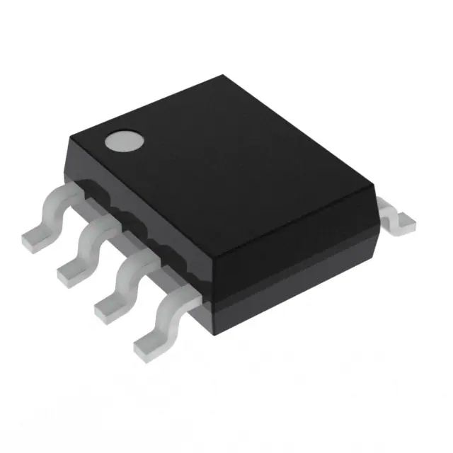

引脚分配: - SOIC-8、TSSOP-16和QFN-16封装类型,具体引脚定义根据封装类型有所不同。


参数特性: - 微功耗,可编程工作周期 - 可编程测量范围,扩展的磁场感应范围选项 - 16位磁场(XYZ)测量、16位供电电压(V)测量、14位温度(T)测量 - 支持SPI或I2C通信协议 - 支持高达2kHz的突发模式(XYZ) - 支持唤醒变化(WOC)模式 - 片上磁场校准数据,实现最大精度

功能详解: MLX90395提供多种测量模式,包括单次测量、突发模式和唤醒变化模式。

它允许在运行时通过通信协议动态配置测量参数,是一款真正的软件定义传感器。


应用信息: 适用于多媒体旋转/推杆选择器、旋钮/杆、车身控制、车门把手和门锁、后视镜位置等非接触式电位器应用。


封装信息: 提供SOIC-8、TSSOP-16和QFN-16封装选项,具体尺寸和敏感区域位置根据封装类型有所不同。
MLX90395KDC-BBA-101-SP 价格&库存

很抱歉,暂时无法提供与“MLX90395KDC-BBA-101-SP”相匹配的价格&库存,您可以联系我们找货

免费人工找货