FST15035 - FST15045
A N 4-PLCS. 1 2 3 Common Cathode C 1 L P 1.200 9 Pins eq at .150 F G J 1 2 3 D=Doubler K 1 2 3 A=Common Anode 2 3 E Dim. Inches Millimeter Minimum Maximum Minimum Maximum Notes A C E F G H J K L M N P 1.995 0.495 0.990 2.390 1.490 0.120 --0.240 0.490 0.040 0.175 0.032 2.005 0.506 1.010 2.410 1.510 0.130 0.400 0.260 0.510 .050 0.195 0.052 50.67 12.57 25.15 60.71 37.85 3.05 --6.10 12.45 1.02 4.45 0.81 50.93 12.83 25.65 61.21 38.35 3.30 10.16 6.60to Lead C L 12.95 Square 1.27 Dia 4.95 1.32
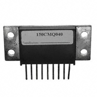
Schottky PowerMod
H
M
Notes: Baseplate: Nickel plated copper; electrically isolated Pins: Nickel plated copper Industry Part Number 150CMQ035 150CMQ040 150CMQ045
Microsemi Catalog Number FST15035* FST15040* FST15045*
Working Peak Repetitive Peak Reverse Voltage Reverse Voltage 35V 40V 45V 35V 40V 45V
Schottky Barrier Rectifier Guard Ring for Reverse Protection Low forward voltage V RRM 35 to 45 Volts Electrically isolated base Reverse Energy Tested Center tap ROHS Compliant
*Add Suffix A for Common Anode, D for Doubler
Electrical Characteristics
IF(AV) 150 Amps Average forward current per pkg IF(AV) 75 Amps Average forward current per leg IFSM Maximum surge current per leg 1000 Amps Max repetitive peak reverse current per leg I R(OV) 2 Amps VFM .60 Volts Max peak forward voltage per leg VFM .64 Volts Max peak forward voltage per leg I Max peak reverse current per leg RM 500 mA I Max peak reverse current per leg RM 2 mA C 2700 pF J Typical junction capacitance per leg TC = 72°C, Square wave, R 0JC = 0.5°C/W TC = 72°C, Square wave, R 0JC = 1.0°C/W 8.3 ms, half sine T J = 150°C f = 1 KHz, 25°C, 1µsec Square wave I FM = 75A: T J = 125°C* I FM = 75A: T J = 25°C * VRRM, T J = 125°C * VRRM, T J = 25°C VR = 5.0V, T J = 25°C
*Pulse test: Pulse width 300µsec, Duty cycle 2%
Thermal and Mechanical Characteristics
Storage temp range Operating junction temp range Max thermal resistance per leg Max thermal resistance per pkg. Typical thermal resistance (greased) Mounting torque Weight T STG TJ R OJC R OJC R OCS -55°C to 175°C -55°C to 150°C 1.0°C/W Junction to case 0.5°C/W Junction to case Case to sink 0.1°C/W 15-20 inch pounds 2.5 ounces (71 grams) typical
www.microsemi.com
January, 2010 - Rev. 2
�FST15035 - FST15045
Figure 1 Typical Forward Characteristics - Per Leg 1000 800 600 400 Junction Capacitance - pF 125 C 25 C Figure 3 Typical Junction Capacitance - Per Leg 10000 6000 4000 2000 1000 600 400 200 100 0.1
200
100 80 60 40 Instantaneous Forward Current - Amperes
0.5
1.0
5.0
10
50
100
Reverse Voltage - Volts Figure 4 Forward Current Derating - Per Leg 150 135 120 105 90 75 60 45 90 120 0 10 20 30 40 50 60 180 70 80 DC 90 100
20
10 8.0 6.0 4.0
2.0
1.0 .1 .3 .5 .7 .9 1.1 1.3 1.5 Instantaneous Forward Voltage - Volts
Maximum Allowable Case Temperature - C 125 C 100 C 75 C 25 C 0 10 20 30 40 50 Reverse Voltage - Volts
Average Forward Current - Amperes
Figure 2 Typical Reverse Characteristics - Per Leg 1000 Typical Reverse Current - mA 100
10 1.0 0.1
.01
www.microsemi.com
January, 2010 - Rev. 2
�
很抱歉,暂时无法提供与“150CMQ040”相匹配的价格&库存,您可以联系我们找货
免费人工找货