HS24380 - HS243100
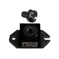
G J B Std. Polarity Base is cathode Rev. Polarity Base is anode F D Dim. Inches Millimeter Minimum Maximum Minimum Maximum Notes A B C D E F G H J K L 1.52 .725 .605 1.182 .745 .152 .525 .156 .495 .120 38.61 1.56 18.42 .775 15.37 .625 30.02 1.192 18.92 .755 3.86 .160 1/4-20 UNC-2B 13.34 .580 3.96 .160 12.57 .505 3.05 .130 39.62 19.69 15.88 30.28 19.18 4.06 14.73 4.06 12.83 3.30
240 Amp Schottky Rectifier
K H E
C
Sq. Dia.
Dia.
A
L
Microsemi Catalog Number HS24380* HS24390* HS243100*
Industry Part Number 243NQ080 MBR24080 243NQ100 MBR240100
Working Peak Repetitive Peak Reverse Voltage Reverse Voltage 80V 90V 100V 80V 90V 100V
Schottky Barrier Rectifier Guard Ring Protection 240 Amperes/80 to 100 Volts 175°C Junction Temperature Reverse Energy Tested ROHS Compliant
*Add Suffix R for Reverse Polarity
Electrical Characteristics
Average forward current Maximum surge current Maximum repetitive reverse current Max peak forward voltage Max peak forward voltage Max peak reverse current Max peak reverse current Typical junction capacitance I F(AV) I FSM I R(OV) VFM VFM I RM I RM CJ 240 Amps 3300 Amps 2 Amps 0.72 Volts 0.86 Volts 200mA 8.0mA 6400pF T C = 122°C, Square wave,R0JC =.24°C/W 8.3ms, half sine, T J = 175°C f = 1 KHZ, 25°C I FM = 240A: T J = 175°C* I FM = 240A: T J = 25°C* VRRM, T J = 125°C* VRRM, T J = 25°C VR = 5.0V, T C = 25°C
*Pulse test: Pulse width 300µsec, Duty cycle 2%
Thermal and Mechanical Characteristics
Storage temp range Operating junction temp range Max thermal resistance Typical thermal resistance (greased) Terminal Torque Mounting Base Torque Weight T STG TJ R OJC R OCS -55°C to 175°C -55°C to 175°C 0.24°C/W Junction to case 0.12°C/W Case to sink 35-40 inch pounds 20-25 inch pounds 1.1 ounces (32 grams) typical
www.microsemi.com
January, 2011 - Rev. 5
�HS24380 - HS243100
Figure 1 Typical Forward Characteristics 10,000 8000 6000 Junction Capacitance - pF 4000 Figure 3 Typical Junction Capacitance 100,000 60,000 40,000 20,000 10,000 6000 4000 2000 1000 0.1
2000
1000 800 600 400 Instantaneous Forward Current - Amperes
0.5
1.0
5.0
10
50
100
Reverse Voltage - Volts Figure 4
200
Maximum Allowable Case Temperature - C
175 C
25 C
Forward Current Derating 180 170 160 150 140 130 120 110 60 0 100 90 120 180 200 300 DC 400 500
100 80 60 40
20
10 0.2 0.4 0.6 0.8 1.0 1.2 1.4 1.6 Instantaneous Forward Voltage - Volts
Average Forward Current - Amperes
Figure 2 Typical Reverse Characteristics 1000 Typical Reverse Current - mA 100 10 125 C 1.0 0.1 .01 Maximum Power Dissipation - Watts
Figure 5 Maximum Forward Power Dissipation 350 300 250 200 150 100 50 0 0 100 200 300 400 500 Average Forward Current - Amperes 90 60 120 180 DC
175 C
75 C 25 C 0 20 40 60 80 100
Reverse Voltage - Volts
www.microsemi.com
January, 2011 - Rev. 5
�
很抱歉,暂时无法提供与“243NQ080”相匹配的价格&库存,您可以联系我们找货
免费人工找货