Schottky PowerMod
CPT50060
Baseplate A=Common Anode B
A R G
Dim. Inches Min.
A B C E F G H N Q R U V W
Millimeters Min. Max. Notes
Max.
Q
N
W Baseplate Common Cathode U C
F U
H V E
Baseplate D=Doubler Notes: Baseplate: Nickel plated copper
--3.630 0.800 0.700 0.680 --0.130 0.120 0.510 0.490 1.375 BSC --0.010 ----0.290 0.275 3.150 BSC 0.600 --0.312 0.340 0.180 0.195
--92.20 17.78 20.32 --17.28 3.30 3.05 12.45 12.95 34.92 BSC --0.25 ----6.99 7.37 80.01 BSC 15.24 --7.92 8.64 4.57 4.95
1/4-20 Dia.
Dia.
Schottky Barrier Rectifier Microsemi Industry Working Peak Catalog Number Part Number Reverse Voltage CPT50060* MBR50060CT 60V Repetitive Peak Reverse Voltage 60V Guard Ring Protection 500 Amperes/60 Volts 175°C Junction Temperature Reverse Energy Tested ROHS Compliant *Add Suffix A for Common Anode, D for Doubler
Electrical Characteristics
I F(AV) 500 Amps Average forward current per pkg I F(AV) 250 Amps Average forward current per leg I FSM 5000 Amps Maximum surge current per leg Maximum repetitive reverse current per leg I R(OV) 2 Amps VFM 0.73 Volts Max peak forward voltage per leg VFM 0.58 Volts Max peak forward voltage per leg I RM 200 mA Max peak reverse current per leg I RM Max peak reverse current per leg 8.0 mA CJ Typical junction capacitance 8800 pF TC = 132°C, Square wave, R0JC = 0.12°C/W TC = 132°C, Square wave, R0JC = 0.24°C/W 8.3ms, half sine, TJ = 175°C f = 1 KHZ, 25°C, 1µsec square wave I FM = 250A:T J = 25°C I FM = 250A:TJ = 175°C VRRM, TJ = 125°C* VRRM, TJ = 25°C VR = 5.0V,T C = 25°C
*Pulse test: Pulse width 300µsec, Duty cycle 2%
Thermal and Mechanical Characteristics
Storage temp range Operating junction temp range Max thermal resistance per leg Max thermal resistance per pkg Typical thermal resistance (greased) Terminal Torque Mounting Base Torque (outside holes) Mounting Base Torque (center hole) center hole must be torqued first Weight T STG TJ R OJC R OJC R OCS -55°C to 175°C -55°C to 175°C 0.24°C/W Junction to case 0.12°C/W Junction to case 0.08°C/W Case to sink 35-50 inch pounds 30-40 inch pounds 8-10 inch pounds 2.8 ounces (78 grams) typical
www.microsemi.com
January, 2010 - Rev. 6
�CPT50060
Figure 1 Typical Forward Characteristics - Per Leg 10,000 8000 6000 Junction Capacitance - pF 4000 Figure 3 Typical Junction Capacitance - Per Leg 100,000 60,000 40,000 20,000 10,000 6000 4000 2000 1000 0.1
2000
1000 800 600 400 Instantaneous Forward Current - Amperes
0.5
1.0
5.0
10
50
100
Reverse Voltage - Volts Figure 4
200
Maximum Allowable Case Temperature - C
175 C
25 C
Forward Current Derating - Per Leg 180 170 160 150 140 130 120 110 60 90 0 100 120 180 200 300 DC 400 500
100 80 60 40
20
10 0.2 0.4 0.6 0.8 1.0 1.2 1.4 1.6 Instantaneous Forward Voltage - Volts
Average Forward Current - Amperes
Figure 2 Typical Reverse Characteristics - Per Leg 1000 Typical Reverse Current - mA 100 10 125 C 1.0 0.1 .01 Maximum Power Dissipation - Watts
Figure 5 Maximum Forward Power Dissipation - Per Leg 210 180 150 120 90 60 30 0 0 100 200 300 400 500 Average Forward Current - Amperes 90 60 120 DC 180
175 C
75 C 25 C 0 10 20 30 40 50 60
Reverse Voltage - Volts
www.microsemi.com
January, 2010 - Rev. 6
�
很抱歉,暂时无法提供与“CPT50060”相匹配的价格&库存,您可以联系我们找货
免费人工找货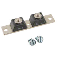


 工商网监
湘ICP备2023018690号
工商网监
湘ICP备2023018690号
