140 COMMERCE DRIVE
MONTGOMERYVILLE, PA
18936-1013
PHONE: (215) 631-9840
FAX: (215) 631-9855
MRF904
RF & MICROWAVE DISCRETE
LOW POWER TRANSISTORS
Features
•
•
•
Silicon NPN, high Frequency, To-72 packaged, Transistor
High Power Gain - GU(max): 11 dB (typ) @ f = 450 MHz
7 dB (typ) @ f = 1 GHz
Low Noise Figure
NF = 1.5 dB (typ) @ f = 450 MHz
2
•
High FT - 4 GHz (typ) @ IC = 15 mAdc
1
3
4
1. Emitter
2. Base
3. Collector
4. Case
TO-72
DESCRIPTION:
Designed primarily for use in High Gain, low noise general-purpose amplifiers.
ABSOLUTE MAXIMUM RATINGS (Tcase = 25°C)
Symbol
VCEO
Parameter
Collector-Emitter Voltage
Value
15
Unit
Vdc
VCBO
VEBO
Collector-Base Voltage
25
Vdc
Emitter-Base Voltage
3.0
Vdc
IC
Collector Current
30
mA
Total Device Dissipation @ TA = 25º C
Derate above 25º C
200
1.14
mWatts
mW/ ºC
TJMAX
Junction Temperature
200
°C
TSTORAGE
Storage Temperature
-65 to +200
°C
Thermal Data
PD
Advanced Power Technology reserves the right to change, without notice, the specifications and information contained herein
Visit our website at WWW.ADVANCEDPOWER.COM or contact our factory direct.
�MRF904
ELECTRICAL SPECIFICATIONS (Tcase = 25°C)
STATIC
(off)
Symbol
BVCEO
BVCBO
BVEBO
ICBO
Test Conditions
Value
Unit
Min.
Typ.
Max.
Collector-Emitter Breakdown Voltage
(IC = 1.0 mAdc, IB = 0)
15
-
-
Vdc
Collector-Base Breakdown Voltage
(IC= .1 mAdc, IE=0)
25
-
-
Vdc
Emitter-Base Breakdown Voltage
(IE = 0.1 mAdc, IC = 0)
3.0
-
-
-
-
50
nA
30
-
200
-
Collector Cutoff Current
(VCE = 15 Vdc, IE = 0 Vdc)
Vdc
(on)
HFE
DC Current Gain
(IC = 5.0 mAdc, VCE = 5 Vdc)
DYNAMIC
Symbol
fT
CCB
NF
Test Conditions
Value
Unit
Min.
Typ.
Max.
Current-Gain - Bandwidth Product
(IC = 15 mAdc, VCE = 10 Vdc, f = 1 GHz)
-
4.0
-
GHz
Junction Capacitance
(VCB = 10Vdc, IE=0, f=1 MHz)
-
-
1.5
pF
Noise Figure
(IC = 5.0 mAdc, VCE = 6.0 Vdc, f = 450 MHz)
-
1.5
-
dB
Advanced Power Technology reserves the right to change, without notice, the specifications and information contained herein
Visit our website at WWW.ADVANCEDPOWER.COM or contact our factory direct.
�MRF904
Functional
Symbol
Value
Test Conditions
Unit
Min.
Typ.
Max.
Maximum Unilateral Gain (1)
(IC = 5.0 mAdc, VCE = 6.0 Vdc, f = 500 MHz)
(IC = 5.0 mAdc, VCE = 6.0 Vdc, f = 1 GHz)
-
11
7
-
dB
2
|21|
Maximum Available Gain (1)
(IC = 5.0 mAdc, VCE = 6.0 Vdc, f = 500 MHz)
(IC = 5.0 mAdc, VCE = 6.0 Vdc, f = 1 GHz)
9.5
-
10.5
6.5
-
dB
MAG
Maximum Available Gain (1)
(IC = 5.0 mAdc, VCE = 6.0 Vdc, f = 500 MHz)
(IC = 5.0 mAdc, VCE = 6.0 Vdc, f = 1 GHz)
-
11
7
-
dB
GU max
S
(1) Maximum Unilateral Gain = |S21|2 / (1 - |S11|2) (1 - |S22|2)
Table 1. Common Emitter S-Parameters, @ VCE = 5 V, IC = 6 mA
f
S11
S21
S12
S22
(MHz)
|S11|
∠φ
|S21|
∠φ
|S12|
∠φ
|S22|
100
.66
-37
10.5
131
.040
71
.781
-23
200
.41
-52
7.03
111
.065
71
.597
-27
300
.31
-54
5.33
98
.093
70
.551
-26
400
.26
-59
4.00
90
.111
69
.517
-30
500
.20
-61
3.38
87
.136
71
.467
-30
600
.18
-59
3.00
81
.162
68
.455
-32
700
.16
-60
2.69
75
.186
66
.438
-36
800
.16
-66
2.30
70
.200
63
.437
-42
900
.15
-74
2.16
71
.215
65
.409
-47
1000
.15
-76
2.16
63
.243
62
.413
-48
Advanced Power Technology reserves the right to change, without notice, the specifications and information contained herein
Visit our website at WWW.ADVANCEDPOWER.COM or contact our factory direct.
∠φ
�MRF904
Advanced Power Technology reserves the right to change, without notice, the specifications and information contained herein
Visit our website at WWW.ADVANCEDPOWER.COM or contact our factory direct.
�
很抱歉,暂时无法提供与“MRF904”相匹配的价格&库存,您可以联系我们找货
免费人工找货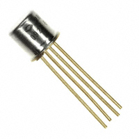


 工商网监
湘ICP备2023018690号
工商网监
湘ICP备2023018690号
