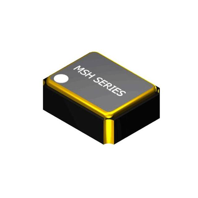
MSH302548AH-30.000MHZ-T 数据手册
MSH Series
Ο Low Profile Ceramic SMD Package
Ο Hermetically Sealed
Ο Tristate Function/Standby Option
Ο Wide Frequency Range
Electrical Specifications:
Frequency Range
1.544MHZ to 70.000MHZ
1.544MHZ to 110.000MHZ
Temperature Stability*
(See Part Number Guide for Options)
Aging (+25°C ±3°C)
±5ppm First Year
Operating Temperature Range
(See Part Number Guide for Options)
Storage Temperature Range
-55°C to +125°C
Supply Voltage (±10%)
+1.80VDC
+2.50VDC
+3.30VDC
1.544MHZ to 9.999MHZ
10mA max
12mA max
14mA max
10.000MHZ to 35.999MHZ
12mA max
14mA max
16mA max
Supply Current
36.000MHZ to 49.999MHZ
15mA max
20mA max
25mA max
50.000MHZ to 110.000MHZ
25mA max
30mA max
35mA max
Standby Current (With Stand-by Option)
100µA
VOH = 70% of Vdd min or No Connection to Enable Output
Tristate
VOL = 30% of Vdd max or grounded to Disable Output (High
Impendence)
Logic “0”
10% Vdd max
Logic “1”
90% Vdd min
Output Type
HCMOS
Symmetry (50% of waveform)
(See Part Number Guide for Options)
Rise/Fall Time (10% to 90% of Supply Voltage)
5nSEC
6nSEC
7nSEC
Load
15pF
Start-up Time
2mSec max
* Inclusive of Temperature. Load and Voltage.
Mechanical & Environmental Detail
Marking Detail
Humidity
85% RH, 85°C, 48 Hours
Hermetic Seal
Leak Rate 5 X 10⁻⁸ ATM cc/s He
Solderability
MIL-STD-202G, Method 208
Reflow
Solderability
Vibration
260°C for 10 seconds
First Line = MXX.XX (not to exceed 5
characters)
M = MMD
XX.XX = Device Frequency
(four digits including
decimal point)
MIL-STD-202G, Method 204 35G, 50 to
2000 Hz
MIL-STD-202G, Method 203 Test Cond
E, 1000G’s, ½ Sinewave
Available with Level B Screening
Second Line = SYWWL or SSYWWL
(not to exceed 6 characters)
S or SS = Internal Code
YWW = Date Code (Year/Week)
L = RoHS Compliant
Shock
MIL-STD-883
Revised M: 03/08/2021
Page 2 of 6
www.mmdcomp.com
�MSH Series
Part Number Guide
Value Added Options
Blank = No Added Options
T3 = Tape and Reel 3k pcs/reel
PLEASE CONSULT WITH MMD SALES DEPARTMENT FOR ANY OTHER PARAMETERS OR OPTIONS
Mechanical Details
Pin Connections
Pin 1 Tri-state, Standby
or No Connection
Pin 2 Case Ground
Pin 3 Output
Pin 4 Supply Voltage
Notes:
1.
2.
3.
Suggest Land Pattern
Dimension in brackets are in inches.
An External Bypass Capacitor is recommended.
Pads Plating
Base or under conductor Ni thickness; 1.3 um to 8.8 um
Final plating; Au (99.9) less than 0.5 um, 0.3 um typ
Tape & Reel Dimensions
Pitch
Tape Width
Reel DIA
Count
Pin 1 Orient
Revised M: 03/08/2021
4.00 [0.157]
8.00 [0.315]
180 [7.0]
3000
Q1
Page 3 of 6
Notes: UNLESS OTHERWISE SPECIFIED
1. Applicable Standards / Specifications
ANSI Y14.5M, Dimensions and Tolerances
EIA-481-B, 8mm through 200mm Embossed
Carrier Tapping and 8mm and 12mm
Punched Carrier Tapping of Surface Mount
Components for Automatic Handling.
2. Dimensions are in millimetres [inch].
3. Tolerances are ±0.1 [0.004] mm unless
otherwise specified.
4. Do not scale drawing.
www.mmdcomp.com
�
MSH302548AH-30.000MHZ-T 价格&库存
很抱歉,暂时无法提供与“MSH302548AH-30.000MHZ-T”相匹配的价格&库存,您可以联系我们找货
免费人工找货- 国内价格 香港价格
- 1+10.676941+1.34025
- 10+9.1701010+1.15110
- 50+8.2708750+1.03822
- 100+7.91215100+0.99319
- 500+7.14058500+0.89634
