物料型号:
- Crimp Terminals: 4809, 2759, 41572, 6459, 8088
- Crimp Housings: 2695, 6471
- PCB Connectors: 4455
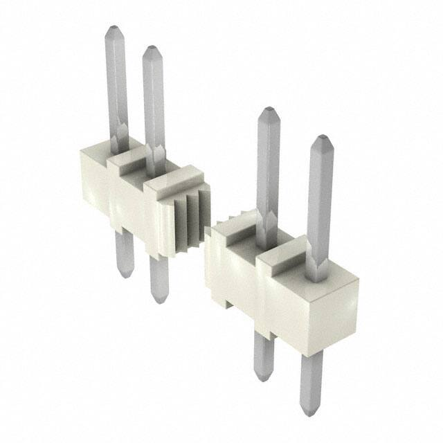
- Headers: 6410, 7395
器件简介:
文档描述了2.54毫米中心线(间距)0.64毫米方端子头,这些端子头可以与印刷电路板(PCB)连接器或使用压接技术终止的22至28 AWG线缆配合使用。
引脚分配:
文档中未明确提供引脚分配的详细信息,但提到了端子材料为黄铜或磷青铜,且有提及不同系列的端子和连接器。
参数特性:
- 电压等级:250伏特
- 电流和适用电线(取决于连接器大小、接触材料、镀层、环境温度、PCB特性等因素,实际电流等级取决于应用,应针对每个应用进行评估)
- 操作温度范围:黄铜端子为-40°C至+80°C,磷青铜端子为-40°C至+105°C
功能详解:
- 电气要求:包括接触电阻、线端接触电阻、绝缘电阻、耐电压、电容和温升测试。
- 机械要求:包括连接器插拔力、端子保持力、端子插入力、耐久性、振动、冲击和线拉力测试。
- 环境要求:包括热冲击、热老化、稳态湿热、循环湿热、焊接性和冷冲击测试。
应用信息:
文档未提供具体的应用案例,但根据端子和连接器的规格,它们适用于需要电气连接的多种应用场景。
封装信息:
文档提供了端子和连接器的尺寸、材料、镀层和标记信息,但具体的封装细节需要参考各自的图纸。


 工商网监
湘ICP备2023018690号
工商网监
湘ICP备2023018690号
