APPLICATION SPECIFICATION
154 WAY CMCHEADER
REVISION:
C
ECR/ECN INFORMATION:
EC No: UAU2012-1574
DATE: 06/15/2012
DOCUMENT NUMBER:
AS-34763-001
TITLE:
SHEET No.
154 WAY CMC HEADER
1 of 16
CREATED / REVISED BY:
CHECKED BY:
APPROVED BY:
Brian Zelinski
Dave Krawczyk
Ron Bauman
TEMPLATE FILENAME: APPLICATION_SPEC[SIZE_A](V.1).DOC
�APPLICATION SPECIFICATION
154 WAY CMC HEADER
Table of Contents
� 154 way CMC Product Introduction
� 154 way CMCProduct Summary
� 154way CMCHeader Overview
� 154 way CMC CAD Model Reference
� 154 way CMC Header Product Identification
� 154 way CMC Header Packaging
� 154 way CMC Header-to-PCB Assembly Instructions
� 154 way CMC Header-to-PCB Assembly Tooling
� 154 way Header PCB Side Probing
� 154 way Harness Side Probing
� 53 wayand 48 way CMC Connector Mating &Unmating
REVISION:
C
ECR/ECN INFORMATION:
EC No: UAU2012-1574
DATE: 06/15/2012
DOCUMENT NUMBER:
AS-34763-001
TITLE:
SHEET No.
154 WAY CMC HEADER
2 of 16
CREATED / REVISED BY:
CHECKED BY:
APPROVED BY:
Brian Zelinski
Dave Krawczyk
Ron Bauman
TEMPLATE FILENAME: APPLICATION_SPEC[SIZE_A](V.1).DOC
�APPLICATION SPECIFICATION
154 WAY CMC HEADER
PRODUCT INTRODUCTION
154 Way CMCHeader
•
Terminal Header Blades
- The three-bay CMC Header assembly consisting of 154 blade contacts.
- The blade contact interfaces are 0.6 mm, 1.50 mm and 2.80 mm.
- This header assembly is intended to be attached to a printed circuit board by a press-fit compliant
contact.
Molex 53 / 48-wayCMC Connector System:
•
•
•
This is a sealed connection system.
53Way CMC Harness Connector – 64321xxxx / 98995xxxx
48Way CMC Harness Connector – 64320xxxx / 98993xxxx
•
Terminals used in the CMC connector system:
- CP0.6 Sn Receptacle Terminal – 6432210x9 – 0.35mm2 - 0.75mm2 wire
- CP0.6 Au Receptacle Terminal – 6432212x9 – 0.35mm2 - 0.75mm2 wire
- CP1.5 Sn Receptacle Terminal – 6432310x9 – 0.5mm2 - 2.0mm2 wire
- CP1.5 Au Receptacle Terminal – 643231x19 – 0.5mm2 - 2.0mm2 wire
- CP2.8 Sn Receptacle Terminal – 6432410x9 – 2.5mm2 - 5.0mm2 wire
Applicable Documents and Specifications
•
•
•
•
•
•
•
•
•
•
REVISION:
C
154way CMC Header Assembly – SD-34763-001
53way CMC Harness Connector – SD-64321-001
48way CMC Harness Connector – SD-64320-001
CP0.6 Sn Receptacle Terminal – SD-64322-001
CP1.5 Sn Receptacle Terminal – SD-64323-001
CP2.8 Sn Receptacle Terminal – SD-64324-001
EON 0.64 – SD-34481-012
EON 1.5 / 2.8 – SD-78007-012
32 and 48 CMC connector User Manual – AS-64319-001
53 way CMC connector User Manual –AS-64321-001
ECR/ECN INFORMATION:
EC No: UAU2012-1574
DATE: 06/15/2012
DOCUMENT NUMBER:
AS-34763-001
TITLE:
SHEET No.
154 WAY CMC HEADER
3 of 16
CREATED / REVISED BY:
CHECKED BY:
APPROVED BY:
Brian Zelinski
Dave Krawczyk
Ron Bauman
TEMPLATE FILENAME: APPLICATION_SPEC[SIZE_A](V.1).DOC
�APPLICATION SPECIFICATION
154 WAY CMC HEADER
154 WAY CMC HEADER PRODUCT SUMMARY
HIGHLIGHTS:
•
•
•
Connector is sealed.
Connector provides temporary retention to the header before the Lever Arm is activated.
Lever Arm remains in locked position until the harness connector is in pre-lock position on the
header/controller.
Compliant Interface
• EON on 0.64 blades per SD-34481-012
• EON on 1.50 & 2.80 blades per SD-78007-012
• PCB specification
- PCB in accordance with IEC 60352-5
- Material FR4 min. TG 130
- Single layer thickness larger than 0.8 mm
- Total thickness of PCB from 1.5 to 2.4 mm in accordance with the IEC 60326-3. If other
- PCB thickness required, Molex Engineering to approve.
Temperature
Operating: -40°C to +105°C
Current
• The maximum test current capability per USCAR-2 rev5:
- 0.6 blade mated to a CP0.6 Sn or Au plated receptacle crimped to 0.75mm2 wire – 8.0 A
- 1.50 blade mated to a CP1.5 Snor Au plated receptacle crimped to 2.0mm2 wire – 10.5 A
- 2.80 blade (single strap) mated to a CP2.8 Sn plated receptacle crimped to 5.0mm2 wire – 13.5 A
- 2.80 blade (dual strap) mated to a CP2.8 Sn plated receptacle crimped to 5.0mm2 wire – 17.0 A
Voltage
250VAC per PS-64321-001 and PS-64319-001
For product ordering information, please contact your Molex Inside Sales Representative at
(800)786-6539.
For electronic copies and future updates of this document, and the Connector Reference
Manual, refer to the Molex Website at http://www.molex.com/
REVISION:
C
ECR/ECN INFORMATION:
EC No: UAU2012-1574
DATE: 06/15/2012
DOCUMENT NUMBER:
AS-34763-001
TITLE:
SHEET No.
154 WAY CMC HEADER
4 of 16
CREATED / REVISED BY:
CHECKED BY:
APPROVED BY:
Brian Zelinski
Dave Krawczyk
Ron Bauman
TEMPLATE FILENAME: APPLICATION_SPEC[SIZE_A](V.1).DOC
�APPLICATION SPECIFICATION
154 WAY CMC HEADER
THIS PROCEDURE APPLIES TO ALL PART NUMBERS IN THE 34763-00xxSERIES
REVISION:
C
ECR/ECN INFORMATION:
EC No: UAU2012-1574
DATE: 06/15/2012
DOCUMENT NUMBER:
AS-34763-001
TITLE:
SHEET No.
154 WAY CMC HEADER
5 of 16
CREATED / REVISED BY:
CHECKED BY:
APPROVED BY:
Brian Zelinski
Dave Krawczyk
Ron Bauman
TEMPLATE FILENAME: APPLICATION_SPEC[SIZE_A](V.1).DOC
�APPLICATION SPECIFICATION
154 WAY CMC HEADER
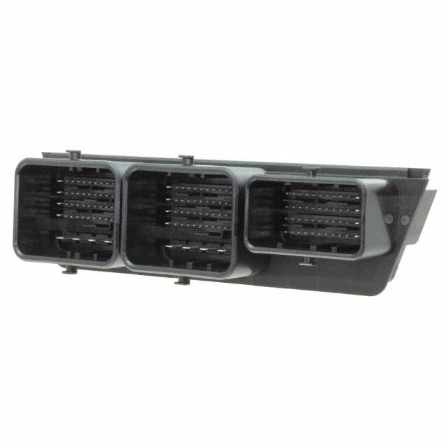
HEADER OVERVIEW
PAP – “Pin Alignment Plate”
2.8 Blade
0.6 Blade
1.5 Blade
53 Way Pocket
53 Way Pocket
48 Way Pocket
REVISION:
C
ECR/ECN INFORMATION:
EC No: UAU2012-1574
DATE: 06/15/2012
DOCUMENT NUMBER:
AS-34763-001
TITLE:
SHEET No.
154 WAY CMC HEADER
6 of 16
CREATED / REVISED BY:
CHECKED BY:
APPROVED BY:
Brian Zelinski
Dave Krawczyk
Ron Bauman
TEMPLATE FILENAME: APPLICATION_SPEC[SIZE_A](V.1).DOC
�APPLICATION SPECIFICATION
154 WAY CMC HEADER
154 way CMC CAD MODEL REFERENCE
CMC CADmodel reference for 154 way CMC header Top Plate, PCB and Casting. All CADmodels are to be
used as REFERENCE ONLY. ALL FINAL DESIGNS FROM ALL CAD MODELS ARE THE
RESPONSIBILITY OF THE CUSTOMER.
Top Plate CM-34763-903
PCB CM-34763-901
154 way CMC Header
Casting CM-34763-902
Holding Fixture CM-34763-904
REVISION:
C
ECR/ECN INFORMATION:
EC No: UAU2012-1574
DATE: 06/15/2012
DOCUMENT NUMBER:
AS-34763-001
TITLE:
SHEET No.
154 WAY CMC HEADER
7 of 16
CREATED / REVISED BY:
CHECKED BY:
APPROVED BY:
Brian Zelinski
Dave Krawczyk
Ron Bauman
TEMPLATE FILENAME: APPLICATION_SPEC[SIZE_A](V.1).DOC
�APPLICATION SPECIFICATION
154 WAY CMC HEADER
154 WAY CMC HEADER PRODUCT IDENTIFICATION
•
All parts are laser marked with:
Area (A)
- Marking and Reading Standard: Data Matrix (ECC200)
- Information Encoded:
• CC – Configuration Number Per Configuration / BOM Table
• YY – Year
• DDD – Day of year
• SSSS – Incremental Serial Number
• MXN – Supplier Designation/Manufacturing Location
Area (B)
- Human readable code (HRC)
- Information Encoded:
• 9 Digit Molex Material Number
• 4 Digit Julian Manufacturing Date Stamp DDDY
• 4 Digit Incremental Serial Number
• 1 Digit Molex Manufacturing Code
Area (A)
Area (B)
XXXXXXXXX
XXXX XXXXX X
REVISION:
C
ECR/ECN INFORMATION:
EC No: UAU2012-1574
DATE: 06/15/2012
DOCUMENT NUMBER:
AS-34763-001
TITLE:
SHEET No.
154 WAY CMC HEADER
8 of 16
CREATED / REVISED BY:
CHECKED BY:
APPROVED BY:
Brian Zelinski
Dave Krawczyk
Ron Bauman
TEMPLATE FILENAME: APPLICATION_SPEC[SIZE_A](V.1).DOC
�APPLICATION SPECIFICATION
154 WAY CMC HEADER
154 WAY CMC HEADER PACKAGING
Molex recommends moving the cell pack box directly to the assembly line, this will insure against damage.
Headers should remain in the Molex cell pack until assembled.
Parts as received in cell pack
PAP is not in pre-lock position scrap header
PAP is shipped in pre-lock position
All headers shipped in cell packed boxes
REVISION:
C
ECR/ECN INFORMATION:
EC No: UAU2012-1574
DATE: 06/15/2012
DOCUMENT NUMBER:
AS-34763-001
TITLE:
SHEET No.
154 WAY CMC HEADER
9 of 16
CREATED / REVISED BY:
CHECKED BY:
APPROVED BY:
Brian Zelinski
Dave Krawczyk
Ron Bauman
TEMPLATE FILENAME: APPLICATION_SPEC[SIZE_A](V.1).DOC
�APPLICATION SPECIFICATION
154 WAY CMC HEADER
154 WAY CMC HEADER-TO-PCB ASSEMBLY INSTRUCTIONS
(Recommended header mounting strategies and mounting steps: areas where
to apply force to seat header to the PCB)
Header Fixture CM-34763-904
PCB
Step 1 - Line up
CMC to Fixture
REVISION:
C
ECR/ECN INFORMATION:
EC No: UAU2012-1574
DATE: 06/15/2012
DOCUMENT NUMBER:
AS-34763-001
Step 2 – Slide CMC
Header on Fixture
Step 3 – Place PCB
on CMC Header
TITLE:
SHEET No.
154 WAY CMC HEADER
10 of 16
CREATED / REVISED BY:
CHECKED BY:
APPROVED BY:
Brian Zelinski
Dave Krawczyk
Ron Bauman
TEMPLATE FILENAME: APPLICATION_SPEC[SIZE_A](V.1).DOC
�APPLICATION SPECIFICATION
Step 4 – Press
down on the PCB in
these locations
ONLY to mate the
PCB to the CMC
header
DIM (A)
DIM (A) – see EON Sales Drawings
NOTE: DO NOT APPLYANY PRESSURE TO PINS. PRESSURE PLACED ON THE
HEADER PINS MAY DAMAGE THE ASSEMBLY.
REVISION:
C
ECR/ECN INFORMATION:
EC No: UAU2012-1574
DATE: 06/15/2012
DOCUMENT NUMBER:
AS-34763-001
TITLE:
SHEET No.
154 WAY CMC HEADER
11 of 16
CREATED / REVISED BY:
CHECKED BY:
APPROVED BY:
Brian Zelinski
Dave Krawczyk
Ron Bauman
TEMPLATE FILENAME: APPLICATION_SPEC[SIZE_A](V.1).DOC
�APPLICATION SPECIFICATION
154 WAY CMC HEADER
154 WAY CMC HEADER-TO-PCB ASSEMBLY TOOLING
Molex also offers a low volume PCB to header assembly tool for the 154way CMC Header.
For product ordering information, please contact your Molex Inside Sales Representative at (800)786-6539.
Reference- 154 Way PCB Insertion Tool Operation Manual Order No. 62203-0500
REVISION:
C
ECR/ECN INFORMATION:
EC No: UAU2012-1574
DATE: 06/15/2012
DOCUMENT NUMBER:
AS-34763-001
TITLE:
SHEET No.
154 WAY CMC HEADER
12 of 16
CREATED / REVISED BY:
CHECKED BY:
APPROVED BY:
Brian Zelinski
Dave Krawczyk
Ron Bauman
TEMPLATE FILENAME: APPLICATION_SPEC[SIZE_A](V.1).DOC
�APPLICATION SPECIFICATION
154 WAY CMC HEADER
154 WAY HEADER PCB SIDE PROBING
Electrical continuity check list
Probe pin recommendations:
1. When testing the header for continuity it is imperative that you do not damage the pins.
2. Pogo pins should be checked for damage or sticking several times a shift. This should assure containment
if an issue is found.
3. First a visual inspection of all the pins for damage should be performed.
4. Next a testing block should be used to depress all the pogo pins up into the barrel. If there is a bent or
sticking pin, it should remain stuck in the barrel of the pogo pin. A damaged or stuck pin should be replaced
before any additional testing is performed.
Probing damage can occur:
1. If a sharp ended probe is used to contact the end terminal it may damage the pin tip and plating and
increase contact resistance and mate force.
2. If a probe is inserted into the header on an angle or off center it may damage the pins, and or the
connector.
154 way CMCPCB SIDELAYOUT
(see SD-34763-001)
REVISION:
C
ECR/ECN INFORMATION:
EC No: UAU2012-1574
DATE: 06/15/2012
DOCUMENT NUMBER:
AS-34763-001
TITLE:
SHEET No.
154 WAY CMC HEADER
13 of 16
CREATED / REVISED BY:
CHECKED BY:
APPROVED BY:
Brian Zelinski
Dave Krawczyk
Ron Bauman
TEMPLATE FILENAME: APPLICATION_SPEC[SIZE_A](V.1).DOC
�APPLICATION SPECIFICATION
154 WAY CMC HEADER
154 WAY HEADER HARNESS SIDEPROBING
Electrical continuity check list
Probe pin recommendations:
5. When testing the header for continuity it is imperative that you do not damage the pins.
6. Pogo pins should be checked for damage or sticking several times a shift. This should assure containment
if an issue is found.
7. First a visual inspection of all the pins for damage should be performed.
8. Next a testing block should be used to depress all the pogo pins up into the barrel. If there is a bent or
sticking pin, it should remain stuck in the barrel of the pogo pin. A damaged or stuck pin should be replaced
before any additional testing is performed.
Probing damage can occur:
3. If a sharp ended probe is used to contact the end terminal it may damage the pin tip and plating and
increase contact resistance and mate force.
4. If a probe is inserted into the header on an angle or off center it may damage the pins, and or the
connector.
154 way CMC HARNESS SIDELAYOUT
(see SD-34763-001)
REVISION:
C
ECR/ECN INFORMATION:
EC No: UAU2012-1574
DATE: 06/15/2012
DOCUMENT NUMBER:
AS-34763-001
TITLE:
SHEET No.
154 WAY CMC HEADER
14 of 16
CREATED / REVISED BY:
CHECKED BY:
APPROVED BY:
Brian Zelinski
Dave Krawczyk
Ron Bauman
TEMPLATE FILENAME: APPLICATION_SPEC[SIZE_A](V.1).DOC
�APPLICATION SPECIFICATION
154 WAY CMC HEADER
53 WAY AND 48WAY CMC CONNECTOR MATING& UNMATING
The color marking on the cam Posts on the CMC header corresponds to the color of the front face of the connector
that is to be mated to the correct bay.
Mating the connector:
1. The lever must be in open (delivery) position before mating operation.
2. Insert the connector till it stops in the header pocket.
3. Rotate the lever and lock it on the wire cap.
Color marking on header
The lever must be in open (delivery)
position before mating operation.
- Insert the connector till it stops in the header pocket.
- Rotate the lever till the stop and the locking on the cover
REVISION:
C
ECR/ECN INFORMATION:
EC No: UAU2012-1574
DATE: 06/15/2012
DOCUMENT NUMBER:
AS-34763-001
TITLE:
SHEET No.
154 WAY CMC HEADER
15 of 16
CREATED / REVISED BY:
CHECKED BY:
APPROVED BY:
Brian Zelinski
Dave Krawczyk
Ron Bauman
TEMPLATE FILENAME: APPLICATION_SPEC[SIZE_A](V.1).DOC
�APPLICATION SPECIFICATION
Locking latch (on the wire cap / wire dress cover)
Unmating the connector:
1. Press on the locking located on the wire cap and rotate the lever until its locking on the female housing
2. Remove the female connector from the header
REVISION:
C
ECR/ECN INFORMATION:
EC No: UAU2012-1574
DATE: 06/15/2012
DOCUMENT NUMBER:
AS-34763-001
TITLE:
SHEET No.
154 WAY CMC HEADER
16 of 16
CREATED / REVISED BY:
CHECKED BY:
APPROVED BY:
Brian Zelinski
Dave Krawczyk
Ron Bauman
TEMPLATE FILENAME: APPLICATION_SPEC[SIZE_A](V.1).DOC
�
很抱歉,暂时无法提供与“0347630001”相匹配的价格&库存,您可以联系我们找货
免费人工找货- 国内价格 香港价格
- 1024+217.136661024+28.14505