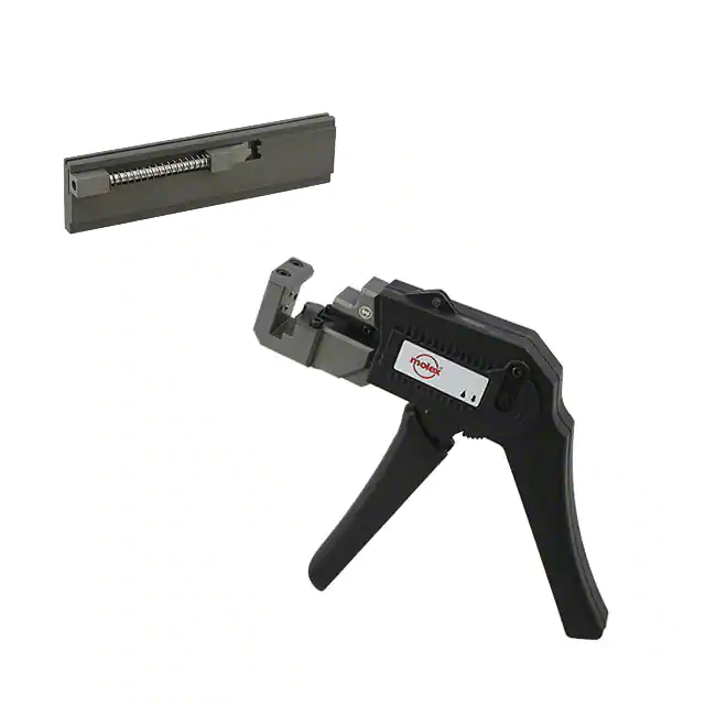
IDT Hand Tool Module
IDT
Mini Mi II™ System
Hand Tool
Application Tooling
Specification Sheet
Order No. 62100-9800
FEATURES
�
�
%
%
Terminates wire directly into the receptacle housing assembly
Accommodate 2 to 20 circuit connectors
A full cycle ratchet ensures complete terminations
This tool is designed for prototype or low volume work only and is not intended for production
SCOPE
Products: 1.25mm (.049") Pitch Mini Mi II™ System Wire-to-Board Insulation Displacement Receptacle Housing
assemblies. Series 51336 and 54596 (2 to 20-circuits)
Applicable wire: UL10272 AWG 26/28 discrete wire (Insulation O.D 0.8-0.9mm)
Product List
The following is a partial list of the product order numbers that this tool is designed to run. Updates to this list are
available on www.molex.com.
Connector Series No.
51336
54596
Doc No: ATS-621009800
Revision: B
51336-0210
51336-0810
51336-1410
51336-2010
54596-0210
54596-0410
54596-0610
54596-0810
54596-1010
54596-1210
54596-1410
54596-1610
54596-1810
54596-2010
Connector Order No.
51336-0310 51336-0410 51336-0510 51336-0610 51336-0710
51336-0910 51336-1010 51336-1110 51336-1210 51336-1310
51336-1510 51336-1610 51336-1710 51336-1810 51336-1910
54596-0212
54596-0412
54596-0612
54596-0812
54596-1012
54596-1212
54596-1412
54596-1612
54596-1812
54596-2012
Release Date: 07-07-10
Revision Date: 09-20-10
54596-0213
54596-0413
54596-0613
54596-0813
54596-1013
54596-1213
54596-1413
54596-1613
54596-1813
54596-2013
54596-0310
54596-0510
54596-0710
54596-0910
54596-1110
54596-1310
54596-1510
54596-1710
54596-1910
UNCONTROLLED COPY
54596-0312
54596-0512
54596-0712
54596-0912
54596-1112
54596-1312
54596-1512
54596-1712
54596-1912
54596-0313
54596-0513
54596-0713
54596-0913
54596-1113
54596-1313
54596-1513
54596-1713
54596-1913
Page 1 of 7
�IDT Hand Tool Module
INDEX LOCATORS
OPERATION
Open the hand tool by squeezing
the handles together. At the end
of the closing stroke, the ratchet
mechanism will and the handle will
spring open.
CONNECTOR
SLIDE
SPRING
PLUNGER
LOCK
1. Pull back on the spring
NEST
plunger lock on the connector
CONNECTOR
slide and hold it in place.
2. Place the proper connector
into the connector slide; the
flat side of the connector
HANDLES
should be against the slide,
OPEN
Figure 1
and the slots should be facing
up. See Figure 1.
3. Release the spring plunger
lock. The spring plunger lock will extend and hold the connector.
4. Insert the connector slide into the track of the hand tool by firmly pushing it over the index locators until an
audible “click” is heard. This will be the first position for the first wire. Connectors can be loaded with the
connector slide already installed in the tool.
WIRE PUSHED INTO THE
CONNECTOR
WIRE
CONNECTOR
IN PLACE
CONNECTOR
IN PLACE
CONNECTOR
SLIDE
TERMINATION PUNCH
Figure 2
WIRE SLOT
Figure 3
5. Place the first wire into the wire slot until it stops. See Figure 2.
6. While holding the wire in place, squeeze the handles together, the termination punch will terminate the wire
into the connector. See figure 3.
7. Continue squeezing the handles together until the ratchet releases.
8. Open the tool handles slowly.
Doc No: ATS-621009800
Revision: B
Release Date: 07-07-10
Revision Date: 09-20-10
UNCONTROLLED COPY
Page 2 of 7
�IDT Hand Tool Module
Note: The full cycle ratchet action will not release the tool until it has been fully closed.
Note: If something jams, the ratchet mechanism can be released by pushing upward on the ratchet pawl at the
base of the trigger. See Figure 5.
9.
10.
11.
12.
13.
Index to the next position by pushing the connector slide over until it stops or “clicks” into position.
Repeat steps 5, 6, and 7 until all wires are terminated.
Push the connector slide all the way to the left.
Pull back on the spring plunger lock on the connector slide and hold down.
Remove the completed connector assembly from the slide.
COMPLETE
CONNECTOR
ASSEMBLY
CONNECTOR
SLIDE
HANDLES OPEN
LAST WIRE
TERMINATED
Figure 4
Doc No: ATS-621009800
Revision: B
Release Date: 07-07-10
Revision Date: 09-20-10
UNCONTROLLED COPY
Page 3 of 7
�IDT Hand Tool Module
CAUTION: Molex specifications are valid only when used with Molex connectors and tooling.
Doc No: ATS-621009800
Revision: B
Release Date: 07-07-10
Revision Date: 09-20-10
UNCONTROLLED COPY
Page 4 of 7
�IDT Hand Tool Module
Maintenance
It is recommended that each operator of the tool be made aware of, and responsible for, the following maintenance
steps:
1. Remove the plastic handles from the metal tool frame by removing the screws and remove dust, moisture, and
other contaminants with a clean brush, or soft, lint free cloth.
2. Do not use any abrasive materials that could damage the tool.
3. Make certain all pins; pivot points and bearing surfaces are protected with a thin coat of high quality machine
oil. Do not oil excessively. The tool was engineered for durability, but like any fine piece of equipment, it needs
cleaning and lubrication for a maximum service life of trouble free terminating. Light oil used at the pivot points
every 5,000 terminations or 3 months, will significantly enhance the tool life.
4. Wipe excess oil from hand tool, particularly from the terminating area.
5. When tool is not in use, keep the handles closed to prevent objects from becoming lodged in the termination
punch and store the tool in a clean, dry area.
Miscrimps or Jams
Should this tool ever become stuck or jammed in a
partially closed position, Do Not force the handles
open or closed. The tool will open easily by pressing
the ratchet release lever up. See Figure 5.
How to Adjust Tool Preload
RATCHET
RELEASE LEVER
It may be necessary over the life of the tool to adjust
tool handle preload force. Listed below are the steps
required to adjust the termination force of the hand
tool to obtain proper conditions:
NUMBERED ADJUSTMENT
WHEEL
Figure 5
REMOVE THE LOCKING 2mm SCREW
TURN WITH A SMALL
SCREW DRIVER
Figure 6
TURN CLOCKWISE (CW) OR
COUNTER CLOCKWISE (CCW)
TO ADJUST THE PRE-LOAD
Doc No: ATS-621009800
Revision: B
Release Date: 07-07-10
Revision Date: 09-20-10
UNCONTROLLED COPY
Page 5 of 7
�IDT Hand Tool Module
1. Remove the 2mm locking screw from the numbered adjusting wheel using a screw driver. See Figure 6.
2. Using the same screw driver turn the adjustment wheel to the next highest number.
Note: The uneven numbers are in clockwise (CW) direction and the even numbers are counter clockwise
(CCW).
3. Example: If the preload is set at number 5, then to increase the preload, turn the adjustment wheel until the 6th
position is located over the 2mm locking screw tapped hole. If it is necessary to move to the 7th position, then
the adjustment wheel should be turned counter clockwise (CCW) until the 7th position is over the 2mm locking
screw tapped hole.
4. Replace the 2mm locking screw, aligning the nearest notch in the setting wheel to locking screw.
5. Check for proper termination depth after the tool handle preload force is adjusted. Repeat these steps until
the desired result is obtained.
Warranty
This tool is for terminating individual wires into insulation displacement connectors only. This tool is made of the
best quality materials. All vital components are long life tested. All tools are warranted to be free of manufacturing
defects for a period of 30 days. Should such a defect occur, we will repair or exchange the tool, free of charge.
This repair or exchange will not be applicable to altered, misused, or damaged tools. This tool is designed for
hand use only. Any clamping, fixturing, or use of handle extensions voids this warranty.
CAUTION: Molex specifications are valid only when used with Molex connectors and tooling.
CAUTIONS:
1. Manually powered hand tools are intended for low volume, prototyping, or field repair. This tool is NOT
intended for production use. Repetitive use of this tool should be avoided.
2. Insulated handles are not protection against electrical shock.
3. Wear eye protection at all times.
4. Use only the Molex connectors and wires specified for this tool.
Doc No: ATS-621009800
Revision: B
Release Date: 07-07-10
Revision Date: 09-20-10
UNCONTROLLED COPY
Page 6 of 7
�IDT Hand Tool Module
PARTS LIST
Item
1
2
3
4
5
Order No
Description
Quantity
63819-4800 Hand Crimp Tool 1 (Figure 4)
11-11-0320
Spring (Ratchet)
1
63600-0479
Spring (Main)
1
69008-0972
Adjuster Wheel
1
62100-9801 Termination Punch
1
3
4
1
5
2
Figure 4
http://www.molex.com
Doc No: ATS-621009800
Revision: B
Release Date: 07-07-10
Revision Date: 09-20-10
UNCONTROLLED COPY
Page 7 of 7
�
很抱歉,暂时无法提供与“0621009800”相匹配的价格&库存,您可以联系我们找货
免费人工找货- 国内价格 香港价格
- 1+6051.566491+785.59171