VHDM and VHDM-HSD*
*VHDM and VHDM HSD are Trademark of Teradyne, Inc
VHDM® AND VHDM-HSD™
INSTALLATION and REPAIR TOOLING
Operation Manual
Order No. 62201-0999
� Description
� Operation
� Maintenance
Doc. No: TM-622010999
Revision: H
Release Date: 08-10-99
Revision Date: 03-15-10
UNCONTROLLED COPY
Page 1 of 23
�VHDM and VHDM-HSD*
*VHDM and VHDM HSD are Trademark of Teradyne, Inc
WARNING
NEVER
OPERATE, SERVICE, INSTALL, OR ADJUST THIS TOOL WITHOUT
PROPER INSTRUCTION AND WITHOUT FIRST READING AND
UNDERSTANDING THE INSTRUCTIONS IN THIS MANUAL.
WORK SAFELY AT ALL TIMES
For Service, Contact Your
Local Molex Sales Office
Molex Application Tooling Group
2200 Wellington Court
Lisle, Illinois 60532
Tel: 630-969-4550
Fax: 630-505-0049
Visit our Web site at http://www.molex.com
Doc. No: TM-622010999
Revision: H
Release Date: 08-10-99
Revision Date: 03-15-10
UNCONTROLLED COPY
Page 2 of 23
�VHDM and VHDM-HSD*
*VHDM and VHDM HSD are Trademark of Teradyne, Inc
Table of Contents
SECTION
1
General Description and Available Presses
2
Installation and Operation
3
Maintenance, Spare Parts, Perishable Parts and Problem Checklist
4
Available tooling
5
Glossary of Terms
APPENDIX
A
Parts Lists and Drawings for Standard Tools
B
Instruction Sheets for Repair Tools
C
Parts Lists and Drawings for Customer Specials
D
Product Specifications
Doc. No: TM-622010999
Revision: H
Release Date: 08-10-99
Revision Date: 03-15-10
UNCONTROLLED COPY
Page 3 of 23
�VHDM and VHDM-HSD*
*VHDM and VHDM HSD are Trademark of Teradyne, Inc
Section 1
General Description and Available Presses
1.1
Description
1.2
Features
1.3
Technical Specifications
1.4
Delivery Check
1.5
Tools
1.6
Press Requirements
Doc. No: TM-622010999
Revision: H
Release Date: 08-10-99
Revision Date: 03-15-10
UNCONTROLLED COPY
Page 4 of 23
�VHDM and VHDM-HSD*
*VHDM and VHDM HSD are Trademark of Teradyne, Inc
General description
Rate
90 connectors pressed in (one at a time) per hour
depending on operator skill.
1.1 Description
This manual covers the tooling available to press Molex
VHDM and HSD Back plane Power Modules, Back
plane Connectors, and Daughter Card Modules into
printed circuit boards. Repair tools and custom tools are
also covered. The tooling is designed to go into a flat
platen press. Operation is simple: Position a printed
circuit board on the customer supplied support. Then
manually insert a connector(s) into the pc board.
Position the loading head into the connector. Actuate
the press to press the connector pins into the board.
1.4 Delivery Check
Carefully remove the tooling from its shipping container
and check to be sure what was received matches the
purchase order and no damage has occurred.
1.5 Tools
A metric hex wrench set will be required to assemble or
disassemble tooling mounted in rails.
1.2 Features
The press-in tooling is designed so that one module will
press in one connector, or several modules can be
mounted in a tool holder and be used to press in any
combination of connectors in one operation. See
Section 1.8 (Ordering Instructions) for details.
Figure 1-3
62202-6400 15-Ton Press
Molex Presses
Molex offers two (2) presses that are suitable for this
application. (See also Figure 1-1 and 1-2. They are:
62201-3800
62200-6400
8-ton Pneumatic Flat Platen Press
15-ton Electric Flat Platen Press
Figure 1-1
62201-3800 8-TON PRESS
1.3 Technical Specifications
Dimensions and Weight
The dimensions and weight depend on the tooling used
and the size of the pc board support. The dimensions
and weights of the various tooling components are given
in the assembly drawings in Appendixes A, B, and C.
Doc. No: TM-622010999
Revision: H
Release Date: 08-10-99
Revision Date: 03-15-10
UNCONTROLLED COPY
Page 5 of 23
�VHDM and VHDM-HSD*
*VHDM and VHDM HSD are Trademark of Teradyne, Inc
1.6 Press Requirements
This tooling is designed to fit in a flat platen (or flat rock)
press, capable of 66N (15 lbs) of force per pin.
Letter Description
See Figure1-3.
A Upper Platen
B Opening
C Throat
A
Dimension (min)
51mm by 102mm by 25.4mm
(2” by 4” by 1”)
89mm (3.5”)
50mm (6”)
B
C
Figure 1-3
PRESS THROAT DIMENSIONS
Doc. No: TM-622010999
Revision: H
Release Date: 08-10-99
Revision Date: 03-15-10
UNCONTROLLED COPY
Page 6 of 23
�*VHDM and VHDM HSD are Trademark of Teradyne Inc.
VHDM AND VHDM-HSD
Section 2
Installation and Operation
2.1
Backup for printed circuit boards
2.2
Press stroke adjustment
2.3
Installation
2.4
Operation
Doc. No: ATS-622010999
Revision: F
Release Date: 08-10-99
Revision Date: 05-01-08
UNCONTROLLED COPY
Page 7 of 23
�VHDM and VHDM-HSD*
*VHDM and VHDM HSD are Trademark of Teradyne, Inc
2.1 Printed Circuit Board Support
The HSD / VHDM tooling requires up to 15 lb per pin of
force to press the connectors into the printed circuit
boards. Therefore, a backup or support is required to
prevent damage to the printed circuit boards. The
support fixture should have clearance for the connector
terminals when they protrude through the underside of
the printed circuit board. It is also recommended that
the support fixture have locating pins. Due to the
custom nature of each application, Molex does not
supply support and locating fixtures, the customer
normally supplies them.
10. Press the connector into the p.c. board and observe
for any deflection of the board when the ram is at
the bottom of its stroke.
2.2 Press Stroke Adjustment
Most presses have some means of adjusting the stroke;
please refer to the appropriate manual (for the press
being used) for press stroke adjustments. The stroke
should be adjusted so that when the press ram stops in
the down position, the bottom of the connector is flush to
.155mm (.006 in.) above the surface of the printed circuit
board.
See Figure 2-1.
The following is one simple way of making a printed
circuit board support and locating fixture:
1. Locate a suitable piece of material for the backup. It
should be approximately 3/4 inch thick and same
size or a little larger than the printed circuit board to
be used. While aluminum could be used, a rigid
nonconductive material such as a phenolic is
preferred. (A stack of scrap p.c. boards of suitable
size could be fastened together and used.)
2. Obtain a scrap p.c. board like the ones to be
assembled. Attach this board to the material from
step 1.
3. Using an oversize drill bit, drill through each hole
where a pin from the connector will go. Drill deep
enough into the lower material to be certain the pins
do not bottom out when inserted (at least 5mm
[0.20in] deep).
4. Locate two (2) holes on the p.c. board to use as
locating points. Drill for and mount suitably sized
dowel pins in these two locations on the support
fixture.
5. Clear out the support for any components mounted
on the underside of the printed circuit board.
6 Place a p.c. board on top of the support, located by
the two pins, and check that the holes for the
connector pins are aligned.
7. Pre-insert a connector in the p.c. board in the
correct position.
8. Insert the press-in tool of proper size into the
connector.
9. Place the support with p.c. board under the press
ram.
Doc. No: TM-622010999
Revision: H
Release Date: 08-10-99
Revision Date: 03-15-10
.155mm
(.006”)
Maximum
Figure 2-1
MAXIMUM CLEARANCE WHEN
CONNECTOR FULLY SEATED
2.3 Installation
The only installation required is when you need to install
insertion modules into a tooling holder. To do this, use
the following procedure:
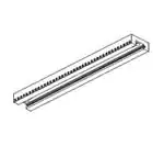
KEYWAY
Figure 2-2
TOOLING HOLDER
M3 SET SCREW
1. Along the lower edge of the tooling holder is a row of
M3 set screws, back these out so that they do not
protrude into the inside of the holder. See Figure 22.
2. Slide the insertion modules into the tooling holder in
the proper order. See Figure 2-3. The modules are
keyed so that they cannot be put in backwards.
UNCONTROLLED COPY
Page 8 of 23
�VHDM and VHDM-HSD*
*VHDM and VHDM HSD are Trademark of Teradyne, Inc
HOLDER
LOCATING
PIN
PC BOARD
LOCATING PIN
TYPICAL
INSERTION MODULES
Figure 2-3
MOUNTING INSERT MODULE
IN A MOUNTING BLOCK
3. Now tighten the M3 set screws against the modules
with one (1) screw against each power module
inserter and each alignment block; and two (2)
screws evenly spaced on a 6 by 10 header insertion
module; and at least three (3) screws evenly spaced
on a 6 by 25 header insertion module. Figure 2-4
shows a typical completed assembly.
CONNECTOR
ASSEMBLY
SUPPORT PALLET
Figure 2-6
CONNECTOR ASSEMBLY
ON PC BOARD SUPPORT PALLET
2. Locate the pre-loaded board into the support pallet.
See Figure 2-6.
3. Locate the tooling assembly in the connector
assembly, carefully checking alignment. See
Figure 2-7.
4. Position the pre loaded support pallet under the
press platen.
CAUTION: Do not over tighten the setscrews as
you could damage the insertion tool.
Figure 2-4
TYPICAL INSERTION TOOL ASSEMBLY
2.4 Operation
NOTE: See Section 4 for details on selecting
modules and mounting blocks.
PRES-IN TOOLING
Header insertion Tooling
PC BOARD
SUPPORT
PALLET
Figure 2-7
TYPICAL HEADER ASSEMBLY
ON THE PC BOARD
Figure 2-5
ALIGNING TERMINAL
PINS TO HOLES
1. Carefully locate the connector(s) on the printed
circuit board and start in by hand. Make sure pin 1
is in the correct position on all connectors. See
Figure 2-5.
Doc. No: TM-622010999
Revision: H
Release Date: 08-10-99
Revision Date: 03-15-10
5. Cycle the press. See Section 2.1 for press stroke
adjustment.
6. Remove the loaded support pallet.
7. Carefully remove the insertion tool assembly.
8. Remove the printed circuit board.
UNCONTROLLED COPY
Page 9 of 23
�VHDM and VHDM-HSD*
*VHDM and VHDM HSD are Trademark of Teradyne, Inc
Daughter Card Tooling
STIFFENER RAIL
Operation for inserting Daughter Card assemblies is
different because Daughter Card connectors are
available only in complete assemblies held together with
a stiffener rail; so therefore, insertion tooling is only
determined by the total assembly length. The insertion
module is 100mm long and can be used alone or
stacked in a tool holder for larger connector assemblies.
1. Locate the Daughter Card connector assembly on
the printed circuit board.
2. Start the assembly into the board by hand. See
Figure 2-8.
3. Locate the printed circuit board with the connector
assembly on the customer supplied support pallet.
4. Position the insertion tooling on the connector
assembly. See Figure 2-9.
5. Position the p.c. board and support fixture under
the press platen.
6. Cycle the press.
7. Remove the loaded support pallet from the press.
8. Remove the insertion tool.
9. Carefully remove the assembled printed circuit
board from the support pallet.
SIGNAL
MODULE (11)
ALIGNMENT
BLOCK
POWER MODULE
PC BOARD
Figure 2-8
TYPICAL DAUGHTERCARD ASSEMBLY
ON THE PC BOARD
PRES-IN-TOOLING
PC BOARD
LOCATING PIN
LOCATING PIN
CONNECTOR
ASSEMBLY
SUPPORT PALLET
Figure 2-9
PB BOARD, CONNECTOR, AND TOOLING ON
SUPPORT PALLET READY FOR PRESS
Doc. No: TM-622010999
Revision: H
Release Date: 08-10-99
Revision Date: 03-15-10
UNCONTROLLED COPY
Page 10 of 23
�VHDM and VHDM-HSD
Appendix B
Section 3
MAINTENANCE
3.1
Cleaning
3.2
Spare Parts
3.3
Perishable Parts
3.4
Preventive Maintenance
3.5
Troubleshooting
Doc. No: ATS-622010999
Revision: F
Release Date: 08-10-99
Revision Date: 05-01-08
UNCONTROLLED COPY
Page 11 of 23
�VHDM and VHDM-HSD*
*VHDM and VHDM HSD are Trademark of Teradyne, Inc
3.1 Cleaning
Once a day, the support fixture should be cleaned of dust and plating particles and other debris. Compressed air
may be necessary to remove debris from the pin clearance holes.
CAUTION: Use extreme caution when using compressed air for cleaning as it can cause debris to get
lodged in the tooling, and fly out at the operator. USE of proper safety glasses by the operator and onlookers
is required.
Lubrication
There is no lubrication required on any of the HSD / VHDM tooling. However, the presses each have their own
requirements for lubrication and maintenance. The instruction manual for the specific press being used should be
referred to. Molex provides a sheet for logging routine preventive maintenance in this section.
3.2 Spare parts
Spare parts are parts that are available to support the HSD / VHDM Tooling in service. They are moving or otherwise
functioning parts that could be damaged or malfunction. Molex Application Tooling Group recommends that the
customer keep some or all of these parts on hand to reduce down time. These parts are identified in the Parts Lists in
Appendices A, B, and C.
3.3 Perishable Parts
Perishable parts make contact with the product and can wear over time. The customer is responsible for maintaining
these parts and Molex recommends that they keep at least one spare set on hand at all times. These parts are
identified in the Parts Lists in Appendices A, B, and C.
3.4 Preventive Maintenance
DAILY: Clean, See Section 3.1.1
MONTHLY: Lubricate, See Section 3.1.2
CHECK SHEET MONTH__________YEAR_______
Week
Daily Use
Days of the Week
MON TUE WED THU FRI
SAT SUN
Solution
1
2
3
4
Cleaning
Lubricate
Daily
Monthly
Chart may be copied for mounting.
Schedules should be adjusted up or down depending on usage. Molex Application Tooling Group recommends
that a log of preventive maintenance be kept with the machine.
Doc. No: TM-622010999
Revision: H
Release Date: 08-10-99
Revision Date: 03-15-10
UNCONTROLLED COPY
Page 12 of 23
�VHDM and VHDM-HSD*
*VHDM and VHDM HSD are Trademark of Teradyne, Inc
3.5 Troubleshooting
Symptom
� Cause
�
Connector
Being Damaged
�
�
Doc. No: TM-622010999
Revision: H
Solution
Refer to the appropriate press manual
and adjust the stroke. See Section 2.2.
Check fixture and repair as required.
Check alignment of fixture in press.
Something not properly aligned.
Check to be sure the press platen is
pressing squarely on the tooling block.
"Blades" on tooling bent or damaged. Replace tool.
Press stroke set too low.
Release Date: 08-10-99
Revision Date: 03-15-10
UNCONTROLLED COPY
Page 13 of 23
�VHDM and VHDM-HSD*
*VHDM and VHDM HSD are Trademark of Teradyne, Inc
Section 4
Available Tools
4.1
Standard Press-In-Tools
Table 4-1
Assembly Tooling for VHDM Signal Headers
Table 4-2
Assembly Tooling for HSD and VHDM Daughter Card Receptacles
Table 4-3
Standard Tool Holder for Back Plane Header Assembly
Table 4-4
Assembly Tooling for 8 Row VHDM Signal Headers
Table 4-5
Old Style Tool Holders for Back Plane Header Assembly
Table 4-6
Field Repair Tooling for HSD and VHDM Headers
Table 4-7
4.2
Available Repair Tools
Standard Tool Ordering Procedure
Doc. No: TM-622010999
Revision: H
Release Date: 08-10-99
Revision Date: 03-15-10
UNCONTROLLED COPY
Page 14 of 23
�VHDM and VHDM-HSD*
*VHDM and VHDM HSD are Trademark of Teradyne, Inc
4.1 Standard Press-In-Tools
Standard Insertion Tools
All the applicable VHDM and VHDM-HSD connectors and the standard tooling required for each connector are
located in these tables.
Table 4-1
Assembly Tooling for VHDM Signal Headers (For use in standard tool holders)
Refer to the individual instruction sheets for more information on Individual tools
Product Number
VHDM Advanced Mate Signal Header
(6 row by 10 wide)
(74057, 74058, and 74059 Series)
VHDM Advanced Mate Signal Header
(6 row by 25 wide)
(74057, 74058, and 74059 Series)
VHDM Advanced Mate Signal Header
(8 row by 10 wide)
(74060, 74061, and 74062 Series)
VHDM Advanced Mate Signal Header
(8 row by 25 wide)
(74060, 74061, and 74062 Series)
VHDM Advanced Mate Signal Header
(6 row by 10 wide)
(74057, 74058, 74059, and 74074 Series)
(76761, 76762, and 76763 Series)
VHDM Standard Shield Signal Header
(6 row by11 wide)
(74057, 74058, and 74059 Series)
VHDM Standard Shield Signal Header
(6 row by13 wide)
74057, 74058, and 74059 Series)
VHDM Standard Shield Signal Header
(6 row by 14 wide)
(74057, 74058, and 74059 Series)
VHDM Standard Shield Signal Header
(6 row by 25 wide)
(74057, 74058, 74059, and 74074 Series)
(76761, 76762, and 76763)
VHDM Standard Shield Signal Header
(8 row by 10 wide)
(74060, 74061, 74062, and 74075 Series)
(76134, 76135, and 76136 Series)
Doc. No: TM-622010999
Revision: H
Tool Description Tool Size (Long)
Insertion Module
62202-0203
(20mm)
(.787”)
Insertion Module
62202-0204
(50mm)
(1.97”)
Insertion Module
62202-0205
(20mm)
(.787”)
Insertion Module
62202-0206
(50mm)
(1.97”)
Insertion Module
62202-0207
(20mm)
(.787”)
Insertion Module
62201-1101
(20mm)
(.787”)
Insertion Module
62201-0905
(26mm)
(1.02”)
Insertion Module
62201-0904
(28mm)
(1.10”)
Insertion Module
62202-0208
(50mm)
(1.97”)
Insertion Module
62202-0209
(20mm)
(.787”)
Release Date: 08-10-99
Revision Date: 03-15-10
UNCONTROLLED COPY
Illustration
Page 15 of 23
�VHDM and VHDM-HSD*
*VHDM and VHDM HSD are Trademark of Teradyne, Inc
Product Number
VHDM Standard Shield Signal Header
(8 row by 25 wide)
(74060, 74061, 74062, and 74075 Series)
(76134, 76135, and 76136 Series)
VHDM Power module
74029-6000 (6 row)
74029-8000 (8 row)
VHDM and VHDM-HSD
Signal Headers
all sizes with guide pins
VHDM-HSD Signal Header
(5 row by 10 wide)
(74695, 74696, 74697,74701
and 74702 Series)
VHDM-HSD Signal Header
(5 row by 25 wide)
(74695, 74696, 74697and 74702 Series)
VHDM-HSD Signal Header
(6 row 10 wide)
(74979, 74980, and 74981 Series)
VHDM-HSD Signal Header
(6 row by 25 wide)
(74679, 74680, and 74681Series)
VHDM-HSD Signal Header
(8 row 10 wide)
(74649, 74650, and 74651 Series)
VHDM-HSD Signal Header
(8 row by 25 wide)
(74649, 74650, and 74651 Series)
Tool Description Tool Size (Long)
Insertion Module
62202-0210
8 by 25
(50mm)
(1.97”)
Insertion Module
62202-0211
5.4mm
(.212”)
Alignment Block
62202-0212
7.0mm
(.276”)
Insertion Module
62202-0201
(20mm)
(.787”)
Insertion Module
62202-0202
(50mm)
(1.97”)
Insertion Module
62202-0216
(20mm)
(.787”)
Insertion Module
62202-0217
(50mm)
(1.97”)
Insertion Module
62202-0205
Insertion Module
62202-0206
Illustration
8 by 10
(20mm)
(.787”)
8 by 25
(50mm)
(1.97”)
Table 4-2
Assembly Tooling for HSD and VHDM (Daughter Card Receptacles)
Product Number
VHDM-HSD 5-row Assembly (74670 Series)
VHDM 6-row Assembly (74030 Series)
VHDM-H 6-row Assembly (76760 Series)
VHDM 6-row Assembly
(Right Angle Male)
(74600 Series)
VHDM 8 row Assembly (74040, 74680, 74686, and 76021 Series)
GbX 4-Pair (75220, 75420, 75426, 75878 Series)
HSD 8-row Assembly (74680 Series)
Hybrid 8-row Assembly (74686 Series)
Doc. No: TM-622010999
Revision: H
Release Date: 08-10-99
Revision Date: 03-15-10
Tool Description Tool Size (Long)
Insertion Module
62202-0213
100mm
(3.94”)
Insertion Module
62202-0215
100mm
(3.94”)
Insertion Module
62202-0214
100mm
(3.94”)
UNCONTROLLED COPY
Illustration
Page 16 of 23
�VHDM and VHDM-HSD*
*VHDM and VHDM HSD are Trademark of Teradyne, Inc
Table 4-3
Standard Tool Holder for Back Plane Header Assembly
Module Number
Tool Description
Tool Length
Tool Holder for Backplane Assembly.
24mm
Tooling
62201-9501
(0.94”)
VHDM and HSD
Tool Holder for Backplane Assembly.
72mm
Insertion modules:
Tooling 62201-9502
(2.83”)
156mm
62202-0201 to 62201-0214 Tool Holder for Backplane Assembly.
Tooling 62201-9503
(6.14”)
and
Tool holder for Backplane Assembly.
216mm
Tooling 62201-9504
(8.50”)
Old style VHDM 6 row
Tool holder for Backplane Assembly.
254mm
Insertion modules:
Tooling 62201-9509
(10.00”)
Tool Holder for Backplane Assembly. 304.8mm
62201-0901, 62201-1001,
Tooling 62201-9511
(12.00”)
62201-1101, and 62201-1601 Tool holder for Backplane Assembly. 406.4mm
Tooling 62201-9512
(16.00”)
Illustration
Table 4-4
Assembly Tooling for 8 Row VHDM Signal Headers (For use in standard tool holders)
Product Number
Tool Description
Tool Length
Old style
VHDM Std. Shield Signal Header
8 by 10
Insertion Module
(8 row by 10 wide)
(20mm)
62201-1301
(74060, 74061, and 74062 Series)
Old style Insertion Module
VHDM Std. Shield Signal Header
8 by 25
62201-1201
(8 row by 25 wide)
(50mm)
(74060, 74061, and 74062 Series)
Old style Insertion Module
VHDM 8 row
62201-1401
Power module
5.4mm
74029-8000
Alignment Block for old style
VHDM 8 row
8 row holder 62201-1302
Std. Shield
7mm
Signal headers with guide pins
Illustration
OBSOLETE
OBSOLETE
OBSOLETE
OBSOLETE
Doc. No: TM-622010999
Revision: H
Release Date: 08-10-99
Revision Date: 03-15-10
UNCONTROLLED COPY
Page 17 of 23
�VHDM and VHDM-HSD*
*VHDM and VHDM HSD are Trademark of Teradyne, Inc
Table 4-5
Old Style Tool Holders for Back Plane Header Assembly
Module Number
Old style VHDM 8 row Insertion
modules: 62201-1201,
62201-1301, and 62201-1401
Tool Description
Tool Length
8 Row Tool Holder for Backplane
65mm
Assembly. Tooling 62201-1200
(2.56”)
Illustration
OBSOLETE
8 Row
Tool Holder for Backplane
Assembly. Tooling 62201-1300
36mm
(1.42”)
NOTE:
8 row
Use with 8 row alignment block
Tool Holder for Backplane
62201-1302 when signal headers
Assembly. Tooling 62201-1800
with guide pins are used
115mm
(4.53”)
Table 4-6
Field Repair Tooling for VHDM and HSD Headers
This table lists the special tools designed for use in repairing damaged VHDM and HSD connectors that are mounted on
a printed circuit board.
Product Number
VHDM Power Module Insulator
6-row by 2 circuit
(74029 Series)
VHDM Power Module Insulator
8 row by 3 circuit
(74029 Series)
VHDM and HSD
Signal pins (All sizes)
VHDM Headers: 6-row
(74057, 74058, and 74059 Series)
VHDM-H 6-row
(76761, 76762, and 76763 Series)
HSD Headers: 5 row
(74695, 74696,
and 74697 Series)
VHDM Headers: 8 row
(74060, 74061, and 74062 Series)
HSD Headers: 8 row
(74649, 74650, and 74651 Series)
VHDM-H (76134, 76135, and 76136)
Doc. No: TM-622010999
Revision: H
Release Date: 08-10-99
Revision Date: 03-15-10
Tool Description
Illustration
6 row Power Insulation Inserter
Repair Tool 62100-3500
8 row Power Insulation Inserter
Repair Tool 62100-3600
Single Pin Inserter Repair Tool
62201-5700
6-row Pin and Shield
Repair Tool
62201-5800
5 row Pin and Shield
Repair Tool
62201-5810
8 row Pin and Shield
Repair Tool
62201-5900
UNCONTROLLED COPY
Page 18 of 23
�VHDM and VHDM-HSD*
*VHDM and VHDM HSD are Trademark of Teradyne, Inc
Product Number
VHDM Headers: 6 row
(74057, 74058, and 74059 Series)
VHDM-H 6-row
(76761, 76762, and 76763 Series)
HSD Headers: 5 row
(74695, 74696,
and 74697 Series)
VHDM Headers: 8 row
(74060, 74061, and 74062 Series)
HSD Headers: 8 row
(74649, 74650, and 74651 Series)
VHDM-H (76134, 76135, and 76136)
Daughter Card Receptacle
VHDM 6-row Assembly (74030 and 76760 Series)
VHDM 8-row Assembly (74040 and 76021 Series)
HSD 8-row Assembly (74680 Series)
Daughter Card Assembly
HSD 5 row Assembly
(74670 Series)
Daughter Card Assembly
VHDM and HSD
(74030, 74040, 74670,
and 74680 Series)
Ram Assembly
(74600 and 75286 Series)
VHDM Right Angle Male
8 Row Ram
(75165 and 75346 series)
VHDM
Right Angle Male Header
(74600 Series)
Tool Description
6 row Shield
Extraction Tool
62201-6000
5 row Shield
Extraction Tool
62201-6010
8 row Shield
Extraction Tool
62201-6100
6 and 8 row
Stiffener Removal tool
62201-6200
5 row
Stiffener Removal tool
62201-6215
Press Block
Removal tool
62201-6250
Stiffener Removal tool
62202-1000
Stiffener Removal Tool
62202-1700
Single Wafer Removal Tool
62202-1050
VHDM Right Angle Male Header
(74600 Series)
Single Wafer Insertion Tool
62202-1060
VHDM 8 Row Stacker Assembly
(75118 Series)
Single Wafer Removal Tool
62202-1450
VHDM Right Angle Male Header
(74030, 74040, 74670,
and 74680 Series)
Single Wafer Removal Tool
62100-4300
VHDM and HSD
(74039 Series)
Joiner / Ground Insertion Tool
62100-3800
Doc. No: TM-622010999
Revision: H
Release Date: 08-10-99
Revision Date: 03-15-10
Illustration
UNCONTROLLED COPY
Page 19 of 23
�VHDM and VHDM-HSD*
*VHDM and VHDM HSD are Trademark of Teradyne, Inc
Product Number
VHDM and HSD
(73892 Series)
4.2
Tool Description
Latch Insertion Tools
62100-3915, 62100-3925
and 62100-3935
Illustration
Standard Tool Ordering Procedure
Stacking Tooling
All the insertion tooling listed in Table 4-1 and 4-2 can be stacked
in any combination to be able to simultaneously press in any
arrangement of stacked connectors. Tooling holders are available
in various lengths. Figure 4-1 shows a typical setup for a 6 by 25
signal module, a 6 by10 signal module, and four (4) 6-row power
modules.
Figure 4-1
TYPICAL TOOLING COMBINATION
Ordering Tooling for Connectors
In order to insert a typical row of connectors, it is necessary to select the individual insertion tools and then pick the
appropriate tooling holder, (See also examples 1 and 2).
Basic Procedure
1
2
3
4
5
6
Determine the combination of signal modules and power modules to be inserted.
Select the proper insertion modules from Table 4-1and Table 4-2. Remember to include the appropriate
alignment block(s).
Table 4-1 and Table 4-2 shows the tool sizes. (Long) Write down the length of each tool selected.
NOTE: Make sure that if you require four of a particular tool, write down its length 4 times.
Total up these lengths.
Using the length just calculated, select the next largest tooling holder from Table 4-3. The tooling holder can
be shorter than the total tooling but not by more than 0.5 mm per side.
All of the tools selected above must be ordered separately.
62201-9502
Example 1
To be inserted: (1) 74059-2501 (6 by 25) Backplane Signal Module
and (1) 74029-XXXX Power Module.
1. Look at Table 4-1 and find the required tools. In this case it would
be a 62202-0208 and a 62202-0211.
2. From Table 4-1 get the lengths of these tools (numbers may be
rounded up); 62202-0208 =50.0mm and 62202-0211 = 5.4mm.
3. Add these two values for a total of 55.4mm.
4. From the Tooling Holder list in Table 4-3, pick the 72mm long
holder, 62201-9502.
5. Thus the order to Molex should include the following:
Doc. No: TM-622010999
Revision: H
Release Date: 08-10-99
Revision Date: 03-15-10
62202-0208
62202-0211
Figure 4-2
Example 1 TOOL ASSEMBLY
UNCONTROLLED COPY
Page 20 of 23
�VHDM and VHDM-HSD*
*VHDM and VHDM HSD are Trademark of Teradyne, Inc
Quantity Order No.
Description
1 62202-0208
6 by 25 Header Insertion Module
1 62202-0211
Power Connector Insertion Module
1 62201-9502
72mm Long Tooling Holder
(Figure 4-2 shows the assembled unit.)
Example 2
The following combination is to be inserted:
(1) 74058-2501
6 by 25 Signal Module with locating pins on the left;
(1) 74059-1001
6 by 10 Signal Module with locating pins on the right;
(4) 74029-6000
6 row power modules.
1.
2.
3.
4.
5.
6.
From the tooling list in Table 4-1 pick a 62202-0208 for the first module.
A 62202-0207 will be needed for the second module.
Pick one (1) 62202-0212, to act as a spacer to accommodate the locating pin on the 62202-0207.
Now pick four (4) 62202-0211-power module tools.
Get the length information from Table 4-1 (some rounded up a little).
Total up the lengths;
62201-9503
62202-0208
62202-0207
62202-0212
62202-0211
62202-0211
62202-0211
62202-0211
50.0mm
20.0mm
7.0mm
5.4mm
5.4mm
5.4mm
5.4mm
Total = 98.6mm
62202-0212
62202-0208
62202-0207
1. Using this total length, pick the 62201-9503 Tooling
Holder (Table 4-3) as this is 156mm long.
2. Therefore the purchase order should contain the following:
62202-0211 (4)
Figure 4-3
Example 2 TOOL ASSEMBLY
Quantity Order No.
Description
1 62202-0212
Alignment Block
1 62202-0208
6 by 25 Header Insertion Module
1 62202-0207
6 by 10 Header Insertion Module
4 62202-0211
Power Module Inserter
1 62201-9503
6 Row, 156mm Long Tooling Holder
(Figure 4-3 shows the assembled insertion tooling.)
Ordering Daughter Card Tooling
Daughter Card connectors only come in custom assemblies that are loaded in a stiffener rail. The daughter card
insertion modules are 100 mm long. Therefore, insertion tools can be used individually for connector assemblies
that are shorter than 100mm. or stacked in a tool holder for connector assemblies that are longer.
Doc. No: TM-622010999
Revision: H
Release Date: 08-10-99
Revision Date: 03-15-10
UNCONTROLLED COPY
Page 21 of 23
�VHDM and VHDM-HSD*
*VHDM and VHDM HSD are Trademark of Teradyne, Inc
Basic Procedure
1. Determine the combination of signal wafers, power modules, and guidance modules to be inserted.
2. Determine the total length of the stack of components.
3. Using that length, select the daughter card insertion tools required to cover the whole connector assembly. If more
than one 100mm module is use d, a tool holder of appropriate length will be needed. This can be selected from
Table 4-1.
Example 3
Sixty (60) 74041-0001 8-row daughter card signal wafers, two (2) 74026-8321 8-row power modules and two (2)
74037-0001 8-row guidance modules are to be stacked on a stiffener and inserted.
1. From Table 4-6, it is determined that the signal wafers are 2 mm long, the power modules are 6 mm long and
the guidance modules are 8 mm long.
2. Add these up to get the total length:
74041-0001 2mm by 60 = 120mm
74026-8321
6mm
74026-8321
6mm
74037-0018
8mm
74037-0018
8mm
Total
148mm
3. Using length 148mm, select the following tooling from Table 4-1:
Quantity
2
1
Order No.
62202-0214
62201-9504
Doc. No: TM-622010999
Revision: H
Description
100mm long 8-row daughter card tool alignment block
216mm long tool holder
Release Date: 08-10-99
Revision Date: 03-15-10
UNCONTROLLED COPY
Page 22 of 23
�VHDM and VHDM-HSD*
*VHDM and VHDM HSD are Trademark of Teradyne, Inc
Section 5
Glossary of Terms
Backup Pallet
Compliant Pin
Connector
Flat Platen Press
HSD
VHDM
PC Board
Support Pallet
Upper Tooling
Americas Headquarters
Lisle, Illinois 60532 U.S.A.
1-800-78MOLEX
amerinfo@molex.com
A simple fixture used to locate and support a printed circuit while a
compliant pin connector is being pressed into the pc board. Considerable
force is required to press one of these connectors into a pc board, thus
the pc board must be adequately supported to avoid being damaged.
It must have adequate clearance for the terminals when they protrude
through the pc board.
A connector which has terminals that are designed to give slightly when
pressed into a hole in a pc board so that the terminal (pin) makes solid
electrical contact with the printed circuit board, alleviating the need
for soldering.
A press in which the upper tooling or die set is not attached to the press ram.
The ram has a simple flat plate (or platen) attached to it. For this application,
the upper tooling is positioned in the connector(s). The press ram comes
down on top this tooling and presses on it. When the press ram goes back
up, the upper tooling stays with the connector.
High speed differential
Very High Density Metric connector system: A 2mm pitch module-to
backplane connector system designed for applications requiring high
interconnect density and high-speed signal integrity.
Abbreviation for printed circuit board
Same as backup pallet
The tooling that goes on top of the connector. It contains the mounting
block and dies (or tools) necessary to properly apply pressure where
required to push the connector terminals and locking posts into the holes
in the printed circuit board.
Far East North Headquarters
Yamato, Kanagawa, Japan
81-462-65-2324
feninfo@molex.com
Far East South Headquarters
Jurong, Singapore
65-6-268-6868
fesinfo@molex.com
European Headquarters
Munich, Germany
49-89-413092-0
eurinfo@molex.com
Corporate Headquarters
2222 Wellington Ct.
Lisle, IL 60532 U.S.A.
630-969-4550
Fax: 630-969-1352
Visit our Web site at http://www.molex.com
Doc. No: TM-622010999
Revision: H
Release Date: 08-10-99
Revision Date: 03-15-10
UNCONTROLLED COPY
Page 23 of 23
�