SFP+ Multi-Port Connector Tooling
1-by-1 SFP+
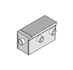
Insertion Tool
Application Tooling
Specification Sheet
Order No. 62202-9745
FEATURES
�
�
�
Lightweight tool used in the insertion of a SFP connector in a PCB
Inserts connector to a PCB without damage to the board
Use tool 62202-9750 for removing connectors
SCOPE
Products: Small Form-factor Pluggable (SFP+) One Piece Cage, Single Port Connector with Press-fit PC Tails.
Connector
Series No.
74737
Connector Order no.
74737-0001
74737-0009
74737-0031
74737-0037
74737-9998
74737-0002
74737-0012
74737-0032
74737-0201
74737-9999
74737-0003
74737-0014
74737-0033
74737-0203
74737-0004
74737-0019
74737-0034
74737-9993
74737-0005
74737-0020
74737-0035
74737-9994
74737-0006
74373-0029
74737-0036
74737-9997
Notes:
1. See the following pages for tooling operation instructions.
2. These tools require a “Keep Out Zone” around the connector free of components. The rear of the connector
should be .200” (5.08mm). The right and left sides should be .080” (2.00mm). See Figure 1.
CONNECTOR ASSEMBLY
5.08mm Minimum
PCB
2.0mm Minimum
(BOTH SIDES)
KEEP OUT
ZONE
Doc. No: ATS-622029745
Revision: A
Release Date: 06-20-11
Revision Date: 06-20-11
Figure 1
UNCONTROLLED COPY
Page 1 of 2
�SFP+ Multi-Port Connector Tooling
Description
The following Instructions are used for inserting the 1 by 1 connector into a PCB.
Operation
1. Place a connector assembly on the PCB.
2. Place the tool on the connector assembly (closed end to the back end of the connector). See Figure 2.
3. Place tool, connector, and PCB, in a press of suitable size and force, and seat the connector assembly
shown. The support under the PCB must have clearance for the connector pins if they come through the
PCB.
INSERTION TOOL
OVER CONNECTOR ASSEMBLY
Figure 2
INSERTION TOOL
(CLOSED END)
CONNECTOR
ASSEMBLY
PCB
BOTTOM OF CONNECTOR TO
SEAT FLUSH ON PCB
http://www.molex.com
Doc. No: ATS-622029745
Revision: A
Release Date: 06-20-11
Revision Date: 06-20-11
UNCONTROLLED COPY
Page 2 of 2
�
很抱歉,暂时无法提供与“0622029745”相匹配的价格&库存,您可以联系我们找货
免费人工找货- 国内价格 香港价格
- 1+5980.098991+774.24395