Tool Kit for Pico-SPOX™ Crimp Terminals
TYPE 2C
Application Tooling
Specification Sheet
Tool Kit
Order No. 63811-6470
Hand Crimp Tool
Order No. 63811-6400
FEATURES
A full cycle ratcheting hand tool ensures complete crimps
% Ergonomically designed soft handles
% Precisely designed crimping profiles with simple contact positioning
% Easy handling due to outstanding force ratio
� Tool kits are easily installed into the Hand Crimp Tool or the 63816-0300 Power Crimp Head which is installed
into the 63816-0200 (110 V) or the 63816-0250 (220 V) Battery Powered Tool.
� Many different Tool kits can be used with a single Battery Powered Tool.
� This tool is IPC/WHMA-A-620 Class 2 and RoHS compliant.
%
SCOPE
Products: 1.50mm (.059") Pico-SPOX™ Crimp Terminal, Female, 24-30 AWG.
Terminal
Series No.
Terminal Order No.
Wire Size
�Available in Reel form only
mm²
0.20
�Insulation Diameter
Maximum
mm
In.
1.15
.045
AWG
Type
24
UL1061
26
UL1061
87421-0000
26-30 0.12-0.05
28
UL1061
1.00
.039
30
UL1571
�Customer to cut off terminal from reel: 0.29mm (.011”) maximum Cut-off Tab.
�See Conditions on page 2.
87421
AWG
24
Wire Type
DEFINITION OF TERMS
BRUSH
Strip Length
mm
1.05-1.54
In.
.041-.061
1.05-1.54
.041-.061
BEND UP
BELL MOUTH
CONDUCTOR
CRIMP
INSULATION
CRIMP
▲SEE NOTE
ROLLING
TWISTING
STRIP
LENGTH
BEND
DOWN
CRIMP HEIGHT
Doc No: ATS-6381164HM Release Date: 06-19-06
Revision: C
Revision Date: 10-06-10
UNCONTROLLED COPY
Page 1 of 9
�Tool Kit for Pico-SPOX™ Crimp Terminals
▲Insulation Crimp Note:
OVERLAP FORM GEOMETRY
PUNCH
Due to the terminal’s insulation grip design
and/or insulation diameter range, this tool
uses “overlap” form geometry in the
insulation punch. This produces an overlap
insulation crimp (A620 – compliant). While
the insulation punch profile may appear
“lopsided”, this is a normal condition for this
tool. See figure to the right. (Some tools with
multiple crimp pockets may not have the
“overlap” profile on all pockets).
After crimping, the conductor profiles should
measure the following (see notes below).
OVERLAP
INSULATION
CRIMP
WIRE
ANVIL
●Insulation Crimp
Conductor Crimp
Pull Force
�Profile
Height (Ref.)
Width (Ref.) Height (Ref.) Width (Ref.) Minimum
AWG mm2
mm
In.
mm
In.
mm
In.
mm
In.
N
Lb. A
B
24 0.20 0.56-0.60 .022-.024 1.00 .039 1.40 .055 1.10 .043 29.4 6.60 X
26 0.12 0.52-0.58 .020-.023 1.00 .039 1.24 .049 1.10 .043 19.6 4.40
X
87421
28 0.08 0.52-0.58 .020-.023 1.00 .039 1.24 .049 1.10 .043 9.8 2.20
X
30 0.05 0.52-0.58 .020-.023 1.00 .039 1.24 .049 1.10 .043 6.7 1.50
X
�To Achieve IPC-A-620 Class 2 Crimps, the following over-all wire insulation diameter ranges are recommended:
Profile A: 1.00-1.15mm (.039-.045 inch)
Profile B: 0.65-1.00mm (.025-.039 inch)
Terminal Series No
Wire Size
Tool Qualification Notes:
1. Pull Force should be measured with no influence from the insulation crimp.
2. The above specifications are guidelines to an optimum crimp.
Note:
A crimp height chart is provided with this manual as Reference Only. Due to the wide range of wires, strands,
insulation diameters, and durometers, actual crimp height measurements may very slightly. An occasional,
destructive, pull force test should be preformed to check hand tool crimp. Pull Force value Must exceed the
Minimum pull force specifications listed this page.
CAUTION: Install only Molex terminals listed above with this tool. Do not crimp hardened objects as damage
can occur to the tool or die.
INSTALLATION
To install the Tool Kit into the Power Crimp Head follow the steps below:
Anvils and Punches Installation
1. Insert the Anvils into the bottom slots of the nest. Install the M4 x 10 long BHCS and tighten in place.
2. Insert the Punches into the top slots of the nest. Install the M4 x 18 long BHCS and tighten in place. See
Figure 1.
Doc No: ATS-6381164HM Release Date: 06-19-06
Revision: C
Revision Date: 10-06-10
UNCONTROLLED COPY
Page 2 of 9
�Tool Kit for Pico-SPOX™ Crimp Terminals
POWER
CRIMP
HEAD
PUNCHES
M4 X 18 LONG
BHCS
LIFT UP ON
THE LOCATOR
PRESS DOWN
ON THE BRASS
PIVOT SHAFT
M4 X 10 LONG
BHCS
Figure 1
ANVILS
SWING
LOCATOR
OPEN
Figure 2
Locator Installation and Removal
Follow the steps below to install or replace the locator. See Figure 2.
To install the locator
1. Position the locator with the hole over the brass pivot shaft and
snap it into place.
JAWS OPEN
LOCATOR
To remove the locator
1. Open the crimp hand tool.
2. Swing the existing locator open and away from the hand tool.
3. Firmly press down on the brass pivot shaft with your thumb,
while pulling the locator up. Slip the locator off the top of the
brass pivot shaft.
OPERATION
Figure 3
Open the tool by squeezing the handles together, at the end of the closing stroke, the ratchet mechanism will
release the handles, and the hand tool will spring open.
FRAME
SWING OPEN
TERMINAL
PRESS HERE ON LOCATOR
LOCATOR
TERMINAL IN PLACE
Figure 4
Doc No: ATS-6381164HM Release Date: 06-19-06
Revision: C
Revision Date: 10-06-10
UNCONTROLLED COPY
Page 3 of 9
�Tool Kit for Pico-SPOX™ Crimp Terminals
Crimping Terminals
1. Select the desired terminal listed in the preceding charts.
2. Swing the terminal locator away from the crimp tool shown in
WIRE STOP
Figure 4. Gently press on the locator to open the wire stop.
WIRE
Some terminals with large insulation grips may interfere with the
crimp tooling when swinging the locator into position. The
terminal must then be loaded into the locator in the closed/crimp
position.
3. When using the locator, swing the locator away from the crimp
tool, and gently press the locator against the tool frame as
shown in Figure 4. The wire stop will automatically open. Insert LOCATOR
IN PLACE WIRE STOP
TERMINAL
the proper terminal into the proper nest opening. Make sure
when choosing the nest opening, it will correspond with the A or
B profile on the hand tool.
4. Return the locator to its original position.
5. Insert the proper wire over the terminal. Some large O.D. wires
may need to be placed into the terminal before closing the tool.
Gently touch the wire stop with the end of the wire. See Figure
WIRE
5.
AGAINST STOP
6. Compress the terminal by squeezing the tool handles until the
Figure 5
ratchet mechanism cycle has been completed. Release
handles to open the jaws.
7. Remove the crimped terminal from the terminal locator by pressing down on the wire stop and gently pulling on
the wire. The terminal locator can be in either position.
8. Visually inspect the crimped terminal for proper crimp location.
Note: The tamper proof ratchet action will not release the tool until it has been fully closed.
LIFT UP
LOCATOR
Locator Replacement
See the parts list on the last page of this document for the
proper locator order number. Follow the steps below to replace
the locator.
1. Open the crimp hand tool.
2. Swing the existing locator open and away from the hand
tool.
3. Firmly press down on the brass pivot shaft with your
thumb, while pulling the locator up. Slip the locator off the
top of the brass pivot shaft. See Figure 6.
4. Replace it with the proper locator by putting over the brass
pivot shaft and snapping it into place.
JAWS
OPEN
PRESS DOWN
ON BRASS PIVOT
SHAFT
SWING
LOCATOR
OPEN
Figure 6
For the Battery Power Tool:
1. Cycle the Battery Power Tool to crimp the terminal to the wire.
2. Remove the crimped terminal from the terminal locator by pressing down on the wire stop and gently pulling on
the wire. The terminal locator can be in either position.
3. Visually inspect the crimped terminal for proper crimp location.
Doc No: ATS-6381164HM Release Date: 06-19-06
Revision: C
Revision Date: 10-06-10
UNCONTROLLED COPY
Page 4 of 9
�Tool Kit for Pico-SPOX™ Crimp Terminals
Maintenance
It is recommended that each operator of the
tool be made aware of, and responsible for,
the following maintenance steps:
Figure 7B
1. Remove dust, moisture, and other
contaminants with a clean brush, or soft,
lint free cloth.
LUBRICATION
POINTS
2. Do not use any abrasive materials that
(BOTH SIDES)
could damage the tool.
LIGHT OIL
3. Make certain all pins; pivot points and
(EVERY MONTH
bearing surfaces are protected with a thin
OR
coat of high quality machine oil. Do not oil
5,000 CRIMPS)
excessively. The tool was engineered for
Figure 7A
durability but like any fine piece of
equipment it needs cleaning and
lubrication for a maximum service life of trouble free crimping. Use a 30 weight automotive (light) oil used at
the oil points, every 5,000 crimps or 3 months, shown in Figure 7A or 7B will significantly enhance the tool life.
4. Wipe excess oil from hand tool, particularly from crimping area. Oil transferred from the crimping area onto
certain terminations may affect the electrical characteristics of an application.
5. When tool is not in use, keep the handles
closed to prevent objects from becoming
PRELOAD
CHECK POINT
lodged in the crimping dies, and store the tool
25.4MM
in a clean, dry area.
Miscrimps or Jams
SETTING WHEEL
ECCENTRIC AXLE
Should this tool ever become stuck or jammed in a
partially closed position, Do Not force the handles
open or closed. The tool will open easily by
pressing the ratchet release lever. See Figure 8.
How to Adjust Tool Preload
(See Figure 8)
HANDLE
GRIP
REMOVED
WRENCH SET
(SOLD
SEPERATELY)
LOCKING
SCREW
HANDLE
GRIP
RATCHET
RELEASE LEVER
Figure 8
This hand tool is factory preset to 25-45 LBS.
preload. It may be necessary over the life of the tool to adjust tool handle preload force. Listed below are the
steps required to adjust the crimping force of the hand tool to obtain proper crimp conditions:
1. Remove or fold back the handle grip from the handle to expose the eccentric axle and setting wheel.
2. Remove the locking screw with a 2mm hex wrench. The wrench set (63810-0101), is not supplied. It is sold
separately from the hand tool.
3. Turn the eccentric axle and setting wheel with the wrench or pliers Counter-clockwise (CCW) to increase
handle force.
4. Replace the locking screw, aligning the nearest notch in the setting wheel to locking screw.
5. Replace the handle grip.
6. Check the crimp specifications or conduct a pull test after tool handle preload force is adjusted.
Doc No: ATS-6381164HM Release Date: 06-19-06
Revision: C
Revision Date: 10-06-10
UNCONTROLLED COPY
Page 5 of 9
�Tool Kit for Pico-SPOX™ Crimp Terminals
Warranty
This tool is for electrical terminal crimping purposes only. This tool is made of the best quality materials. All vital
components are long life tested. All tools are warranted to be free of manufacturing defects for a period of 30
days. Should such a defect occur, we will repair or exchange the tool free of charge. This repair or exchange will
not be applicable to altered, misused, or damaged tools. This tool is designed for hand use only. Any clamping,
fixturing, or use of handle extensions voids this warranty.
CAUTION: Molex crimp specifications are valid only when used with Molex terminals and tooling.
CAUTIONS
1. Manually powered hand tools are intended for low volume or field repair. This tool is NOT intended for
production use. Repetitive use of this tool should be avoided.
2. Insulated rubber handles are not protection against electrical shock.
3. Wear eye protection at all times.
4. Use only the Molex terminals specified for crimping with this tool.
Certification
Molex does not certify or re-certify commercial grade hand tools but rather supplies the following guidelines for
customers to re-certify hand tools.
% This tool is qualified to pull force only. To re-certify, crimp a terminal to a wire, which has been stripped
12.7mm (1/2”) long, so there is no crimping of the insulation. Pull the terminal and wire at a rate no faster than
25mm (1.00”) per minute. See the Molex web site for the Quality Crimp Handbook for more information on pull
testing.
% If the tool does not meet minimum pull force values, handle preload should be increased and the pull test
rerun, (See How To Adjust Preload).
% When the hand tool is no longer capable of achieving minimum pull force, it should be taken out of service and
replaced.
Doc No: ATS-6381164HM Release Date: 06-19-06
Revision: C
Revision Date: 10-06-10
UNCONTROLLED COPY
Page 6 of 9
�Tool Kit for Pico-SPOX™ Crimp Terminals
The chart below shows all applications for this Tool Kit.
Adapter
Figure
Tool
Tool
Power Head
Order No.
Description
No.
Order no.
Description
63810-0100 Hand Crimp Frame (Short)
N/A
N/A
9
63810-0400 Hand Crimp Frame (Long)
N/A
N/A
9
63811-6470
63816-0200 Battery Power Tool (110 V) 63816-0300 Power Crimp Head
10
63816-0250 Battery Power Tool (220 V) 63816-0300 Power Crimp Head
10
Tool Kit
Order No.
Applications for the Tool Kit
Hand Crimp Tool
Battery Powered Tool
POWER
CRIMP
HEAD
TOOLING KIT
TOOLING
KIT
HAND CRIMP
FRAME LONG
AND SHORT
BATTERY
POWERED
TOOL
Figure 9
LOCKING PINS
Figure 10
WARNING: NEVER operate service, install tool kits, or adjust the Power Crimp Head without proper
instruction and without first reading and understanding the instructions in the proper Manual or
Specification Sheet. See Chart above for the correct Manual or Specification Sheet.
WARNING: NEVER install tooling or service this tool while it is into any power source. Make sure the
power is turned off.
CAUTION: Keep fingers away from the crimping area when operating this tool. It may cause severe injury.
CAUTION: Wear safety glasses when operating or serving this tool.
Doc No: ATS-6381164HM Release Date: 06-19-06
Revision: C
Revision Date: 10-06-10
UNCONTROLLED COPY
Page 7 of 9
�Tool Kit for Pico-SPOX™ Crimp Terminals
HAND TOOL PARTS LIST
Item Number
1
2
3
4
5
6
6
LOCATOR ONLY
5
WITH TOOL KIT
Order Number
63810-0100
63810-0101
63810-0102
63810-0103
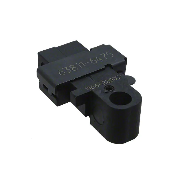
63811-6470
63811-6475
Description
Hand Crimp Frame (Short)
Wrench Set (Not included)
Locator Base
Repair Kit (Not included)
Tool Kit with Locator
Locator (only)
Quantity
1
0
1
0
1
REF
2
4
3
1
M4 X 6mm
LONG BHCS
RATCHET
RELEASE SCREW
Figure 11
4
5
M4 X 12mm
LONG BHCS
Doc No: ATS-6381164HM Release Date: 06-19-06
Revision: C
Revision Date: 10-06-10
M4 X 12mm
LONG BHCS
UNCONTROLLED COPY
Page 8 of 9
�Tool Kit for Pico-SPOX™ Crimp Terminals
POWER HEAD PARTS LIST
Item
1
2
Order No
63816-0300
63811-6470
Engineering No.
63816-0300
63811-6470
Description
Power Crimp Head
Tool Kit
Quantity
1
1
2
1
1
M4 by 8 Long
BHCS
M4 by 18 Long
BHCS
M4 by 10 Long
BHCS
2
Figure 12
http://www.molex.com
Doc No: ATS-6381164HM Release Date: 06-19-06
Revision: C
Revision Date: 10-06-10
UNCONTROLLED COPY
Page 9 of 9
�