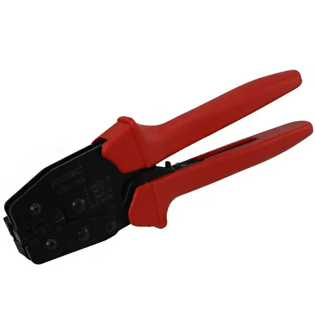
Hand Tool for .093" Pin and Socket Crimp Terminals and Claspcon™ Crimp Terminal Socket
HAND CRIMP TOOL
SPECIFICATION SHEET
Order No. 63811-7100
TYPE 2C
FEATURES
�
�
�
�
A full cycle ratcheting hand tool ensures complete crimps
Ergonomic soft grip handles for comfortable crimping
A precision user-friendly terminal locator wire stop holds terminals in the proper crimping position
This tool is IPC/WHMA-A-620 Class 2 and RoHS compliant
SCOPE
Products: .093” Pin and Socket 14-18 AWG and 24-30 AWG and Claspcon™ Crimp Terminal Socket 24-30 AWG
�
Terminal Order No.
Wire Size
Insulation Diameter
Strip Length
Loose Piece
Reel
AWG
mm²
mm
In.
mm
In.
02-09-1141 39-00-0318 02-09-1142 39-00-0317
02-09-1144 39-00-0320 02-09-5146 39-00-0319
24-30 0.20-0.05 0.76-1.52 .030-.060 3.96-5.53 .156-.218
1433
02-09-5147 39-00-0322 39-00-0315 39-00-0321
39-00-0316
02-09-2143 39-00-0324 02-09-2141 39-00-0325
1434
02-09-6145 39-00-0326 02-09-2149 39-00-0323 24-30 0.20-0.05 0.76-1.52 .030-.060 3.96-5.53 .156-.218
02-09-6144
1881-3
02-08-1104
02-08-1103
24-30 0.20-0.05 0.76-1.52 .030-.060 3.96-5.53 .156-.218
42477
02-09-1615
14-18 2.00-0.80 2.36-3.55 .093-.140 3.96-5.53 .156-.218
42478
02-09-2612
02-09-2611
14-18 2.00-0.80 2.36-3.55 .093-.140 3.96-5.53 .156-.218
Follow the Cut-Off Tab specifications on Applicator specification sheets. These Terminals in the 1433, 1434, and 1881 series
cannot be removed from the reel by manual cutting. An applicator must be used or the terminals will not function properly.
See Conditions on page 2.
Terminal
Series No.
�
�
�
DEFINITION OF TERMS
BRUSH
BEND UP
BELL MOUTH
CONDUCTOR
CRIMP
INSULATION
CRIMP
ROLLING
TWISTING
STRIP
LENGTH
BEND
DOWN
CRIMP HEIGHT
The above terminal drawing is a generic terminal representation. It is not an image of a terminal listed in the
scope.
Doc No: ATS-638117100
Revision: B
Release Date: 02-12-07
Revision Date: 03-28-08
UNCONTROLLED COPY
Page 1 of 6
�Hand Tool for .093" Pin and Socket Crimp Terminals and Claspcon™ Crimp Terminal Socket
CONDITIONS:
After crimping, the conductor profiles should measure the following (see Note).
Conductor Crimp
Wire Size
Terminal Series No.
AWG
�
mm
2
Height (Ref)
mm
In.
Insulation Crimp
Height (Ref)
Width (Ref)
Width (Ref)
Maximum
mm
In.
mm
In.
mm
In.
Pull Force
Minimum
N
�Profile
Lb. A B C
24 0.20 0.86-0.94 .034-.037 1.60 .063 1.35 .053 1.90 .075 33.5 10.00 X
26 0.12 0.86-0.94 .034-.037 1.60 .063 1.32 .051 1.90 .075 20.1 6.00 X
1433
28 0.08 0.86-0.94 .034-.037 1.60 .063 1.28 .050 1.90 .075 13.3 3.00 X
30 0.05 0.84-0.91 .033-.036 1.60 .063 1.28 .050 1.90 .075 6.7 1.50 X
24 0.20 0.86-0.94 .034-.037 1.60 .063 1.35 .053 1.90 .075 33.5 10.00 X
26 0.12 0.86-0.94 .034-.037 1.60 .063 1.32 .051 1.90 .075 20.1 6.00 X
1434
28 0.08 0.86-0.94 .034-.037 1.60 .063 1.28 .050 1.90 .075 13.3 3.00 X
30 0.05 0.84-0.91 .033-.036 1.60 .063 1.28 .050 1.90 .075 6.7 1.50 X
24 0.20 0.86-0.94 .034-.037 1.60 .063 1.35 .053 1.90 .075 33.5 10.00 X
26 0.12 0.86-0.94 .034-.037 1.60 .063 1.32 .051 1.90 .075 20.1 6.00 X
1881-3
28 0.08 0.86-0.94 .034-.037 1.60 .063 1.28 .050 1.90 .075 13.3 3.00 X
30 0.05 0.84-0.91 .033-.036 1.60 .063 1.28 .050 1.90 .075 6.7 1.50 X
14 2.00 1.85-1.96 .073-.077 2.49 .098 3.28 .129 4.85 .191 222.6 50.00
X
42477
16 1.30 1.40-1.50 .055-.059 2.75 .108 3.80 .150 3.70 .146 133.5 30.00
18 0.80 1.30-1.40 .051-.055 2.75 .108 3.75 .148 3.70 .146 89.0 20.00
14 2.00 1.85-1.96 .073-.077 2.49 .098 3.28 .129 4.60 .181 222.6 50.00
X
42478
16 1.30 1.40-1.50 .055-.059 2.75 .108 3.80 .150 3.70 .146 133.5 30.00
18 0.80 1.30-1.40 .051-.055 2.75 .108 3.75 .148 3.70 .146 89.0 20.00
To Achieve IPC-A-620 Class 2 Crimps, the following over-all wire insulation diameter ranges are recommended:
1. Profile A: 0.76-1.52mm (.030-.060 inch)
2. Profile B: 2.79-3.55mm (.110-.140 inch)
3. Profile C: 2.36-3.14mm (.093-.124 inch)
X
X
X
X
OPERATION
CAUTION: Install only Molex terminals listed above with this tool. Do not crimp hardened objects as
damage can occur to the tool or die.
Open the tool by squeezing the handles together, at the end of the closing
stroke, the ratchet mechanism will release the handles, and the hand tool will
spring open.
JAWS OPEN
LOCATOR
Crimping Terminals
1. Select the desired terminal listed in the preceding charts.
2. Swing the terminal locator away from the crimp tool shown in Figure 2.
Some terminals with large insulation grips may interfere with the crimp
tooling when swinging the locator into position. The terminal must then
be loaded into the locator in the closed/crimp position.
Doc No: ATS-638117100
Revision: B
Release Date: 02-12-07
Revision Date: 03-28-08
UNCONTROLLED COPY
Figure 1
Page 2 of 6
�Hand Tool for .093" Pin and Socket Crimp Terminals and Claspcon™ Crimp Terminal Socket
3. When using the locator, press down on the wire stop on the locator as shown in Figure 2. Insert the proper
terminal into the proper nest opening. Make sure when choosing the nest opening, it will correspond with the
A, B, or C profile on the hand tool.
4. Return the locator to its original position. Insert the proper wire over the terminal. Some large O.D. wires may
need to be placed into the terminal before closing the tool. Gently touch the wire stop with the end of the wire.
See Figure 3.
5. Compress the terminal by squeezing the tool handles until the ratchet mechanism cycle has been completed.
Release handles to open the jaws.
Note: The tamper proof ratchet action will not release the tool until it has been fully closed.
6. Remove the crimped terminal from the terminal locator by pressing
down on the wire stop and gently pulling on the wire. The terminal
locator can be in either position.
WIRE STOP
7. Visually inspect the crimped terminal for proper crimp location.
WIRE
TERMINAL
LOCATOR
IN PLACE
SWING OPEN
TERMINAL
WIRE STOP
PUSH HERE
TO OPEN LOCATOR
WIRE STOP
LOCATOR
Figure 2
TERMINAL
IN PLACE
Note:
A crimp height chart is provided with this manual as Reference Only. Due
to the wide range of wires, strands, insulation diameters, and
durometers, actual crimp height measurements may very slightly.
An occasional, destructive, pull force test should be preformed to
check hand tool crimp. Pull Force value Must exceed the
Minimum pull force specifications listed under Conditions.
Locator Replacement
See the parts list on the last page of this document for the proper
locator order number. Follow the steps below to replace the
locator.
WIRE AGAINST
STOP
LIFT UP LOCATOR
Release Date: 02-12-07
Revision Date: 03-28-08
JAWS
OPEN
PRESS DOWN
ON BRASS
PIVOT SHAFT
SWING
1. Open the crimp hand tool.
LOCATOR
2. Swing the existing locator open and away from the hand tool.
OPEN
3. Firmly press down on the brass pivot shaft with your thumb,
while pulling the locator up. Slip the locator off the top of the
brass pivot shaft. See Figure 4.
4. Replace it with the new locator by putting over the brass pivot shaft and snapping it into place.
Doc No: ATS-638117100
Revision: B
Figure 3
UNCONTROLLED COPY
Figure 4
Page 3 of 6
�Hand Tool for .093" Pin and Socket Crimp Terminals and Claspcon™ Crimp Terminal Socket
Maintenance
LUBRICATION POINTS
(BOTH SIDES) LIGHT OIL
(EVERY 3 MONTHS OR
5,000 CRIMPS)
It is recommended that each operator of the tool be made aware
of, and responsible for, the following maintenance steps:
1. Remove dust, moisture, and other contaminants with a clean
brush, or soft, lint free cloth.
2. Do not use any abrasive materials that could damage the
tool.
3. Make certain all pins; pivot points and bearing surfaces are
protected with a thin coat of high quality machine oil. Do not
Figure 5
oil excessively. The tool was engineered for durability but
like any fine piece of equipment it needs cleaning and
lubrication for a maximum service life of trouble free crimping. Use light oil, such as 30 weight automotive oil, at
the oil points. Every 5,000 crimps, or 3 months, to significantly enhance the tool life. See Figure 6.
4. Wipe excess oil from hand tool, particularly from crimping area. Oil transferred from the crimping area onto
certain terminations may affect the electrical characteristics of an application.
5. When tool is not in use, keep the handles closed to prevent objects from becoming lodged in the crimping dies,
and store the tool in a clean, dry area.
Miscrimps or Jams
Should this tool ever become stuck or jammed in a
partially closed position, Do Not force the handles
open or closed. The tool will open easily by
pressing the ratchet release lever. See Figure 6.
PRELOAD
CHECK POINT
25.4MM
SETTING WHEEL
ECCENTRIC AXLE
How to Adjust Tool Preload
(See Figure 6)
This hand tool is factory preset to 25-45 LBS.
preload. It may be necessary over the life of the
WRENCH SET
tool to adjust tool handle preload force. Listed
(SOLD
LOCKING
below are the steps required to adjust the crimping
SEPERATELY) SCREW
force of the hand tool to obtain proper crimp
conditions:
HANDLE
GRIP
REMOVED
HANDLE
GRIP
RATCHET
RELEASE LEVER
Figure 6
1. Remove or fold back the handle grip from the handle to expose the eccentric axle and setting wheel.
2. Remove the locking screw with a 2mm hex wrench. The wrench set (63810-0101), is not supplied. It is sold
separately from the hand tool.
3. Turn the eccentric axle and setting wheel with the wrench or pliers Counter-clockwise (CCW) to increase
handle force.
4. Replace the locking screw, aligning the nearest notch in the setting wheel to locking screw.
5. Replace the handle grip.
6. Check the crimp specifications or conduct a pull test after tool handle preload force is adjusted.
Doc No: ATS-638117100
Revision: B
Release Date: 02-12-07
Revision Date: 03-28-08
UNCONTROLLED COPY
Page 4 of 6
�Hand Tool for .093" Pin and Socket Crimp Terminals and Claspcon™ Crimp Terminal Socket
Warranty
This tool is for electrical terminal crimping purposes only. This tool is made of the best quality materials. All vital
components are long life tested. All tools are warranted to be free of manufacturing defects for a period of 30
days. Should such a defect occur, we will repair or exchange the tool free of charge. This repair or exchange will
not be applicable to altered, misused, or damaged tools. This tool is designed for hand use only. Any clamping,
fixturing, or use of handle extensions voids this warranty.
CAUTION: Molex crimp specifications are valid only when used with Molex terminals and tooling.
CAUTIONS:
1. Manually powered hand tools are intended for low volume or field repair. This tool is NOT intended for
production use. Repetitive use of this tool should be avoided.
2. Insulated rubber handles are not protection against electrical shock.
3. Wear eye protection at all times.
4. Use only the Molex terminals specified for crimping with this tool.
Certification
Molex does not certify or re-certify commercial grade hand tools but rather supplies the following guidelines for
customers to re-certify hand tools.
% This tool is qualified to pull force only. To re-certify, crimp a terminal to a wire, which has been stripped
12.7mm (1/2”) long, so there is no crimping of the insulation. Pull the terminal and wire at a rate no faster than
25mm (1.00”) per minute. See the Molex web site for the Quality Crimp Handbook for more information on pull
testing.
% If the tool does not meet minimum pull force values, handle preload should be increased and the pull test
rerun, (See How to Adjust Preload).
% When the hand tool is no longer capable of achieving minimum pull force, it should be taken out of service and
replaced.
Doc No: ATS-638117100
Revision: B
Release Date: 02-12-07
Revision Date: 03-28-08
UNCONTROLLED COPY
Page 5 of 6
�Hand Tool for .093" Pin and Socket Crimp Terminals and Claspcon™ Crimp Terminal Socket
PARTS LIST
Item Number
REF
1
2
3
4
Order Number
63811-7100
63810-0101
63810-0102
63810-0103
63811-7175
Description
Hand Crimp Tool
Wrench Set (Not included)
Locator Base Assembly
Repair Kit (Not included)
Locator
Quantity
Figure 7
0
1
0
1
1
3
4
M4 X 5LG
BHCS
RATCHET
RELEASE LEVER
2
3
Figure 7
Americas Headquarters
Lisle, Illinois 60532 U.S.A.
1-800-78MOLEX
amerinfo@molex.com
Far East North Headquarters
Yamato, Kanagawa, Japan
81-462-65-2324
feninfo@molex.com
Far East South Headquarters
Jurong, Singapore
65-6-268-6868
fesinfo@molex.com
European Headquarters
Munich, Germany
49-89-413092-0
eurinfo@molex.com
Corporate Headquarters
2222 Wellington Ct.
Lisle, IL 60532 U.S.A.
630-969-4550
Fax: 630-969-1352
Visit our Web site at http://www.molex.com
Doc No: ATS-638117100
Revision: B
Release Date: 02-12-07
Revision Date: 03-28-08
UNCONTROLLED COPY
Page 6 of 6
�