Tool Kit for KK Crimp Terminals
TYPE 2C
Tool Kit
Order No. 63811-7570
Application Tooling
Specification Sheet
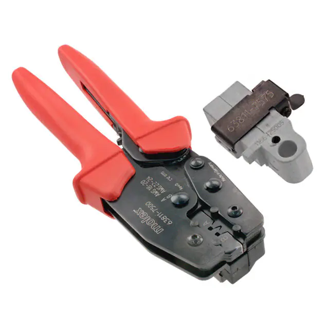
Hand Crimp Tool
Order No. 63811-7500
FEATURES
%
%
%
%
%
%
%
%
A full cycle ratcheting hand tool ensures complete crimps
Ergonomically designed soft handles
Precisely designed crimping profiles with simple contact positioning
Easy handling due to outstanding force ratio
Tool kits are easily installed into the Hand Crimp Tool or the 63816-0300 Power Crimp Head, which is installed
into the 63816-0200 (110 V) or the 63816-0250 (220 V) Battery Powered Tool
Many different Tool kits can be used with a single Battery Powered Tool
This tool is IPC/WHMA-A-620 Class 2 and RoHS compliant as indicated
Both black and gray locators are included with hand tool
SCOPE
Products: 3.96mm (.156") Pitch KK Crimp Terminal for 18-24 AWG.
Terminal Order No.
Wire Size
Terminal
Series No.
Loose Piece
Reel
AWG
mm2
2477
08-50-0110 08-56-0114 08-50-0109 08-56-0113 18-24 0.80-0.20
08-50-0006 08-56-0106 08-50-0001 08-52-0073
08`-50-0016 08-56-0154 08-50-0014 08-52-0114
08-50-0045 08-58-0104 08-50-0015 08-52-0811
08-50-0046 08-58-0115 08-50-0047 08-53-0004
08-50-0056 08-58-0122 08-50-0055 08-53-0811
08-50-0064 08-65-0115 08-50-0063 08-55-0103
08-50-0074 39-00-0345 08-50-0073 08-55-0133
08-50-0093 39-00-0344 08-50-0091 08-56-0105
08-50-0106 39-00-0346 08-50-0103 08-56-0153
08-50-0120 39-00-0348 08-50-0105 08-58-0103
2478
08-50-0147 40-01-1120 08-50-0119 08-58-0114 18-24 0.80-0.20
08-52-0024 50-29-1762 08-50-0146 08-58-0121
08-52-0045 50-30-4428 08-50-0271 08-65-0114
08-52-0047 50-30-4429 08-50-0281 39-00-0286
08-52-0072
08-51-0000 39-00-0343
08-52-0074
08-51-0720 39-00-0345
08-52-0115
08-52-0023 39-00-0347
08-52-0812
08-52-0027 40-01-1118
08-53-0812
08-52-0044 50-29-1689
08-55-0104
08-52-0046 50-29-1768
08-55-0134
08-52-0071
Doc No: ATS-6381175HM
Revision: K
Release Date: 12-06-06
Revision Date: 08-03-17
Insulation Diameter
Strip Length
mm
In.
mm
In.
1.39-2.79 .055-.110 2.54-3.17 .100-.125
1.39-2.79 .055-.110 2.54-3.17 .100-.125
UNCONTROLLED COPY
Page 1 of 12
�Tool Kit for KK Crimp Terminals
Terminal
Series No.
2878
838
5167
6348
6838
8818
8993
172160
Terminal Order No.
Wire Size
Insulation Diameter
Loose Piece
Reel
AWG
mm2
mm
In.
08-50-0116
08-50-0115 08-55-0138
08-52-0127
08-51-0109 08-58-0127
18-20 0.80-0.50 1.52-2.79 .060-.110
08-58-0128
08-52-0126 08-65-0118
08-65-0119
08-53-0814
08-50-0132 08-55-0143 08-50-0131 08-55-0142
08-55-0140 08-55-0146 08-55-0125 08-55-0145 18-22 0.80-0.35 1.52-2.41 .060-.095
08-55-0141 08-55-0148 08-55-0139 08-55-0147
08-70-0013 08-70-1034 08-70-0012 08-70-0097 18-24 0.80-0.20 1.39-2.48 .055-.098
08-50-0165 08-56-0139 08-50-0164 08-53-0813
08-51-0802
08-51-0801 08-56-0135 18-20 0.80-0.50 1.52-2.41 .060-.095
08-56-0133
08-51-0813 08-56-0137
08-50-0029 08-58-0119 08-50-0024 08-58-0105
08-50-0189 08-58-0132 08-50-0026 08-58-0108
08-50-0251 08-58-0189 08-50-0028 08-58-0110
08-51-0107 08-60-0002 08-50-0187 08-58-0118
08-52-0113 50-29-1763 08-50-0275 08-58-0131 18-20 0.80-0.50 1.52-2.79 .060-.110
08-53-1102 50-29-1879 08-51-0106 08-58-0187
08-58-0106
08-52-0112 08-60-0001
08-58-0109
08-53-0101 50-29-1639
08-58-0111
08-58-0102
08-50-0023 08-58-0136 08-50-0008 08-58-0135
08-50-0706 08-65-0129 08-50-0705 08-65-0128
18-22 0.80-0.35 1.52-2.79 .060-.110
08-52-0132
08-52-0131 40-01-1181
08-56-0188
08-56-0187 40-01-1182
08-50-0276
08-50-0011 08-50-0277 18-24 0.80-0.20 1.39-2.79 .055-.110
172160-1803 172160-1804
172160-1801 172160-1802 18-20 0.80-0.50 1.52-2.79 .060-.110
172160-1805 172160-1806
Customer to cut off terminal from reel: 2.72 ± .13mm (.107 ± .005”) maximum cut off tab.
See Conditions on page 4.
Strip Length
mm
In.
2.54-3.17 .100-.125
2.54-3.17 .100-.125
2.54-3.17 .100-.125
2.54-3.17 .100-.125
2.54-3.17 .100-.125
4.00-4.75 .157-.187
2.54-3.17 .100-.125
2.54-3.17 .100-.125
DEFINITION OF TERMS
CONDUCTOR CRIMP
INSULATION CRIMP ▲SEE NOTE
BEND UP
LOCKING
TANG HEIGHT
ROLLING
BRUSH
BELL
MOUTH
SEAM
TWISTING
CUT-OFF
TAB
STRIP LENGTH
BEND
DOWN
CRIMP HEIGHT
Doc No: ATS-6381175HM
Revision: K
Release Date: 12-06-06
Revision Date: 08-03-17
UNCONTROLLED COPY
Page 2 of 12
�Tool Kit for KK Crimp Terminals
OVERLAP FORM GEOMETRY
▲Insulation Crimp Note
PUNCH
Due to the terminal’s insulation grip design
and/or insulation diameter range, this tool
uses “overlap” form geometry in the
insulation punch. This produces an overlap
insulation crimp (A620 – compliant). While
the insulation punch profile may appear
“lopsided”, this is a normal condition for this
tool. See figure to the right. (Some tools with
multiple crimp pockets may not have the
“overlap” profile on all pockets).
OVERLAP
INSULATION
CRIMP
WIRE
ANVIL
CONDITIONS
After crimping, the conductor profiles should measure the following (see notes below):
Terminal
Series No.
Hand Tool
Locator
2477
Black
63811-7576
2478
Black
63811-7576
2878
Black
63811-7576
4838
Black
63811-7576
5167
Black
63811-7576
6438
Black
63811-7576
6838
Black
63811-7576
8818
Gray
63811-7575
Doc No: ATS-6381175HM
Revision: K
Wire Size
AWG
18
20
22
24
18
20
22
24
18
20
18
20
22
18
20
22
24
18
20
18
20
18
20
22
mm2
0.80
0.50
0.35
0.20
0.80
0.50
0.35
0.20
0.80
0.50
0.80
0.50
0.35
0.80
0.50
0.35
0.20
0.80
0.50
0.80
0.50
0.80
0.50
0.35
Conductor Crimp Height
(REF)
mm
In.
1.01-1.11
.040-.044
1.01-1.11
.040-.044
0.86-0.96
.034-.038
0.86-0.96
.034-.038
1.01-1.11
.040-.044
1.01-1.11
.040-.044
0.86-0.96
.034-.038
0.86-0.96
.034-.038
1.01-1.11
.040-.044
1.01-1.11
.040-.044
1.01-1.11
.040-.044
1.01-1.11
.040-.044
0.86-0.96
.034-.038
1.01-1.11
.040-.044
1.01-1.11
.040-.044
0.86-0.96
.034-.038
0.86-0.96
.034-.038
1.01-1.11
.040-.044
1.01-1.11
.040-.044
1.01-1.11
.040-.044
1.01-1.11
.040-.044
1.01-1.11
.040-.044
1.01-1.11
.040-.044
0.86-0.96
.034-.038
Release Date: 12-06-06
Revision Date: 08-03-17
Punch Width (Ref)
Conductor Insulation
mm
In.
mm
In.
2.00 .079 2.50 .098
2.00 .079 2.50 .098
2.00 .079 2.50 .098
2.00 .079 2.50 .098
2.00 .079 2.50 .098
2.00 .079 2.50 .098
2.00 .079 2.50 .098
2.00 .079 2.50 .098
2.00 .079 2.50 .098
2.00 .079 2.50 .098
2.00 .079 2.50 .098
2.00 .079 2.50 .098
2.00 .079 2.50 .098
2.00 .079 2.50 .098
2.00 .079 2.50 .098
2.00 .079 2.50 .098
2.00 .079 2.50 .098
2.00 .079 2.50 .098
2.00 .079 2.50 .098
2.00 .079 2.50 .098
2.00 .079 2.50 .098
2.00 .079 2.50 .098
2.00 .079 2.50 .098
2.00 .079 2.50 .098
UNCONTROLLED COPY
Pull Force
Minimum
N
Lb.
89.0 20.00
57.8 13.00
35.6 8.00
22.2 5.00
89.0 20.00
57.8 13.00
35.6 8.00
22.2 5.00
89.0 20.00
57.8 13.00
89.0 20.00
57.8 13.00
35.6 8.00
89.0 20.00
57.8 13.00
35.6 8.00
22.2 5.00
89.0 20.00
57.8 13.00
89.0 20.00
57.8 13.00
89.0 20.00
57.8 13.00
35.6 8.00
Profile
A
X
X
B
X
X
X
X
X
X
X
X
X
X
X
X
X
X
X
X
X
X
X
X
X
X
Page 3 of 12
�Tool Kit for KK Crimp Terminals
Terminal Hand Tool
Series No. Locator
8993
Black
638117576
Wire Size
AWG
18
20
22
24
18
mm2
0.80
0.50
0.35
0.20
0.80
Conductor Crimp Height
(REF)
mm
In.
1.01-1.11
.040-.044
1.01-1.11
.040-.044
0.86-0.96
.034-.038
0.86-0.96
.034-.038
1.01-1.11
.040-.044
Punch Width (Ref)
Conductor
Insulation
mm
In.
mm
In.
2.00 .079
2.50 .098
2.00 .079
2.50 .098
2.00 .079
2.50 .098
2.00 .079
2.50 .098
2.00 .079
2.50 .098
Pull Force
Minimum
N
Lb.
89.0 20.00
57.8 13.00
35.6 8.00
22.2 5.00
89.0 20.00
Profile
A
X
X
B
X
X
Black
X
6381120 0.50 1.01-1.11
.040-.044 2.00 .079
2.50 .098
57.8 13.00 X
7576
To Achieve IPC-A-620 Class 2 Crimps, the following overall wire insulation diameter ranges are recommended:
1.
Profile A: 1.70-2.00mm (.067-.079”)
2.
Profile B: 1.65-1.85mm (.065-.073”)
172160
Tool Qualification Notes
1. Pull force should be measured with no influence from the insulation crimp.
2. The above specifications are guidelines to an optimal crimp.
Note:
A crimp height chart is provided with this manual as reference only. Due to the wide range of wires, strands,
insulation diameters and durometers, actual crimp height measurements may very slightly. An occasional
destructive pull force test should be preformed to check hand tool crimp. Pull force value must exceed the minimum
pull force specifications listed.
CAUTION: Install only Molex terminals listed above with this tool. Do not crimp hardened objects because
damage can occur to the tool or die.
Doc No: ATS-6381175HM
Revision: K
Release Date: 12-06-06
Revision Date: 08-03-17
UNCONTROLLED COPY
Page 4 of 12
�Tool Kit for KK Crimp Terminals
OPERATION
TERMINAL
Open the tool by squeezing the handles together. At the end of the
closing stroke, the ratchet mechanism will release the handles, and
the hand tool will spring open.
Figure 1
SWING OPEN
Crimping Terminals
PUSH HERE TO
LOCATOR
OPEN WIRE STOP
1. Select the desired terminal and hand tool locator listed in the
preceding charts (see Locator Removal and Installation).
2. Swing the terminal locator away from the crimp tool shown in
Figure 1. Some terminals with large insulation grips may interfere
Figure 2
with the crimp tooling when swinging the locator into position.
The terminal must then be loaded into the locator in the original
position.
3. Insert the proper terminal into the proper nest opening. Make
sure when choosing the nest opening that it corresponds with the
LOCATOR
TERMINAL IN PLACE
A or B profiles on the hand tool.
4. Press down on the wire stop on the locator as shown in Figure 2.
For terminal series 8818 (using the gray hand tool locator),
WIRE STOP
the wire stop will fall between the contact and the anti-fish hooking
feature. See Figure 4.
WIRE
5. Return the locator to its original position.
6. Insert the proper wire over the terminal. Some large OD wires
may need to be placed into the terminal before closing the tool.
Gently touch the wire stop with the end of the wire. See Figure 3.
7. Compress the terminal by squeezing the tool handles until the
ratchet mechanism cycle has been completed. Release handles
TERMINAL
LOCATOR
to open the jaws.
IN PLACE
8. Remove the crimped terminal from the terminal locator by
pressing down on the wire stop and gently pulling on the wire. The
terminal locator can be in either position.
9. Visually inspect the crimped terminal for proper crimp location.
WIRE STOP
WIRE STOP
WIRE
AGAINST STOP
Figure 3
ANTI-FISH HOOKING
FEATURE
Figure 4
LOCATOR
Note: The tamper-proof ratchet action will not release the tool until it has been fully closed.
Doc No: ATS-6381175HM
Revision: K
Release Date: 12-06-06
Revision Date: 08-03-17
UNCONTROLLED COPY
Page 5 of 12
�Tool Kit for KK Crimp Terminals
For the Battery Power Tool Operation:
1. Cycle the Battery Power Tool to crimp the terminal to the wire.
2. Remove the crimped terminal from the terminal locator by pressing down on the wire stop and gently pulling on
the wire. The terminal locator can be in either position.
3. Visually inspect the crimped terminal for proper crimp
LIFT UP
location.
LOCATOR
Locator Removal and Installation
1. Open the crimp hand tool.
2. Swing the existing locator open and away from the hand tool.
3. Firmly press down on the brass pivot shaft with your thumb
while pulling up on the locator. Slip the locator off of the top of
the brass pivot shaft. See Figure 5.
4. Replace it with the proper locator by putting it over the brass
pivot shaft and snapping it into place.
Locator Replacement
JAWS
OPEN
PRESS DOWN
ON BRASS PIVOT
SHAFT
SWING
LOCATOR
OPEN
Figure 5
See the parts list on the last page of this document for the proper
locator order number. Follow the steps above to replace the locator.
Maintenance
Figure 6B
It is recommended that each operator of the
tool be made aware of, and responsible for,
the following maintenance steps:
1. Remove dust, moisture and other
LUBRICATION
contaminants with a clean brush or a soft,
POINTS
lint-free cloth.
(BOTH
SIDES)
2. Do not use any abrasive materials that
LIGHT OIL
could damage the tool.
(EVERY MONTH
3. Make certain all pins, pivot points and
OR
5,000 CRIMPS)
bearing surfaces are protected with a thin
coat of high-quality machine oil. Do not oil
Figure 6A
excessively. The tool was engineered for
durability, but like any fine piece of equipment, it needs cleaning and lubrication for a maximum service life of
trouble-free crimping. A 30 weight automotive (light) oil used at the oil points every 5,000 crimps or 3 months
will significantly enhance the tool life. See Figures 6A and 6B.
4. Wipe excess oil from the hand tool, particularly from the crimping area. Oil transferred from the crimping area
onto certain terminations may affect the electrical characteristics of an application.
5. When the tool is not in use, keep the handles closed to prevent objects from becoming lodged in the crimping
dies, and store the tool in a clean, dry area.
Doc No: ATS-6381175HM
Revision: K
Release Date: 12-06-06
Revision Date: 08-03-17
UNCONTROLLED COPY
Page 6 of 12
�Tool Kit for KK Crimp Terminals
Miscrimps or Jams
Should this tool ever become stuck or jammed in a partially closed position, Do Not force the handles open or
closed. The tool will open easily by pressing the ratchet release lever. See Figure 7.
How to Adjust Tool Preload (See Figure 7)
This hand tool is factory preset to 25-45 pounds
preload. It may be necessary over the life of the
tool to adjust tool handle preload force. Listed
below are the steps required to adjust the crimping
force of the hand tool to obtain proper crimp
conditions:
PRELOAD
CHECK POINT
25.4MM
SETTING WHEEL
ECCENTRIC AXLE
RATCHET
1. Remove or fold back the handle grip from the
HANDLE
RELEASE
LEVER
handle to expose the eccentric axle and
GRIP
setting wheel.
REMOVED
2. Remove the locking screw with a 2mm hex
WRENCH SET
Figure 7
wrench. The wrench set (63810-0101) is not
LOCKING
HANDLE
(SOLD
supplied. It is sold separately from the hand
SCREW
GRIP
SEPERATELY)
tool.
3. Turn the eccentric axle and setting wheel with the wrench or pliers counterclockwise (CCW) to increase handle
force.
4. Replace the locking screw, aligning the nearest notch in the setting wheel to locking screw.
5. Replace the handle grip.
6. Check the crimp specifications or conduct a pull test after tool handle preload force is adjusted.
Doc No: ATS-6381175HM
Revision: K
Release Date: 12-06-06
Revision Date: 08-03-17
UNCONTROLLED COPY
Page 7 of 12
�Tool Kit for KK Crimp Terminals
INSTALLATION
To install the Tool Kit into the Power Crimp Head, follow the steps below:
POWER
CRIMP
HEAD
PUNCHES
M4 X 18 LONG
BHCS
M4 X 10 LONG
BHCS
Figure 8
ANVILS
LIFT UP ON
THE LOCATOR
PRESS DOWN
ON THE BRASS
PIVOT SHAFT
SWING
LOCATOR
OPEN
Figure 9
Anvils and Punches Installation
1. Insert the anvils into the bottom slots of the nest. Install the M4 x 10 long BHCS and tighten in place.
2. Insert the punches into the top slots of the nest. Install the M4 x 18 long BHCS and tighten in place.
See Figure 8.
Locator Removal and Installation
3. Open the power crimp head.
4. Swing the existing locator open and away from the crimp tool.
5. Firmly press down on the brass pivot shaft with your thumb while pulling up on the locator. Slip the locator
off of the top of the brass pivot shaft. See Figure 9.
6. Replace it with the proper locator by putting the locator over the brass pivot shaft and snapping it into place.
Doc No: ATS-6381175HM
Revision: K
Release Date: 12-06-06
Revision Date: 08-03-17
UNCONTROLLED COPY
Page 8 of 12
�Tool Kit for KK Crimp Terminals
Warranty
This tool is for electrical terminal crimping purposes only. This tool is made of the best quality materials. All vital
components are long-life tested. All tools are warranted to be free of manufacturing defects for a period of 30 days.
Should such a defect occur, Molex will repair or exchange the tool free of charge. This repair or exchange will not
be applicable to altered, misused or damaged tools. This tool is designed for hand use only. Any clamping,
fixturing or use of handle extensions voids this warranty.
CAUTION: Molex crimp specifications are valid only when used with Molex terminals and tooling.
CAUTIONS
1. Manually powered hand tools are intended for low-volume use or field repair. This tool is NOT intended for
production use. Repetitive use of this tool should be avoided.
2. Insulated rubber handles are not protection against electrical shock.
3. Wear eye protection at all times.
4. Use only the Molex terminals specified for crimping with this tool.
Certification
Molex does not certify or re-certify commercial-grade hand tools but rather supplies the following guidelines for
customers to re-certify hand tools:
%
This tool is qualified to pull force only. To re-certify, crimp a terminal to a wire that has been stripped 12.7mm
(1/2”) long so that there is no crimping of the insulation. Pull the terminal and wire at a rate no faster than
25mm (1.00”) per minute. See the Molex website for the Quality Crimp Handbook for more information on pull
testing.
% If the tool does not meet minimum pull force values, handle preload should be increased, and the pull test
should be rerun (see How to Adjust Preload).
% When the hand tool is no longer capable of achieving minimum pull force, it should be taken out of service and
replaced.
Doc No: ATS-6381175HM
Revision: K
Release Date: 12-06-06
Revision Date: 08-03-17
UNCONTROLLED COPY
Page 9 of 12
�Tool Kit for KK Crimp Terminals
The chart below shows all applications for this Tool Kit.
Tool Kit
Order No.
Tool
Tool
Power Head
Adapter
Figure
Order No.
Description
Order No.
Description
No.
63810-0100 Hand Crimp Frame (Short)
N/A
N/A
9
63810-0400 Hand Crimp Frame (Long)
N/A
N/A
9
63811-7570
63816-0200 Battery Power Tool (110 V) 63816-0300 Power Crimp Head
10
63816-0250 Battery Power Tool (220 V) 63816-0300 Power Crimp Head
10
Applications for the Tool Kit
Hand Crimp Tool
Battery Powered Tool
POWER
CRIMP
HEAD
TOOLING KIT
TOOLING
KIT
HAND CRIMP
FRAME LONG
AND SHORT
BATTERY
POWERED
TOOL
Figure 9
LOCKING PINS
Figure 10
WARNING: NEVER operate service, install tool kits or adjust the power crimp head without proper
instruction and without first reading and understanding the instructions in the proper manual or specification
sheet. See chart above for the correct manual or specification sheet.
WARNING: NEVER install tooling or service this tool while it is connected to any power source. Make sure
the power is turned off.
CAUTION: Keep fingers away from the crimping area when operating this tool. It may cause severe injury.
CAUTION: Wear safety glasses when operating or serving this tool.
Doc No: ATS-6381175HM
Revision: K
Release Date: 12-06-06
Revision Date: 08-03-17
UNCONTROLLED COPY
Page 10 of 12
�Tool Kit for KK Crimp Terminals
HAND TOOL PARTS LIST
Item Number
1
2
3
4
5
6
7
7
LOCATOR ONLY
6
LOCATOR ONLY
5
WITH TOOL KIT
Order Number
Description
63810-0100
Hand Crimp Frame (Short)
63810-0101
Wrench Set (Not included)
63810-0102
Locator Base
63810-0103
Repair Kit (Not included)
63811-7570
Tool Kit with Locator
63811-7575
*Gray Locator (only)
63811-7576
*Black Locator (only)
*Both Locators are included with hand tool
Quantity
1
0
1
0
1
REF
REF
2
4
3
1
M4 X 6mm
LONG BHCS
RATCHET
RELEASE SCREW
Figure 11
4
5
Doc No: ATS-6381175HM
Revision: K
M4 X 12mm
LONG BHCS
Release Date: 12-06-06
Revision Date: 08-03-17
M4 X 12mm
LONG BHCS
UNCONTROLLED COPY
Page 11 of 12
�Tool Kit for KK Crimp Terminals
POWER HEAD PARTS LIST
Item
1
2
Order No.
63816-0300
63811-7570
Engineering No.
63816-0300
63811-7570
Description
Power Crimp Head
Tool Kit
Quantity
1
1
2
1
1
M4 by 8 Long
BHCS
M4 by 18 Long
BHCS
M4 by 10 Long
BHCS
2
Figure 12
Application Tooling Support
Phone: (402) 458-TOOL (8665)
E-Mail: applicationtooling@molex.com
Website: www.molex.com/applicationtooling
Molex is a registered trademark of Molex, LLC in the United States of America and may be registered in other countries; all other trademarks listed
herein belong to their respective owners.
Doc No: ATS-6381175HM
Revision: K
Release Date: 12-06-06
Revision Date: 08-03-17
UNCONTROLLED COPY
Page 12 of 12
�
很抱歉,暂时无法提供与“0638117500”相匹配的价格&库存,您可以联系我们找货
免费人工找货