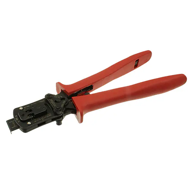
Hand Crimp Tool for Solder Right In-Board Terminals
Application Tooling
Specification Sheet
Modular Crimp Head
Order No. 63827-3070
TYPE 4A
Hand Crimp Tool
Order No. 63827-3000
FEATURES
%
%
%
%
%
%
A full cycle ratcheting hand tool ensures complete crimps
Ergonomically designed soft handles
Precisely designed crimping profiles with simple contact positioning
Easy handling due to outstanding force ratio
Modular Crimp Head is removable and can be use in the Air Powered Tool Order No.63816-0100,
accompanied by Air Powered Crimp Adapter (Order No. 63816-0700).
Can also be used in the Battery Powered Tool Order No.63816-0200 (110 V) or 63816-0250 (220 V),
accompanied by Battery Powered Crimp Adapter (Order No. 63816-0600).
SCOPE
Products: Solder Right In-Board Terminals, 14-16 AWG.
♦Insulation Diameter
UL1007 Wire is Recommended
Strip Length
IPC/WHMA-A620 (1) Terminal
AWG mm²
mm
In.
mm In.
mm
In.
172249
172249-0100
14-16
2.40-2.79 .094-.110 - 5.50-5.80 .216-.228
(1) To achieve optimum IPC-A620 Class 2 insulation crimps, use this insulation OD.
Terminal
Terminal Order No.
Series No.
Wire Size
DEFINITION OF TERMS
STRIP LENGTH
INSULATION CRIMP
BRUSH
BELL MOUTH
SEAM
WIRE
CONDUCTOR
CRIMP HEIGHT
Doc No: ATS-6382730HM
Revision: A
CUT-OFF TAB
Release Date: 08-14-14
Revision Date: 08-14-14
UNCONTROLLED COPY
Page 1 of 6
�Hand Crimp Tool for Solder Right In-Board Terminals
Crimp Specification
After crimping, the conductor profiles should measure the following (See Figure 1).
Terminal Series No.
172249
Conductor
Pull Force Minimum Profile
Crimp Height
Crimp Width
2
AWG mm
mm
In.
mm
In.
N
Lb.
A B
14
1.72-1.82 .068-.072 2.50-2.60 .098-.102
50
11.5
X
16
1.50-1.60 .059-.063 2.50-2.60 .098-.102
40
9.0
X
Seam: shall not be open and no wire allowed out of the crimping area.
Wire Size
Notes:
1. This tool should only be used for the terminals and wire gauges specified on this sheet.
2. This tool is not adjustable for crimp height. Variations in tools, terminals, wire stranding, and insulation types
may affect crimp height.
3. This tool is intended for AWG conductors with UL1007 insulation. It may not give a good insulation crimp
support for other insulation styles.
4. Molex does not repair hand tools (see Warranty on page 3). The replacement parts listed are the only parts
available for repair. If the handles or crimp tooling is damaged or worn, a new tool must be purchased.
5. Pull force should be used as the final criteria for an acceptable crimp. Refer to Molex Quality Crimping
Handbook 63800-0029 for additional information on crimping and crimp testing.
6. Molex does not certify crimp hand tools.
OPERATION
Open the tool by squeezing the handles together, at the end of the closing stroke, the
ratchet mechanism will release the handles, and the hand tool will spring open.
Figure 2
Preparing Terminals for Crimping
The terminals must be cut from the reel as shown. See Figure 2. The carrier strip hole is used to assist in loading
the terminal in position over the crimp anvils. The carrier strip will help maintain terminal position during crimping
and can be broken off after the crimp is complete.
Crimping Terminals
1. Load the terminal with carrier strip into the proper crimp profile.
Make sure the carrier strip pilot hole fits over the positioning pin.
2. Push the wire stop downward (into the tool frame).
3. Place the properly stripped wire into the open terminal barrel.
Push the wire into the tool until the end of the wire contacts the
wire stop, making sure that all wire strands are inside of the
conductor barrel. See Figures 3 and 4.
4. While holding the wire with one hand, slowly squeeze the tool
handles together to close the tool jaws until the ratchet
mechanism releases. At this point the handles can be released
and will spring open.
5. Remove the crimped terminal and inspect for acceptable crimp
attributes.
Note: The tamper proof ratchet action will not release the tool until it
has been fully closed.
Doc No: ATS-6382730HM
Revision: A
Release Date: 08-14-14
Revision Date: 08-14-14
WIRE STOP
PUSH DOWN
POSITIONING
PIN
LOCATOR
TERMINAL
CARRIER STRIP
UNCONTROLLED COPY
Figure 3
Page 2 of 6
�Hand Crimp Tool for Solder Right In-Board Terminals
Maintenance
It is recommended that each operator of the tool be made aware
of, and responsible for, the following maintenance steps:
CONDUCTOR
INSULATION
PUNCH
1. Remove dust, moisture, and other contaminants with a clean
PUNCH
brush, or soft, lint free cloth.
2. Do not use any abrasive materials that could damage the tool.
3. Make certain all pins; pivot points and bearing surfaces are
protected with a thin coat of high quality machine oil. Do not
WIRE STOP
WIRE
oil excessively. The tool was engineered for durability but like
any other equipment it needs cleaning and lubrication for a
maximum service life of trouble free crimping. Light oil (such
as 30 weight automotive oil) used at the oil points, every 5,000
TERMINAL
LOCATOR
crimps or 3 months, will significantly enhance the tool life.
RM
4. Wipe excess oil from hand tool, particularly from crimping
INSULATION
CONDUCTOR
area. Oil transferred from the crimping area onto certain
Figure 4
ANVIL
ANVIL
terminations may affect the electrical characteristics of an
application.
5. When tool is not in use, keep the handles closed to prevent objects from becoming lodged in the crimping dies,
and store the tool in a clean, dry area.
WIRE STOP
OPEN
CLAMP THE CARRIER
STRIP AND INSULATION
CRIMP GRIPS INTO THE
PULL TESTER
PULL TESTER
TERMINAL CLAMP
WIRE
PULL TESTER
WIRE CLAMP
Figure 5
WIRE IN CONDUCTOR CRIMP
Pull Test Procedure
Pull testing is to be done with no influence from the insulation crimp.
Figure 6
Pull testing can be done by the following steps:
1. Open the tool by squeezing the handles together, at the end of the closing stroke, the ratchet mechanism will
release the handles, and the hand tool will spring open.
2. Load the terminal with the carrier strip into the proper profile make sure the carrier strip pilot hole fits over the
positioning pin on the locator.
3. Do Not close the wire stop.
4. Position a wire form the back side of the Hand Tool and into the conductor crimp area only. See Figure 5.
5. Carefully crimp the terminal. Open the tool and remove the crimped terminal.
6. Flatten the crimped (empty) insulation grips. This area will be inserted and held in the pull tester grip.
7. Install crimped terminal into the pull tester as shown to perform the pull test. Be careful not to grip wire brush.
See Figure 6.
Doc No: ATS-6382730HM
Revision: A
Release Date: 08-14-14
Revision Date: 08-14-14
UNCONTROLLED COPY
Page 3 of 6
�Hand Crimp Tool for Solder Right In-Board Terminals
Miscrimps or Jams
Should this tool ever become stuck or jammed in a partially closed position, Do Not force the handles open or
closed. The tool will open easily by lifting the ratchet release lever. See Figure 6.
Warranty
This tool is for electrical terminal crimping purposes only. This tool is made of the best quality materials. All vital
components are long life tested. All tools are warranted to be free of manufacturing defects for a period of 30
days. Should such a defect occur, we will repair or exchange the tool free of charge. This repair or exchange will
not be applicable to altered, misused, or damaged tools. This tool is designed for hand use only. Any clamping,
fixturing, or use of handle extensions voids this warranty.
CAUTION: Repetitive use of this tool should be avoided.
CAUTIONS:
1. Manually powered hand tools are intended for low volume or field repair. This tool is NOT intended for
production use. Repetitive use of this tool should be avoided.
2. Insulated rubber handles are not protection against electrical shock.
3. Wear eye protection at all times.
4. Use only the Molex terminals specified for crimping with this tool.
CAUTION: Molex crimp specifications are valid only when used with Molex terminals and tooling.
Applications for the Modular Crimp Head
WARNING: NEVER operate, service, install, or adjust this Modular Crimp Head without proper instruction and
without first reading and understanding the instructions in the proper Manual or Specification Sheet. See Chart
below for the correct Manual or Specification Sheet.
WARNING: NEVER install tooling or service this tool while it is into any power source. Disconnect the power
by unplugging or turn off the Actuator from its power source.
CAUTION: Keep fingers away from the crimping area when operating this tool. It may cause severe injury.
CAUTION: Wear safety glasses when operating or serving this tool.
Doc No: ATS-6382730HM
Revision: A
Release Date: 08-14-14
Revision Date: 08-14-14
UNCONTROLLED COPY
Page 4 of 6
�Hand Crimp Tool for Solder Right In-Board Terminals
The chart below shows all applications for this Modular Crimp Head.
Modular Crimp Head
Order No.
63827-3070
Tool
Tool
Adapter
Adapter
Figure
Order no.
Description
Order No.
Description
No.
63816-0000 Hand Crimp Frame (Short)
N/A
N/A
3
63816-0050 Hand Crimp Frame (Long)
N/A
N/A
3
63816-0200 Battery Power Tool (110 V) 63816-0600 Battery Power Crimp Adapter
4
63816-0250 Battery Power Tool (220 V) 63816-0600 Battery Power Crimp Adapter
4
63816-0100
Air Power Tool
63816-0700
Air Power Crimp Adapter
5
Applications for the Modular Crimp Head
Hand Crimp Tool
Battery Powered Tool
MODULAR
CRIMP
HEAD
LOCKING
PINS
MODULAR
CRIMP
HEAD
LOCKING
PINS
HAND CRIMP
FRAME LONG
OR SHORT
Doc No: ATS-6382730HM
Revision: A
LOCKING
PINS
AIR POWER
CRIMP
ADAPTER
BATTERY
POWERED
TOOL
LOCKING
PINS
AIR
POWER
TOOL
Figure 4
Release Date: 08-14-14
Revision Date: 08-14-14
MODULAR
CRIMP HEAD
BATTERY
POWER
CRIMP
ADAPTER
LOCKING PINS
Figure 3
Air Powered Tool
UNCONTROLLED COPY
Figure 5
Page 5 of 6
�Hand Crimp Tool for Solder Right In-Board Terminals
PARTS LIST
Item Order Number
Description
Quantity
1
63827-3070
Modular Crimp Head
1 (Ref)
2
63816-0050
Hand Crimp Frame (Long) 1 (Ref)
3
63827-3075
Locator Plate
1
4
63816-0001
Locking Pin
2
5
63600-0525
Handle Spring
1
6
63600-0520
Crimping Spring
2
5
4
(2)
HANDLE
SPRING
2
RATCHET
RELEASE LEVER
M4 X 20mm
LONG BHCS
Figure 6
3
1
6
CRIMPING
SPRING (2)
Visit our Web site at http://www.molex.com
Doc No: ATS-6382730HM
Revision: A
Release Date: 08-14-14
Revision Date: 08-14-14
UNCONTROLLED COPY
Page 6 of 6
�
很抱歉,暂时无法提供与“0638273000”相匹配的价格&库存,您可以联系我们找货
免费人工找货- 国内价格 香港价格
- 1+5249.112101+679.05279
- 国内价格
- 1+5094.61472
- 3+4754.97853