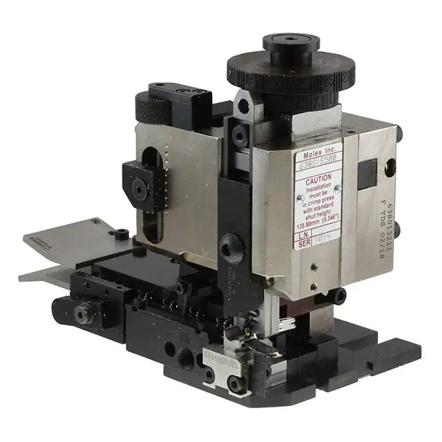
Mini-Mac Applicator for -“Mini-Fit Sr.” Terminals
Mini-Mac
Applicator
Application Tooling
Specification Sheet
Order No. 63891-9500
FEATURES
Directly adapts to most automatic wire processing machines. This applicator ships from the factory set-up in the
up-stroke condition for bench-top operation; however it will directly adapt to most automatic wire processing
machines. Please review the applicator manual that shipped with your tool and is linked on the Molex website.
Applicator designed to industry standard mounting and shut height 135.80mm (5.346")
Quick set-up time; plus the crimp height, track and feed adjustments can be set without removing the applicator
from the press
Fine adjustment allows users to achieve target with little effort by adjusting in increments of .015mm (.0006") for
conductor crimp height and .063mm (.0025") for insulation height
Independent adjustment rings allow users to quickly adjust the conductor or insulation crimp height without
affecting each other.
Optimum terminal feed/indexing can be obtained with the optional terminal guide assembly, Order No. 638300120. See page 6.
Easy change-over for terminal feeding (up-stroke or down-stroke). Applicator shipped as up-stroke.
SCOPE
Products: Mini-Fit Sr. ™ Male and Female Crimp Terminals, for fine stranded (2) 12 and 8 AWG wire.
Terminal
Series No.
Terminal Order No.
Wire Size
AWG
mm²
8
N/A
N/A
∗∗12
8
N/A
∗Insulation Diameter
mm
In.
5.00-6.75
.197-.266
3.50-4.00
.138-.157
5.00-6.75
.197-.266
Strip Length
mm
In.
9.00-10.00
.354-.394
11.00-12.00
.433-.472
9.00-10.00
.354-.394
42815-0030
42815-0031
42815-0032
42815-0134
42817-0030
42817-0130
42817-0031
42817-0131
42817
42817-0032
42817-0132
N/A
3.50-4.00
.138-.157
11.00-12.00
.433-.472
∗∗12
42817-1034
42817-1134
∗ On Mini-Fit Sr. 8 AWG terminal, the insulation is stripped in both the conductor and insulation grips.
∗∗ 8 AWG Hi-Flex wire (665 strands). This type of wire has very fine strands. Please note: Extra precaution must be maintained
during stripping operation to prevent loosing or breaking strands. Lost or broken strands may result in lower pull force strength and
broken strands may cause a possible electric shock or shortage.
1. Crimp terminals to stranded copper wire only.
2. Lubricate terminals plated in precious metals using Molex Oiler 63801-7240.
42815
Doc No: ATS-638919500
Revision: D
Release Date: 01-21-10
Revision Date: 09-21-16
UNCONTROLLED COPY
Page 1 of 7
�Mini-Mac Applicator for -“Mini-Fit Sr.” Terminals
DEFINITION OF TERMS
INSULATION
GRIP AREA
3.75mm ± 0.20
BELL MOUTH
3.75mm ± 0.20
WIRE INSULATION
CONTACT GAP
1.00mm ± 0.20
BEND
UP
SEAM
CONTACT GAP
0.00mm - 0.05mm
TWISTING
ROLLING
INSULATION GAP
0.00mm-1.00mm max.
BEND
DOWN
CRIMP SPECIFICATIONS
Terminal Series No.
42815
42817
Bell mouth
mm
In.
.20-.50 .008-.020
.20-.50 .008-.020
Terminal Series No.
Cut-off Tab Maximum
mm
In.
.30-.50
.012-.020
.30-.50
.012-.020
Bend up Bend down Twist Roll
Degree
Conductor Brush
mm
In.
2.10-3.10 .083-.122
2.10-3.10 .083-.122
Punch Width (Ref)
Conductor Insulation
mm In mm In
3.90 .154 4.80 .189
3.90 .154 4.80 .189
Degree
3
4
8
3
4
8
Seam
Seam shall not be open and no wire allowed out of the crimping area
42815
42817
3
3
After crimping, the conductor profile should measure the following.
Conductor
Pull Force
Minimum
Crimp Height
Crimp Width
AWG
mm2
mm
In.
mm
In.
N
Lb.
8
N/A
3.20-3.30
.126-.130
3.90
.154
400.3
90.0
42815
N/A
3.40-3.50
.134-.138
3.90
.154
400.3
90.0
∗∗ 8
(2) 12
N/A
3.20-3.30
.126-.130
3.90
.154
311.4
70.0
8
N/A
3.20-3.30
.126-.130
3.90
.154
400.3
90.0
42817
N/A
3.40-3.50
.134-.138
3.90
.154
400.3
90.0
∗∗ 8
(2) 12
N/A
3.20-3.30
.126-.130
3.90
.154
311.4
70.0
8
AWG
Hi-Flex
wire
(665
strands).
This
type
of
wire
has
very
fine
strands.
∗∗
Please note: Extra precaution must be maintained during stripping operation to prevent loosing or breaking strands.
Lost or broken strands may result in lower pull force strength and broken strands may cause a possible electric shock or shortage.
Terminal Series No.
Wire Size
Tool Qualification Notes:
1. Pull Force should be measured with no influence from the insulation crimp.
2. The above specifications are guidelines to an optimum crimp.
Doc No: ATS-638919500
Revision: D
Release Date: 01-21-10
Revision Date: 09-21-16
UNCONTROLLED COPY
Page 2 of 7
�Mini-Mac Applicator for -“Mini-Fit Sr.” Terminals
Special Note:
1. Cut-off Tab length below 0.30mm may cause the box dimension to be under recommendation. See Figure 1.
2. Wire insulation should not be crimped and insulation grip area should be formed to contain wire strands only.
3. Changing the insulation height setting may be needed to achieve the dimensions of the insulation grip in
Section A-A. See Figure 1.
4. If wire strands are missed from conductor crimps, the operator should place the wires in the terminal, in the
correct location, without using the wire stop/ stripper for locating the wire.
EXTRUDED WIRE LENGTH
(BRUSH)
BELL MOUTH (FLARE)
0.50mm
REF
INSULATION GRIP
A
5.00mm
REF
A
Figure 1
WIRE STRANDS
CUT-OFF TAB LENGTH
SECTION A-A
Doc No: ATS-638919500
Revision: D
Release Date: 01-21-10
Revision Date: 09-21-16
UNCONTROLLED COPY
Page 3 of 7
�Mini-Mac Applicator for -“Mini-Fit Sr.” Terminals
PARTS LIST
Mini-Mac Applicator 63891-9500
Item
Order No
Engineering No.
Description
Quantity
Perishable Tooling
63891-9570
63891-9570
Tool Kit (All “Y” Items)
REF
1
63830-0001
63830-0001
Conductor Punch
1Y
2
63830-0002
63830-0002
Conductor Anvil
1Y
3
63830-0003
63830-0003
Insulation Punch
1Y
4
63830-0004
63830-0004
Insulation Anvil
1Y
5
63443-0037
63443-0037
Front Cut-off Plunger
1Y
6
63443-0038
63443-0038
Front Cut-off Plunger Retainer
1Y
Plunger Retainer (Non Carrier Cut-Off)
6
63443-4204
63443-4204
0
To be used on all wire processors only.
Other Components
7
11-18-4848
60800A123
Spring Retainer
1
8
11-18-4849
60800A124
Wire Hold Down Spring
1
9
63443-0009
63443-0009
Scrap Chute Front
1
10
63443-0024
63443-0024
Lower Tooling Key
1
11
63443-1715
63443-1715
Height Spacer
1
12
63443-2209
63443-2209
Course Spacer (9.00mm)
1
13
63443-2306
63443-2306
Fine Spacer (3.30mm)
1
14
63466-0504
63466-0504
Front Plunger Striker
1
15
63700-0539
63700-0539
Cut-Off Plunger Spring
1
16
63803-5105
63803-5105
Conductor Bushing
1
17
63803-5201
63803-5201
Insulation Bushing
1
18
63821-0012
63821-0012
Front Cover
1
19
63821-0015
63821-0015
Wire Stop
1
20
63830-0117
63830-0117
Terminal Lead In
2
21
63830-0118
63830-0118
Rear Cover
1
Frame
22
63801-3201
63801-3201
Top
1
23
63801-3281
63801-3281
Base
1
24
63801-4650
63801-4650
Track
1
Hardware
25
N/A
N/A
M3 by 6 Long FHCS
1**
26
N/A
N/A
M3 by 6 Long SHCS
2**
27
N/A
N/A
M4 by 6 Long SHCS
5**
28
N/A
N/A
M4 by 12 Long BHCS
2**
29
N/A
N/A
M4 by 50 Long SHCS
2**
30
N/A
N/A
M5 by 12 Long SHCS
1**
31
N/A
N/A
M8 by 25 Long BHCS
1**
32
N/A
N/A
2mm by 5 Long Roll Pin
1**
** Fastener parts can be obtained through most industrial supply houses by using the generic
descriptions listed above in the parts list table.
Abbreviation descriptions: SHCS = Socked Head Cap Screw, FHCS = Flat Head Cap Screw,
SSS = Socket Set Screw, BHCP = Button Head Cap Screw, Roll Pin = Spiral Pin.
Doc No: ATS-638919500
Revision: D
Release Date: 01-21-10
Revision Date: 09-21-16
UNCONTROLLED COPY
Page 4 of 7
�Mini-Mac Applicator for -“Mini-Fit Sr.” Terminals
Assembly Drawing
22
1
16
3
7
14
27
(4)
31
17
8
28
(2)
22
20 (2)
24
21
23
(2)
19
26
30
18
2
5
4
12
32
15
13
11
10
25
6
(2)
29
Doc No: ATS-638919500
Revision: D
9
Figure 2
27
Release Date: 01-21-10
Revision Date: 09-21-16
UNCONTROLLED COPY
Page 5 of 7
�Mini-Mac Applicator for -“Mini-Fit Sr.” Terminals
Older Version Applicators
Older versions of this applicator can be updated with the Terminal Guide Assembly please order the parts below.
The Terminal Guide Assembly helps to align slightly bent up or down terminals, entering the track.
Recommended for use with wire processing equipment, or roughly handled terminal reels. To install the Terminal
Guide assembly follow the steps below.
1.
2.
3.
4.
Remove the (2) M4 by 12 BHCS from the existing rear cover.
Remove the rear cover
Replace it with the 63830-0120 Terminal Guide Assembly.
Replace the (2) M4 by 12 BHCS.
1
3
(4)
M4 by 12.0mm LONG
BHCS (2) REFERNCE
2
1
Terminal Guide Assembly 63830-0120
Item
Order No
Engineering No.
Description
Quantity
1
63830-0117
63830-0117
Terminal Lead-In
2
2
63830-0118
63830-0118
Rear Cover
1
Hardware
3
N/A
N/A
M4 by 6 Long SHCS
4**
** Fastener parts can be obtained through most industrial supply houses by using the
generic descriptions listed above in the parts list table.
Abbreviation descriptions: SHCS = Socked Head Cap Screw, FHCS = Flat Head Cap
Screw, SSS = Socket Set Screw, BHCP = Button Head Cap Screw, Roll Pin = Spiral Pin.
Doc No: ATS-638919500
Revision: D
Release Date: 01-21-10
Revision Date: 09-21-16
UNCONTROLLED COPY
Page 6 of 7
�Mini-Mac Applicator for -“Mini-Fit Sr.” Terminals
NOTES
1. Molex recommends an extra perishable tooling kit be maintained at your facility.
2. Verify tooling alignment by manually cycling the press and applicator before crimping under power. Check that all
screws are tight.
3. Slugs, terminals, dirt, and oil should be kept clear of work area.
4. Wear safety glasses at all times.
5. For recommended maintenance refer to the Mini-Mac Manual.
This applicator should only be used in a press with a shut height of 135.80 mm (5.346”).
Tooling damage could result at a lower setting
CAUTION
CAUTION
CAUTION
To prevent injury, never operate this applicator without the guards supplied with the press or
wire-processing machine in place. Reference the press or wire processing manufacturer’s
instruction manual.
Molex tooling crimp specifications are valid only when used with Molex terminals and tooling
manufactured by Molex or authorized distributors (“Molex Tooling”). When using tooling
other than Molex Tooling with specific Molex specific connector systems listed in our ATS
documents, the Molex tooling qualification does not apply and the responsibility for full
qualification of the connector system is that of the customer.
Molex accepts no liability for connector performance or tooling support where tooling other
than Molex Tooling is used, or where Molex Tooling is modified.
A-620 and other industry standards do not supersede the manufacturer’s specifications.
Some terminals designed over 20 years ago may not meet the desired physical attributes for
some of today’s standards. However, these terminals will still perform electrically at an
acceptable quality level based on the qualification testing and years of successful
performance in the field.
Contact Information
Application Tooling Support
2200 Wellington Court
Lisle, IL 60532 USA
Direct +1-402-458-TOOL (8665)
Visit our website at www.molex.com/applicationtooling
Doc No: ATS-638919500
Revision: D
Release Date: 01-21-10
Revision Date: 09-21-16
UNCONTROLLED COPY
Page 7 of 7
�
很抱歉,暂时无法提供与“0638919500”相匹配的价格&库存,您可以联系我们找货
免费人工找货