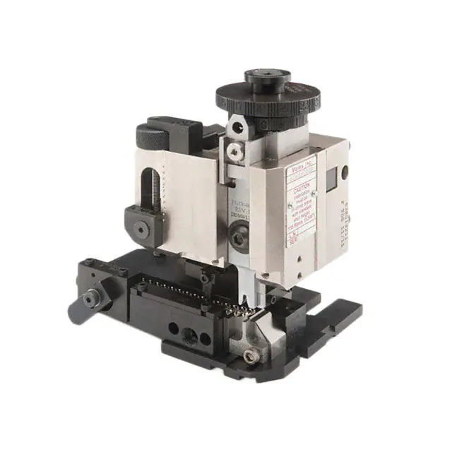
Fine Adjust Applicator for SL™ Crimp Terminal
FineAdjust
Applicator
Application Tooling
Specification Sheet
Order No. 63902-7800
FEATURES
Quick punch removal with the push of a button for fast and easy tooling change
Applicator designed to industry standard mounting and shut height 135.80mm (5.346")
Quick set-up time; plus the crimp height, track and feed adjustments can be set without removing the applicator
from the press
Fine adjustment allows users to achieve target with little effort by adjusting in increments of .015mm (.0006") for
conductor crimp height and .063mm (.0025") for insulation height
Independent adjustment rings allow users to quickly adjust the conductor or insulation crimp height without
affecting each other
Directly adapts to most automatic wire processing machines
SCOPE
Products: SL™ Crimp Terminal, Male, 22-24 AWG.
Terminal
Series No.
50088
70021
(1)
(2)
Terminal Order No.
Wire Size
Insulation Diameter
IPC/WHMA-A620 (1)
Terminal (2)
mm
In.
mm
In.
Strip Length
AWG
mm²
mm
In.
50088-8000 50088-8060
50088-8014 50088-8099
22-24 0.35-0.20 1.25-1.45 .049-.057 1.00-1.60 .039-.063 3.00-3.50 .118-.138
50088-8028
16-02-0081 16-02-0116 70021-0021
16-02-0093 40-08-0874 70021-0023 22-24 0.35-0.20 1.25-1.45 .049-.057 1.40-1.63 .055-.064 3.17-3.56 .125-.140
16-02-0107 70021-0019 70021-0081
To achieve optimum IPC-A620 Class 2 insulation crimp, use this insulation diameter
Overall insulation diameter specification for terminal
DEFINITION OF TERMS
BEND UP
REAR
CUT-OFF TAB
ROLLING
STRIP LENGTH
BELL MOUTH
CONDUCTOR BRUSH
TWISTING
BEND
DOWN
CONDUCTOR
CRIMP HEIGHT
SEAM
FRONT
CUT-OFF TAB
INSULATION
CRIMP
Doc No: ATS-639027800
Revision: A
Release Date: 01-20-14
Revision Date: 01-20-14
UNCONTROLLED COPY
Page 1 of 5
�Fine Adjust Applicator for SL™ Crimp Terminal
CRIMP SPECIFICATION
Bell mouth
Terminal Series No.
mm
0.20-0.50
0.20-0.50
50088
70021
In.
.008-.020
.008-.020
Bend up Bend down
Terminal Series No.
50088
70021
Twist
Degree
3
3
Cut-off Tab Maximum
Front
Rear
mm
In.
mm
In.
0.15 .006 0.30 .012
0.13 .005 0.13 .005
Roll
Degree
3
3
3
3
8
8
Conductor Brush
mm
0.00-1.00
0.00-1.00
Punch Width mm (Ref)
Conductor Insulation
mm
In
mm
In
1.40 .055 1.70 .067
1.40 .055 1.70 .067
In.
.000-.039
.000-.039
Seam
Seam shall not be open
and no wire allowed out
of the crimping area
After crimping, the conductor profile should measure the following.
Terminal Series No.
50088
70021
Wire Size
AWG mm2
22
0.35
24
0.20
22
0.35
24
0.20
Crimp Height
mm
In.
0.84-0.89 .032-.035
0.74-0.81 .029-.032
0.84-0.89 .032-.035
0.74-0.81 .029-.032
Pull Force Minimum
N
Lb.
39.1
8.8
29.3
6.6
35.6
8.0
22.2
5.0
Tool Qualification Notes:
1. Pull Force should be measured with no influence from the insulation crimp.
2. The above specifications are guidelines to an optimum crimp.
Doc No: ATS-639027800
Revision: A
Release Date: 01-20-14
Revision Date: 01-20-14
UNCONTROLLED COPY
Page 2 of 5
�Fine Adjust Applicator for SL™ Crimp Terminal
PARTS LIST
Item
1
2
3
4
5
6
7
8
9
10
11
12
13
14
15
16
17
18
19
20
21
22
23
24
25
26
27
28
29
30
31
32
33
34
35
FineAdjust Applicator 63902-7800
Engineering No.
Description
Quantity
Perishable Tooling
63902-7870
63902-7870
Tool Kit (All “Y” Items)
REF
63444-1417
63444-1417
Conductor Punch
1Y
63445-1446
63445-1446
Conductor Anvil
1Y
63454-0123
63454-0123
Insulation Punch
1Y
63445-1730
63445-1730
Insulation Anvil
1Y
63443-0003
63443-0003
Cut-Off Plunger
1Y
63443-0012
63443-0012
Front Plunger Retainer
1Y
63443-1401
63443-1401
Cut-off Die Blade
1Y
63466-0201
63466-0201
Rear Cut-Off Plunger
1Y
63466-0301
63466-0301
Rear Plunger Retainer
1Y
Other Components
11-18-4083
60707-8
Feed Guide
1
11-24-1067
4996-4
Cut-Off Plunger Spring
2
63443-0009
63443-0009
Scrape Chute
1
63443-0024
63443-0024
Key
1
63443-0090
63443-0090
Wire Stop
1
63443-1720
63443-1720
Height Spacer
1
63443-2204
63443-2204
Coarse Spacer (4.00mm)
1
63443-2310
63443-2310
Fine Spacer(3.50mm)
1
63443-2802
63443-2802
Plunger Striker
1
63443-2907
63443-2907
Plunger
1
63443-3060
63443-3060
Rear Plunger Striker
1
63443-6111
63443-6111
Rear Cover
1
63600-1057
63600-1057
Compression Spring
1
Frame
63800-4901
63800-4901
Top
1
63801-3281
63801-3281
Base
1
63801-4650
63801-4650
Track
1
Hardware
N/A
N/A
M3 by 6 Long SHCS
2**
N/A
N/A
M3 by 6 Long FHCS
1**
N/A
N/A
M4 by 6 Long SHCS
2**
N/A
N/A
M4 by 8 Long SHCS
1**
N/A
N/A
M4 by 10 Long SHCS
2**
N/A
N/A
M4 by 12 Long BHCS
2**
N/A
N/A
M4 by 50 Long SHCS
2**
N/A
N/A
M5 by 12 Long SHCS
1**
N/A
N/A
#10-32 by 3/8”Long Flat Point SSS
1**
N/A
N/A
#10-32 Hex Jam Nut
1**
** Available from an industrial supply company such as MSC (1-800-645-7270).
Doc No: ATS-639027800
Revision: A
Order No
Release Date: 01-20-14
Revision Date: 01-20-14
UNCONTROLLED COPY
Page 3 of 5
�Fine Adjust Applicator for SL™ Crimp Terminal
Assembly Drawing
23
34
35
1
22
31 (2)
20
18
30
(2)
21
3
19
(2)
26
23
25
5
10
(2)
11
24
14
6
(2)
12
33
8
7
28
17
28
32
(2)
2
9
29
14
16
15
Figure 1
13
4
27
Doc No: ATS-639027800
Revision: A
Release Date: 01-20-14
Revision Date: 01-20-14
UNCONTROLLED COPY
Page 4 of 5
�Fine Adjust Applicator for SL™ Crimp Terminal
NOTES
1. Molex recommends an extra perishable tooling kit be maintained at your facility.
2. Verify tooling alignment by manually cycling the press and Applicator before crimping under power. Check
that all screws are tight.
3. Slugs, Terminals, Dirt and Oil should be kept clear of work area.
4. Wear safety glasses at all times.
5. For recommended maintenance refer to the FineAdjust Manual.
CAUTION: This applicator should only be used in a press with a shut height of 135.80 mm (5.346”). Tooling
damage could result at a lower setting.
CAUTION: To prevent injury never operate this Applicator without the guards supplied with the press or wireprocessing machine in place. Reference the press or wire processing manufacturer’s instruction manual.
CAUTION: Molex crimp specifications are valid only when used with Molex terminals, applicators and tooling.
Visit our Web site at http://www.molex.com
Doc No: ATS-639027800
Revision: A
Release Date: 01-20-14
Revision Date: 01-20-14
UNCONTROLLED COPY
Page 5 of 5
�
很抱歉,暂时无法提供与“0639027800”相匹配的价格&库存,您可以联系我们找货
免费人工找货- 国内价格 香港价格
- 1+47208.026931+6093.62368