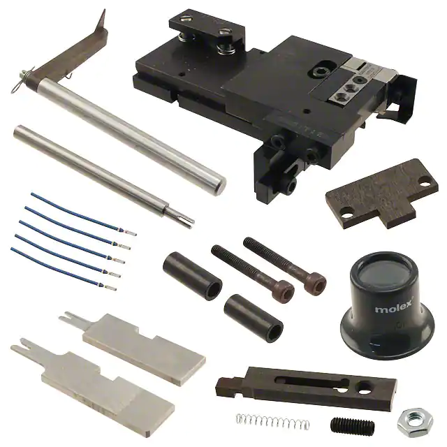
T2 Terminator for 3.7 LED Connector Plug Crimp Terminal
T2 Terminator Tooling
Specification Sheet
Order No. 63911-9500
FEATURES
�
�
�
�
�
It is ideally suited for mid-volume bench operations
This terminator can be installed in the TM42 and the TM40 press or Base Unit adapter for 3BF press
Quick punch removal with the push of a button for fast and easy tooling change
Track adjustment capabilities in the T2 Terminators for improved control of the bell mouth size and cutoff tab
length
T2 Terminator has standardized tooling with the Molex FineAdjust Applicator which will reduce your inventory
requirements
SCOPE
Products: 3.7 LED Connector Plug Crimp Terminal, 26-28 AWG.
Terminal
Series No.
503485
Terminal
Order No.
Insulation Diameter
IPC/WHMA-A620�
Terminal��
mm
In.
mm
In.
Wire Size
AWG
mm²
Strip Length
mm
In.
503485-0000 26-28 .141-.079 0.93-1.14 .037-.045 0.93-1.14 .037-.045 1.30-1.50 .051-.059
�To achieve optimum IPC-A620 insulation crimps, use this insulation OD range.
��Overall insulation OD specification for terminal.
DEFINITION OF TERMS
BEND UP
BRUSH
BELL
MOUTH
CONDUCTOR
CRIMP
ROLLING
SEAM
INSULATION
CRIMP
TWISTING
STRIP
LENGTH
BEND
DOWN
CUT-OFF
TAB
CRIMP HEIGHT
The above terminal drawing is a generic terminal representation. It is not an image of a terminal listed in the
scope.
Doc No: ATS-639119500
Revision: A
Release Date: 06-07-10
Revision Date: 06-07-10
UNCONTROLLED COPY
Page 1 of 6
�T2 Terminator for 3.7 LED Connector Plug Crimp Terminal
CRIMP SPECIFICATION
Bell mouth
Mm
In.
0.10-0.30 .004-.012
Terminal Series No.
503485
Terminal Series No.
Bend up Bend down Twist
Degree
503485
3
Cut-off Tab Maximum
mm
In.
0.15
.006
Roll
Degree
3
6
3
Conductor Brush
mm
In.
0.10-0.40 .004-.016
Punch Width mm (Ref)
Seam
Conductor Insulation Seam shall not be open
mm In mm In and no wire allowed out
of the crimping area
0.80 .031 1.30 .051
After crimping, the conductor profile should measure the following.
Wire Size
Terminal
Series No. AWG mm2
503485
26
28
Conductor Crimp
Pull Force
Crimp Height
Crimp Width (Ref.) Minimum
mm
In.
mm
In.
N
Lb.
0.14 0.56-0.61 .022-.024
0.85
.033
9.80 2.20
0.08 0.53-0.58 .021-.023
0.85
.033
9.80 2.20
Wire Size
Terminal
Ordr No. AWG mm2
503485
26
28
0.14
0.08
Insulation
Crimp Width
(Ref.)
In.
mm
In.
.051-.059 1.35
.053
.051-.059 1.35
.053
Crimp Height
mm
1.30-1.50
1.30-1.50
Pull Force should be measured with no influence from the insulation crimp.
The above specifications are guidelines to an optimum crimp.
Doc No: ATS-639119500
Revision: A
Release Date: 06-07-10
Revision Date: 06-07-10
UNCONTROLLED COPY
Page 2 of 6
�T2 Terminator for 3.7 LED Connector Plug Crimp Terminal
PARTS LIST
T2 Terminator 63911-9500
Item Order No Engineering No.
Description
Quantity
Perishable Tooling
63911-9570
63911-9570
Tool Kit (All “Y” Items)
REF
63457-0072
63457-0072
Conductor Punch
1Y
1
63455-0099
63455-0099
Conductor Anvil
1Y
2
63454-0119
63454-0119
Insulation Punch
1Y
3
63456-0082
63456-0082
Insulation Anvil
1Y
4
5
63443-0005
63443-0005
Front Cut-Off Plunger
1Y
6
63443-0012
63443-0012
Front Plunger Retainer
1Y
Other Components
7
11-18-4083
60707-8
Feed Guide
1
8
11-24-1067
4996-4
Cut-Off Plunger Spring
1
9
63443-0009
63443-0009
Front Scrap Chute
1
10
63443-0024
63443-0024
Key
1
11
63443-0085
63443-0085
Wire Stop L-Bracket
1
12
63443-0090
63443-0090
Wire Stop
1
63443-2201
63443-2201
1.00mm Coarse Spacer
1
13
63443-2216
63443-2216
16.00mm Coarse Spacer
1
14
63443-2312
63443-2312
3.60mm Fine Spacer
1
15
16
63443-2805
63443-2805
Front Plunger Striker
1
17
63443-2905
63443-2905
Wire Hold Down Plunger
1
18
63443-6001
63443-6001
Rear Cover
1
19
63443-7201
63443-7201
Spring Cover
1
20
63600-0021
63600-0021
Wire Hold Down Spring
1
21
63600-2972
63600-2972
Collar
2
63890-0093
63890-0093
Height Spacer
1
22
Frame
23
63800-8500
63800-8500
T2 Terminator
1
Hardware
24
N/A
N/A
M3 by 6 Long SHCS
2**
25
N/A
N/A
M3 by 6 Long FHCS
1**
26
N/A
N/A
M4 by 6 Long SHCS
2**
27
N/A
N/A
M4 by 12 Long BHCS
2**
28
N/A
N/A
M4 by 14 Long SHCS
2**
29
N/A
N/A
M4 by 30 Long SHCS
2**
30
N/A
N/A
M4 by 50 Long SHCS
2**
31
N/A
N/A
M5 by 12 Long SHCS
1**
32
N/A
N/A
#10-32 by 3/8”Long BHCS
1**
** Available from an industrial supply company such as MSC (1-800-645-7270).
Doc No: ATS-639119500
Revision: A
Release Date: 06-07-10
Revision Date: 06-07-10
UNCONTROLLED COPY
Page 3 of 6
�T2 Terminator for 3.7 LED Connector Plug Crimp Terminal
Assembly Drawing
1
3
20
16
32
21
(2)
19
27 (2)
17
2
5
24
8
29
(2)
18
(2)
11
6
7
28
4
9
30
(2)
12
31
26
(2)
13
23
14
12
26
15
Figure 1
22
10
25
Doc No: ATS-639119500
Revision: A
Release Date: 06-07-10
Revision Date: 06-07-10
UNCONTROLLED COPY
Page 4 of 6
�T2 Terminator for 3.7 LED Connector Plug Crimp Terminal
NOTES
Depending on the press vintage a feed finger assembly is supplied with the T2 Terminator.
1.
2.
3.
4.
To remove the existing feed finger assembly loosens the M4 x 10 mm set screw in the feed lever.
Select T2 Feed finger assembly from Terminator box.
Insert a screwdriver into the slot behind the feed lever and force the feed arm spring to the right.
Slide the T2 feed finger shaft for TM42 (11-40-5307) or (11-40-0123) for TM40 /Base Unit into the feed lever
and to the left of the feed arm spring.
5. Release the feed arm spring.
6. Position feed finger for selected product. (Refer to Figure 5.1 in the T2 Manual).
TM40 PRESS AND
BASE UNIT AND ADAPTER
TM42 PRESS
11-40-0123
FEED FINGER ROD
11-40-5307
FEED FINGER ROD
COTTER PIN
1/8” X .0295 DIA. WIRE
COTTER PIN
1/8” X .0295 DIA. WIRE
11-40-5255
FEED FINGER
11-40-5255
FEED FINGER
11-40-0125
FEED ARM SPRING
11-40-0125
FEED ARM SPRING
FEED FINGER ASSEMBLY
FOR PRESS TM42
FEED FINGER ASSEMBLY
FOR PRESS TM40
Figure 2
Doc No: ATS-639119500
Revision: A
Release Date: 06-07-10
Revision Date: 06-07-10
UNCONTROLLED COPY
Page 5 of 6
�T2 Terminator for 3.7 LED Connector Plug Crimp Terminal
NOTES
1. Molex recommends an extra perishable tooling kit be maintained at your facility.
2. Verify tooling alignment by manually cycling the press before crimping under power. Check that all screws are
tight.
3. Slugs, Terminals, Dirt and Oil should be kept clear of work area.
4. This Terminator should be only used in a Molex TM42, TM40, or 3BF Press with a Base Unit adaptor.
5. Wear safety glasses at all times.
6. For recommended maintenance refer to the TM40, TM42 Manual.
CAUTION: To prevent injury never operate this Terminator without the guards supplied with the press or in
place. Reference the TM42 press manufacturer’s instruction manual.
CAUTION: Molex crimp specifications are valid only when used with Molex terminals, applicators and
tooling.
http://www.molex.com
Doc No: ATS-639119500
Revision: A
Release Date: 06-07-10
Revision Date: 06-07-10
UNCONTROLLED COPY
Page 6 of 6
�
很抱歉,暂时无法提供与“0639119500”相匹配的价格&库存,您可以联系我们找货
免费人工找货