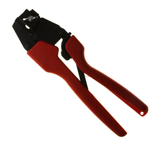
RHT 2200 Hand Crimp Tool
Hand Crimp Tool Operating Instruction
And Specifications Sheet
Order No. 64001-1500
Eng. No. RHT 2200
(Replaces 19285-0018)
FEATURES
A full cycle ratcheting hand tool ensures complete crimps
Long handles for comfortable crimping with reduced crimping force
A precision user-friendly terminal locator wire stop holds terminals in the proper crimping position
Insulation crimp adjustment allows a precise insulation crimp. To meet or exceed the requirements
of UL, CSA and Military Class II
Single color-coded crimp pocket eliminates the possibility of using the wrong pocket
SCOPE
AviKrimp and InsulKrimpTerminals and Splices 10-12 AWG, (Rings, Spades, Hooks, Snap
Spades and Flanged Spades, Wire Pin Terminals and also 3 to 4 way connectors). Also terminates ends
of step down butt splice 10-12 to 14-16 AWG.
Testing
Mechanical
Wire Size (AWG)
*UL - 486 A *UL – 486 C
The tensile test, or pull test, is a means of evaluating
16
N/A
15
the mechanical properties of the crimped connections.
14
N/A
25
12
70
35
The following charts show the UL specifications for
10
80
40
various wire sizes. The tensile strength is shown in
pounds and indicates the minimum acceptable force to break or separate the terminal from the
conductor.
*UL - 486 A - Terminals (Copper
conductors only)
*UL - 486 C - Butt Splices
The following is a partial list of the product part numbers and their specifications that this tool is
designed to run. We will be adding to this list and an up to date copy is available on www.molex.com.
Terminal No.
19070-0119
19070-0121
19070-0123
19070-0130
19070-0132
19070-0136
19070-0143
19070-0145
19070-0150
19070-0153
19070-0155
19073-0145
19073-0147
19073-0160
19073-0163
Wire Size: 10 – 12 AWG 5.00 – 3.00 mm²
Terminal
Wire Strip Length Insul. Dia. Max.
Eng No. (REF)
In
mm
In
mm
C-228-06X
.375
9.53
250
6.35
C-228-08X
.375
9.53
.250
6.35
C-228-10X
.375
9.53
.250
6.35
C-230-10X
.375
9.53
.250
6.35
C-230-14X
.375
9.53
.250
6.35
C-230-56X
.375
9.53
.250
6.35
C-236-06X
.375
9.53
.250
6.35
C-236-08X
.375
9.53
.250
6.35
C-240-14X
.375
9.53
.250
6.35
C-240-38X
.375
9.53
.250
6.35
C-240-56X
.375
9.53
.250
6.35
C-801-12
.375
9.53
.225
5.72
C-801-12X
.375
9.53
.250
6.35
C-828-06
.375
9.53
.225
5.72
C-828-06X
.375
9.53
.250
6.35
Doc No. 64001-1500 Release Date: 01-15-03
Revision: C
Revision Date: 01-10-06
Terminal No.
19073-0165
19073-0168
19073-0170
19073-0173
19073-0179
19073-0181
19073-0182
19073-0185
19073-0188
19073-0191
19073-0192
19073-0195
19073-0200
19073-0202
19073-0203
Wire Size: 10 – 12 AWG 5.00 – 3.00 mm²
Terminal
Wire Strip Length Insul. Dia. Max.
Eng No. (REF)
In
mm
In
mm
C-828-08
.375
9.53
.225
5.72
C-828-08X
.375
9.53
.250
6.35
C-828-10
.375
9.53
.225
5.72
C-828-10X
.375
9.53
.250
6.35
C-830-10
.375
9.53
.225
5.72
C-830-10X
.375
9.53
.250
6.35
C-830-10XLBK
.375
9.53
.225
5.92
C-830-10XX
.375
9.53
.320
8.13
C-830-14
.375
9.53
.225
5.72
C-830-14X
.375
9.53
.250
6.35
C-830-14XLBK
.375
9.53
.225
5.92
C-830-14XX
.375
9.53
.320
8.13
C-830-56
.375
9.53
.225
5.72
C-830-56X
.375
9.53
.250
6.35
C-830-56XLBK
.375
9.53
.225
5.92
UNCONTROLLED COPY
Page 1 of 7
�RHT 2200 Hand Crimp Tool
Terminal No.
19073-0206
19073-0216
19073-0220
19073-0222
19073-0225
19073-0227
19073-0229
19073-0231
19073-0233
19073-0236
19073-0238
19073-0242
19073-0244
19073-0272
19073-0273
19073-0274
19081-0005
19090-0083
19090-0085
19099-0044
19099-0048
19099-0050
19115-0033
19115-0035
19115-0037
19115-0039
19115-0041
19115-0042
19115-0046
19115-0048
19127-0086
Wire Size: 10 – 12 AWG 5.00 – 3.00 mm²
Terminal
Wire Strip Length Insul. Dia. Max.
Eng No. (REF)
In
mm
In
mm
C-830-56XX
.375
9.53
.320
8.13
C-836-06
.375
9.53
.225
5.72
C-836-06X
.375
9.53
.250
6.35
C-836-08
.375
9.53
.225
5.72
C-836-08X
.375
9.53
.250
6.35
C-840-10
.375
9.53
.225
5.72
C-840-10X
.375
9.53
.250
6.35
C-840-14
.375
9.53
.225
5.72
C-840-14X
.375
9.53
.250
6.35
C-840-38
.375
9.53
.225
5.72
C-840-38X
.375
9.53
.250
6.35
C-840-56
.375
9.53
.225
5.72
C-840-56X
.375
9.53
.250
6.35
C-830-10XXBK
.375
9.53
.320
8.13
C-830-14XXBK
.375
9.53
.320
8.13
C-830-56XXBK
.375
9.53
.320
8.13
C-5006-MS
.375
9.53
.225
5.72
C-212-08X
.375
9.53
.250
6.35
C-212-10X
.375
9.53
.250
6.35
C-2710-06X
.375
9.53
.225
5.72
C-2718-08X
.375
9.53
.225
5.72
C-2719-10X
.375
9.53
.225
5.72
C-8196-06
.375
9.53
.225
5.72
C-8197-08
.375
9.53
.225
5.72
C-8198-10
.375
9.53
.225
5.72
C-8199-14
.375
9.53
.225
5.72
C-8710-05
.375
9.53
.225
5.72
C-8710-06
.375
9.53
.225
5.72
C-8718-08
.375
9.53
.225
5.72
C-8719-10
.375
9.53
.225
5.72
C-817-08
.375
9.53
.225
5.72
Terminal No.
19127-0089
19139-0060
19144-0037
19144-0039
19144-0042
19144-0046
19154-0028
19154-0037
19183-0019
19198-0039
19198-0044
19198-0047
19198-0050
19198-0056
19198-0057
19204-0025
19204-0026
19204-0029
19204-0030
19206-0010
19212-0001
19213-0007
Terminal No.
19154-0035
Wire Size: 10 – 12 AWG 5.00 – 3.00 mm²
Terminal
Wire Strip Length Insul. Dia. Max.
Eng No. (REF)
In
mm
In
mm
C-817-10
.375
9.53
.225
5.72
C-8105-08
.375
9.53
.225
5.72
C-241-06X
.375
9.53
.250
6.35
C-241-08X
.375
9.53
.250
6.35
C-241-10X
.375
9.53
.250
6.35
C-268-14X
.375
9.53
.250
6.35
C-246X
.225
5.95
.225
5.72
CS-V-346X
.281
7.14
.225
5.72
C-811-10
.375
9.53
.225
5.72
C-8105-06
.375
9.53
.225
5.72
C-841-06
.375
9.53
.225
5.72
C-841-08
.375
9.53
.225
5.72
C-841-10
.375
9.53
.225
5.72
C-868-14
.375
9.53
.225
5.72
C-868-14X
.281
7.14
.250
6.35
C-2XCX
.375
9.53
.225
5.72
C-2YCX
.375
9.53
.225
5.72
C-5XC
.375
9.53
.225
5.72
C-5YC
.375
9.53
.225
5.72
CS-V-303X
.281
7.14
.260
6.60
WP-2210X
.281
7.14
.250
6.35
WP-8210
.281
7.14
.225
5.72
STEP DOWN BUTT SPLICE
Wire Size: 10 – 12 AWG 5.00 – 3.00 mm²
to 14 -16 AWG 2.00-1.30 mm²
Terminal
Wire Strip Length
Insul. Dia. Max.
Eng No. (REF)
In
mm
In
mm
CB-646X
.281
7.14
.260
6.60
JAWS OPEN
OPERATION
Open the tool by first closing the jaws sufficiently for the
ratchet mechanism to release.
TERMINAL
Crimping Terminals
1. Push up on the locator blade and position the terminal
with the barrel facing up into the color-coded nest
with front edge of the barrel against the locator (See
Figure 1). Release the locator blade to hold the
terminal in position.
2. Partially close the tool to hold the terminal in place
(See Figure 2).
3. Insert the properly stripped wire into the terminal
barrel (See Figure 2 and 3). The wires end should
butt against the wire stop position of the locator.
Cycle the tool.
FRONT
EDGE OF
BARREL
LOCATOR
Figure 1
PUSH UP
Note: The tamper proof ratchet action will not release the tool until it has been fully closed.
Doc No. 64001-1500 Release Date: 01-15-03
Revision: C
Revision Date: 01-10-06
UNCONTROLLED COPY
Page 2 of 7
�RHT 2200 Hand Crimp Tool
4. Lift the locator blade or wire stop and remove the crimped
terminal. Inspect for proper crimp location, and check for
insulation closure. Locator is adjustable up and down to keep
terminals straight after crimping.
5. If the insulation part of the crimp needs to be adjusted, first
loosen the M4 screw on the bottom tool jaw, then insert a 3/32
hex wrench (supplied) into the bottom of the lower die (See
Figure 5). A clockwise (CW) rotation decreases insulation crimp
while a counter-clockwise (CCW) rotation increases insulation
crimp. After adjusting retighten the M4 screw.
6. When crimping butt splices, or 3-way and 4-way terminals the
locator must be removed. Splices must be aligned with the
tooling visually in the insulation crimp (See Figure 4). The splice
should be approximately centered inside the tooling nests (See
Figure 4). Cycle the tool.
CONDUCTO
R
CONDUCTOR
PUNCH
INSULATION
PUNCH
TERMINA
L
LOCATOR
TERMINAL
WIRE
Figure 2
INSULATION
PUNCH
BUTT
SPLICE
TERMINAL
WIRE
WIRE
CONDUCTO
R
Figure 3
CONDUCTO
R
INSULATIO
N
Figure 4
INSULATIO
N
Note: Whenever crimping without the locator, make sure the seam of the terminal is
oriented up or down in the tool if using unbrazed product, as this will provide higher pull
force values.
LUBRICATION POINTS
(BOTH SIDES) LIGHT
OIL
(EVERY 3 MONTHS
OR 5,000 CRIMPS)
Maintenance
It is recommended that each operator of the tool
be made aware of, and responsible for, the
following maintenance steps:
1. Remove dust, moisture, and other
contaminants with a clean brush, or soft,
lint free cloth.
2. Do not use any abrasive materials that
could damage the tool.
Doc No. 64001-1500 Release Date: 01-15-03
Revision: C
Revision Date: 01-10-06
LOOSEN
M4
3/32” HEX
WRENCH
Figure 5
UNCONTROLLED COPY
Page 3 of 7
�RHT 2200 Hand Crimp Tool
3. Make certain all pins; pivot points and bearing surfaces are protected with a thin coat of high
quality machine oil. Do not oil excessively. The 64001-1500 (RHT-2200) was engineered for
durability, but like any fine piece of equipment it needs cleaning and lubrication for a
maximum service life of trouble-free crimping. A light oil, such as 30 weight automotive oil
used at the oil points shown in Figure 4, every 5,000 crimps or 3 months will significantly
enhance the tool life and ensure a stable calibration.
4. When tool is not in use, keep the handles closed to prevent objects from becoming lodged in the
crimping dies, and store the tool in a clean, dry area.
PRELOAD
TEST
Miscrimps or Jams
1.00
1. Should this tool ever become stuck or jammed in a
partially closed position, Do Not force the handles
open or closed. The tool will open easily by lifting
the ratchet release lever (See Fig.6).
PRELOAD
TEST
How To Adjust Tool Preload (See Figure 6)
Over the life of the tool, it may be necessary to adjust tool
handle preload force. Listed below are the steps required
to adjust the crimping force of the hand tool to obtain
proper crimp conditions:
RATCHET
RELEASE PRELOAD
LEVER ADJUSTMENT
LOCKING
1.00
Figure 6
1.
2.
3.
4.
Remove the screw and plastic cover washer. Note the setting wheel position.
Lift the setting wheel off the axle. Turn the eccentric axle with a screwdriver.
Turning the eccentric axle counter-clockwise (CCW) will increase handle force.
Replace the setting wheel to the axle, aligning the nearest notch in the setting wheel to the
dowel pin.
5. Replace the plastic cover washer and screw.
PIN GAUGE IN
6. Check the crimp specifications after tool handle preload force is
CONDUCTOR
adjusted.
Tool Calibration
X
A Certificate of Calibration (see last page) was supplied with the tool. To
recalibrate this tool, pin gauge measurements should be taken in each
conductor nest and compared to this chart. The tool should be lubricated prior
to recalibration to ensure consistent measurements. Handle preload is factory
set to 25-45 LBS. See How to Adjust Tool Preload (see Figure 6) to recalibrate.
Nest Color Code
Yellow
Wire Range
AWG
mm²
10 - 12
5.00 – 3.00
14 – 16* 1.30 – 2.00
“X” Dimension Conductor Crimp
Mean
Go
No Go
.160
.156
.168
.160
.156
.168
“ CONFINING”
Crimp Inspection Marking
o
o
* 14 - 16 End of step down butt splice only.
Warranty
This tool is for electrical terminal crimping purposes only. This tool is made of the best quality
materials. All vital components are long life tested. All tools are warranted to be free of
manufacturing defects for a period of 30 days. Should such a defect occur, we will repair or exchange
the tool free of charge? This repair or exchange will not be applicable to altered, misused or damaged
tools. This tool is designed for hand use only. Any clamping, fixturing, or use of handle extensions
voids this warranty.
Doc No. 64001-1500 Release Date: 01-15-03
Revision: C
Revision Date: 01-10-06
UNCONTROLLED COPY
Page 4 of 7
�RHT 2200 Hand Crimp Tool
Hand held crimping tools are intended for low volume, prototyping, or repair requirements only.
CAUTION: Repetitive use of this tool should be avoided.
Doc No. 64001-1500 Release Date: 01-15-03
Revision: C
Revision Date: 01-10-06
UNCONTROLLED COPY
Page 5 of 7
�RHT 2200 Hand Crimp Tool
PARTS LIST
Item
1
2
3
4
Order No.
64001-1500
64000-0076
63810-0000
64001-1575
64001-1570
5
6
7
8
9
10
64001-1502
64001-1501
64001-1504
64001-1503
N/A
N/A
Description
Hand Crimp Tool
Repair Kit (Springs, Pins and E-Rings)
Handle
Locator Assembly
Tooling Kit
Tooling Kit Only
Conductor Punch
Conductor Anvil
Insulation Punch
Insulation Anvil
4mm Dia. by 5.0mm LongRoll Pins
#10-32 by 5/16” Long Cup Pt. Set Screw
Quantity
(Fig.7)
1
1
1
1
1
1
1
1
2**
1**
** The following purchased parts are available from an Industrial supply company such as MSC (1800-645-7270).
2
M4 WING NUT
M4 FLAT
3
RATCHET
RELEASE
SCREW AND
PLASTIC
COVER FOR
M4 X 12LG
PAN
5
6
9
FOR SPRING
ACCESS
SWING
(2)
M4 X 30LG
PAN HEAD
7
10
8
1
REPAIR KIT. ALL PARTS
REQUIRED FOR
4
Figure 7
Doc No. 64001-1500 Release Date: 01-15-03
Revision: C
Revision Date: 01-10-06
UNCONTROLLED COPY
Page 6 of 7
�RHT 2200 Hand Crimp Tool
Certificate of Calibration
Tool Order Number
__________________
Tool Eng. Number
___________________
Tool Revision ___________________
Serial Number ___________________
Date of Manufacture__________________
Handle Load Range at 1 inch from the Tips =______________
Actual =_____________
Pin Gauge of Conductor Nest/Nests or Slug height if the nest is the “F” Crimp style.
Range Conductor Nest # 1 = ____________-- Actual = ______________
Range Conductor Nest # 2 = ____________-- Actual = ______________
Range Conductor Nest # 3 = ____________-- Actual = ______________
Technician ______________
Date of Calibration ______________
Calibration should be done every 5,000 cycles or 3 months.
Tools should be lubricated during this operation.
Molex Application Tooling Group
1150 E. Diehl Road
Naperville, IL 60563
Tel: (630) 969-4550
Fax: (630) 505-0049
Visit our Web site at http://www.molex.com
Doc No. 64001-1500 Release Date: 01-15-03
Revision: C
Revision Date: 01-10-06
UNCONTROLLED COPY
Page 7 of 7
�
很抱歉,暂时无法提供与“0640011500”相匹配的价格&库存,您可以联系我们找货
免费人工找货- 国内价格 香港价格
- 1+10655.874861+1379.71870
- 3+9935.353783+1286.42590