Hand Crimp Tool for Flat Blade Female Crimp Terminals
Hand Crimp Tool
Specification Sheet
Order No. 11-01-0101
Engineering No. HTR2450A
FEATURES
�
�
TYPE 3
Simple trouble-free full cycle mechanism assures consistent complete terminations
All crimp cavities are fully machined in high carbon steel, then heat treated
SCOPE
Products: Flat Blade Female Crimp Terminal, 14-20 AWG.
Terminal
Series No.
1508
2176
2576
Insulation Diameter
Strip Length
Maximum
Loose Piece
AWG
mm²
mm
In.
mm
In.
� Reel
05-06-0118
05-06-0117
14-18 2.00-0.80
3.56
1.40
3.96-5.35 .156-.218
05-06-0302 05-06-0304 05-06-0301 05-06-0303 14-20 2.00-0.50
3.56
1.40
3.55-4.74 .140-.187
05-06-0306
05-06-0305
14-20 2.00-0.50
3.56
1.40
3.55-4.74 .140-.187
� Customer to cut off terminal from reel: 0.94mm(.037”) maximum Cut-off Tab.
Terminal Order No.
Wire Size
DEFINITION OF TERMS
BEND UP
ROLLING
BRUSH
BELL MOUTH
CONDUCTOR
CRIMP
INSULATION
CRIMP
TWISTING
STRIP
LENGTH
BEND
DOWN
CRIMP HEIGHT
The above terminal drawing is a generic terminal representation. It is not an image of a terminal listed in
the scope.
Doc No: ATS-011010101
Revision: E
Release Date: 11-29-04
Revision Date: 04-21-08
UNCONTROLLED COPY
Page 1 of 5
�Hand Crimp Tool for Flat Blade Female Crimp Terminals
CONDITIONS:
After crimping, the conductor profiles should measure the following (see notes on page 4).
Terminal
Series No.
1508
2176
2576
Wire Size
AWG
14
16
18
14
16
18
18 DBL
20
22
14
16
18
18 DBL
20
22
mm2
2.00
1.30
0.80
2.00
1.30
0.80
0.80(2)
0.50
0.35
2.00
1.30
0.80
0.80(2)
0.50
0.35
Solder Specification
� Pull Force
Conductor Crimp
Minimum
Height (Ref)
Width (Ref)
mm
In.
mm
In.
N
Lb.
1.07-1.27 .042-.050 2.34 .092 177.9 40.00
1.07-1.27 .042-.050 2.34 .092 155.7 35.00
1.07-1.27 .042-.050 2.34 .092 111.2 25.00
1.07-1.27 .042-.050 2.34 .092 177.9 40.00
1.07-1.27 .042-.050 2.34 .092 155.7 35.00
1.07-1.27 .042-.050 2.34 .092 111.2 25.00
1.07-1.27 .042-.050 2.34 .092 111.2 25.00
1.07-1.27 .042-.050 2.34 .092 66.7 15.00
1.07-1.27 .042-.050 2.34 .092 53.4 12.00
1.07-1.27 .042-.050 2.34 .092 177.9 40.00
1.07-1.27 .042-.050 2.34 .092 155.7 35.00
1.07-1.27 .042-.050 2.34 .092 111.2 25.00
1.07-1.27 .042-.050 2.34 .092 111.2 25.00
1.07-1.27 .042-.050 2.34 .092 66.7 15.00
1.07-1.27 .042-.050 2.34 .092 53.4 12.00
Profile
A
B
X
X
X
X
X
X
X
X
X
X
X
X
X
X
X
Notes:
WIDTH
1. Solder crimp heights are supplied for tool calibration only. To
verify tool calibration, insert solder slug (5% tin and 95% lead)
into the crimping profile of the hand tool. Close the hand tool
completely, as if a terminal and wire combination is present.
Measure the solder for crimp height and width. See Figure 1.
Actual crimp heights will vary with every terminal, conductor, and
insulation combinations.
�
HEIGHT
Figure 1
Pull force should be used as the final criteria for an acceptable crimp. Pull force is measured with no
influence from the insulation crimp. The insulation should be stripped long (1/2 in.) so the insulation grips
on the terminal do not grip the wire insulation or the conductor. Refer to Molex Quality Crimping
Handbook 63800-0029 for additional information on crimping and crimp testing.
Doc No: ATS-011010101
Revision: E
Release Date: 11-29-04
Revision Date: 04-21-08
UNCONTROLLED COPY
Page 2 of 5
�Hand Crimp Tool for Flat Blade Female Crimp Terminals
LOAD TERMINAL
FROM THE BACK
OPERATION
Open the tool by squeezing the handles together, at the end of the
closing stroke, the ratchet mechanism will release the handles, and
the hand tool will spring open.
Crimping Terminals
1. Select the proper die profile (A or B) for the correct terminal.
Insert the terminal from the back of the hand tool until the
insulation tabs or grips are flush with the outside face of the
insulation crimp jaws. See Figure 1.
Figure 1
INSULATION GRIPS
FLUSH WITH
OUTSIDE FACE OF JAWS
INSULATION
GRIPS
CONDUCTOR
GRIPS
TERMINAL
Figure 2
INSULATION OF THE
WIRE HITS THE
CONDUCTOR JAW’S
FACE
2. Close the jaws just enough to hold the terminal in
place.
3. Insert the properly stripped wire in through the
insulation tabs or grips until the insulation hits the
conductor jaw face. See Figure 2.
4. Close the tool until the ratchet releases.
5. Straighten the terminal if necessary, then release
the jaws and carefully remove the crimped terminal.
Note: The tamper proof ratchet action will not release the tool until it has been fully closed.
Maintenance
It is recommended that each operator of the tool be made aware of, and responsible for, the following
maintenance steps:
1. Remove dust, moisture, and other contaminants with a clean brush, or soft, lint free cloth.
2. Do not use any abrasive materials that could damage the tool.
3. Make certain all pins; pivot points and bearing surfaces are protected with a thin coat of high quality
machine oil. Do not oil excessively.
4. When tool is not in use, keep the handles closed to prevent objects from becoming lodged in the crimping
dies, and store the tool in a clean, dry area.
Miscrimps or Jams
Should this tool ever become stuck or jammed in a partially closed position, Do Not force the handles open or
closed. The tool will open easily by lifting the ratchet release lever (See Figure 4).
Doc No: ATS-011010101
Revision: E
Release Date: 11-29-04
Revision Date: 04-21-08
UNCONTROLLED COPY
Page 3 of 5
�Hand Crimp Tool for Flat Blade Female Crimp Terminals
How to Adjust Tool Crimp Force (See Figure 3)
It may be necessary over the life of the tool to adjust tool-crimping force. Listed
below are the steps required to adjust the crimping force of the hand tool to obtain
proper crimp conditions:
ECCENTRIC
STUD
1. Loosen the stud nut on the back of the handle.
2. With a screwdriver in the slot on the other side of the stud, adjust the force.
Clockwise will increase the force, counter clockwise will decrease the force.
3. Retighten the nut.
4. Check the crimp specifications after tool force adjustment.
Warranty
Figure 3
This tool is for electrical terminal crimping purposes only. This tool is made of the
best quality materials. All vital components are long life tested. All tools are warranted to be free of
manufacturing defects for a period of 30 days. Should such a defect occur, we will repair or exchange the tool
free of charge. This repair or exchange will not be applicable to altered, misused, or damaged tools. This tool is
designed for hand use only. Any clamping, fixturing, or use of handle extensions voids this warranty.
CAUTION: Repetitive use of this tool should be avoided.
CAUTIONS:
1. Manually powered hand tools are intended for low volume or field repair. This tool is NOT intended for
production use. Repetitive use of this tool should be avoided.
2. Insulated rubber handles are not protection against electrical shock.
3. Wear eye protection at all times.
4. Use only the Molex terminals specified for crimping with this tool.
Notes:
1. This tool should only be used for the terminals and wire gauges specified on this sheet.
2. This tool is not adjustable for crimp height, however crimp force is adjustable (See instructions above).
Variations in tools, terminals, wire stranding and insulation types may affect crimp height.
3. This tool is intended for standard conductor sizes. It may not give a good insulation crimp support for all
insulation sizes.
4. Molex does not repair hand tools (see warranty above) The replacement parts listed are the only parts
available for repair. If the handles or crimp tooling is damaged or worn, a new tool must be purchased.
5. Pull force should be used as the final criteria for an acceptable crimp. Pull force is measured with no
influence from the insulation crimp. The insulation should be stripped long (1/2 in.) so the insulation grips
on the terminal do not grip the wire insulation or the conductor. Refer to Molex Quality Crimping
Handbook 63800-0029 for additional information on crimping and crimp testing.
6. Molex does not certify crimp hand tools.
CAUTION: Molex crimp specifications are valid only when used with Molex terminals and tooling.
Doc No: ATS-011010101
Revision: E
Release Date: 11-29-04
Revision Date: 04-21-08
UNCONTROLLED COPY
Page 4 of 5
�Hand Crimp Tool for Flat Blade Female Crimp Terminals
PARTS LIST
Item
1
Order No.
64000-0073
Order No.
Description
Quantity
64000-0073 Repair Kit (Springs, Pins and E-Rings)
1
1
REPAIR KIT. ALL PARTS
REQUIRED FOR REPAIR.
(ONLY MAIN SPRINGS SHOWN)
RATCHET RELEASE
LEVER
Figure 4
Americas Headquarters
Lisle, Illinois 60532 U.S.A.
1-800-78MOLEX
amerinfo@molex.com
Far East North Headquarters
Yamato, Kanagawa, Japan
81-462-65-2324
feninfo@molex.com
Far East South Headquarters
Jurong, Singapore
65-6-268-6868
fesinfo@molex.com
European Headquarters
Munich, Germany
49-89-413092-0
eurinfo@molex.com
Corporate Headquarters
2222 Wellington Ct.
Lisle, IL 60532 U.S.A.
630-969-4550
Fax: 630-969-1352
Visit our Web site at http://www.molex.com
Doc No: ATS-011010101
Revision: E
Release Date: 11-29-04
Revision Date: 04-21-08
UNCONTROLLED COPY
Page 5 of 5
�
很抱歉,暂时无法提供与“11-01-0101”相匹配的价格&库存,您可以联系我们找货
免费人工找货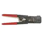


 工商网监
湘ICP备2023018690号
工商网监
湘ICP备2023018690号
