Industrial Automation
mPm DIN valve connectors
®
Conform to industry standard EN 175301-803
(formerly DIN 43650)
�Find the Latest Innovations
and Information at molex.com
For the most in-depth and up-to-date information on all our products,
visit molex.com. It’s designed to help you get more done in less time
with advanced search capabilities, 3D models, product specifications,
easy sample ordering and more.
molex.com provides a first stop for
comprehensive overviews of our
industrial products. Some of the tools
you'll find are:
Capabilities Videos
Short online videos highlight key
industry products, as well as our
unique cross-functional design and
manufacturing capabilities.
Featured Products
To find out about new products that
can take your design to the next level,
look no further than this convenient
product spotlight.
Other Time-Saving Site Features
Monthly E-nouncements
Electronic newsletter keeps you
up‑to‑date on our latest innovations
Favorite Products Feature
Let you select and save up to 200
products as you browse
New Videos, Webinars,
Articles and More
Available right from our home page
Detailed Application Pages
Instant Access to Product Specs
�TABLE OF CONTENTS
mPm® Field Attachable DIN Valve Connectors..................................................................................4.
Form A, Ext. Thread.....................................................................................................................................................6
Form Industrial, Ext. Thread........................................................................................................................................7.
Form B, Ext. Thread.....................................................................................................................................................8
Form C, Ext. Thread.....................................................................................................................................................9.
Form Micro, Ext. Thread............................................................................................................................................10
Form A, Intern. Thread..............................................................................................................................................11
Form Industrial, Intern. Thread..................................................................................................................................13.
Form B, Intern. Thread..............................................................................................................................................14.
Form C, Intern. Thread..............................................................................................................................................15
Micro Form, Intern. Thread........................................................................................................................................16
Form A, Intern. Thread..............................................................................................................................................17
Form Industrial, Intern. Thread..................................................................................................................................18
Form A, Intern. Thread..............................................................................................................................................19
mPm® Molded Cable DIN Valve Connectors.................................................................................... 20.
Form A, Overmolded.................................................................................................................................................22
Form Industrial, Overmolded.....................................................................................................................................23.
Form B, Overmolded.................................................................................................................................................24
Form C, Overmolded.................................................................................................................................................25.
Form Micro, Overmolded...........................................................................................................................................26
DIN Valve to Brad® M12, Overmolded.......................................................................................................................27.
DUAL DIN Valve, Overmolded...................................................................................................................................28.
DIN Valve to Brad® ILS, Overmolded.........................................................................................................................30.
DIN Valve to Brad® M12 Overmolded Adaptor..........................................................................................................31.
Cable Options............................................................................................................................................................32.
Circuit Options...........................................................................................................................................................33
mPm® DIN Bases for DIN Valve Connectors.................................................................................... 34.
mPm® DIN Adaptors for DIN Valve Connectors............................................................................... 40
mPm® DIN Spare Parts for DIN Valve Connectors........................................................................... 49
Supply Voltage and LED Color...................................................................................................................................33.
Ground PIN Position...................................................................................................................................................51.
�MOLEX DIN VALVE CONNECTOR
SOLUTIONS
EMPHASIZE PERFORMANCE AND
RELIABILITY
The Molex range of field
attachable DIN valve connectors
provide unsurpassed sealing
properties and increase performance, simplify manufacturing
processes, reduce inventory
and lower applied costs for
hydraulic, pneumatic and
electromagnetic devices as
well as sensors.
�Source: Siemens AG
mPm®
Field Attachable
DIN Valve Connectors
Conform to EN 175301-803 (ex DIN 43650)
The mPm® range of connectors is used extensively
to provide electrical connection in a wide range of
applications. The most common application for mPm
DIN connectors is in conjunction with pneumatic,
hydraulic or electromagnetic devices, including
solenoid valves. Other applications include, for
example, pressure transducers, proximity switches,
level sensors, limit switches and low energy motors.
Molex manufactures an extensive and comprehensive
range of connectors with standard options including
for example LED illuminated devices as well as VDR,
diodes or transil diodes (with or without illuminated
device) to offer protection against overvoltage peaks.
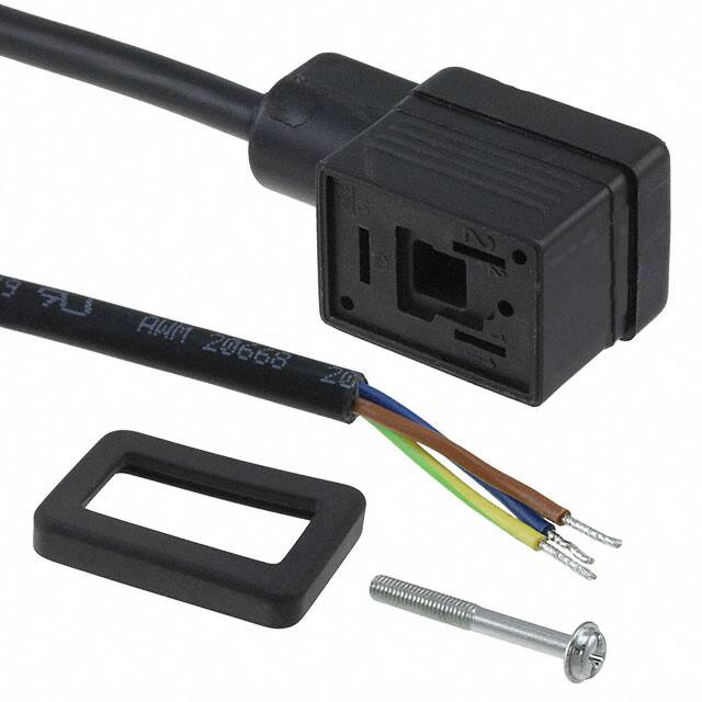
Brad® DIN mPm connectors offer protection from dust
and water (IP65 or IP67 on specific request) when
correctly installed with screw and gasket which are
supplied together with the connector.
�IP67 rated DIN valve connectors with improved strain relief.
Cable retention force increased by up to 20% over internal
nut styles. Enlarged cable range that covers the PG9 and
PG11 internal thread connector cable range. Conforms to
EN 175301-803.
Specifications
ELECTRICAL
Max. Current: 16.0A
Contact Resistance:
≤ 15 miliohms max.
Insulation Resistance:
100 Megohms min.
Max. Conductor: 1.50mm² / 16AWG
MECHANICAL
Insertion and Withdrawal Force:
2+GND ≤ 60N
Certification
UL recognized cURus marked, file
E218123 (product available upon
request or specific part number)
Non Electronic
PHYSICAL
Durability: min. 50 cycles
Contact Area: Silver
Solder Tail Area: Silver
Operating Temperature with:
Nitrile Rubber (NBR) Gasket:
-40° to +90°C
Silicone Gasket: -40° to +125°C
Cable Diameter Range: 4.00-9.00mm
Live Contact Distance:
18.00mm
mPm®
Field Attachable
DIN Valve
Connectors
121201 Form A, Ext. Thread,
Non-Electronic
121207 Form A, Ext. Thread,
Electronic
EnvironmentAL
IP67 Sealing Protection
C28 2 00 N 0 R
**
SERIES
C28=External Thread Form A
IP67
POLES
2=2Poles+Ground 3=3Poles+Ground
THREAD
00=External Thread
COVER COLOR
N=Black Cover G=Gray Cover
W=V0 Black Cover (only with UL listed connectors)
GROUND POSITION
0=Unmounted 2=H12 3=H3 6=H6 9=H9
SCREW & GASKET
R=Integrated NBR Gasket & IP67 Screw, S=Integrated Silicone Gasket & IP67 Screw
PACKAGING STYLE
no digit=Single Bag Unmounted, SN=Bulk Pack Mounted, CN=Bulk Pack Unmounted
Electronic
S28 2 00 T C4 2 0 R * *
SERIES
S28=External Thread Form A
POLES
2=2Poles+Ground
THREAD
00=External Thread
COVER COLOR
N=Black Cover G=Gray Cover T=Transparent
Circuit
see page 33
VOLTAGE & LED COLOR
see page 33
Note: UL listed part number identified by adding suffix
SA at the end of the nomenclature in conjunction with
UL material (W for black and T for transparent) e.g.
C28200W2RSNSA
GROUND POSITION
0=Unmounted 2=H12 3=H3 6=H6 9=H9
SCREW & GASKET
R=Integrated NBR Gasket & IP67 Screw, S=Integrated Silicone Gasket & IP67 Screw
Build your connector using the intelligent
part number system and contact your local
sales representative to identify the proper
EDP number to use in your purchase orders
PACKAGING STYLE
no digit=Single Bag Unmounted, SN=Bulk Pack Mounted, CN=Bulk Pack Unmounted
Packaging Type
Single Bag
6
Unmounted
Bulk Pack
Mounted
Single Bag
Unmounted
Bulk Pack
Mounted
Single Bag
Unmounted
Bulk Pack
mounted
Single Bag
Unmounted
Bulk Pack
mounted
Poles
2+Ground
3+Ground
2+Ground
Circuit
Voltage
LED Color
Engineering No.
Standard Order No.
NO
250V AC/300V DC
NO
C28200N0R
121201-0001
NO
250V AC/300V DC
NO
C28200N2RSN
121201-0034
NO
250V AC/300V DC
NO
C28300N0R
121201-0002
NO
250V AC/300V DC
NO
C28300N2RSN
121201-0038
C4
24V AC/DC
yellow
S28200TC4H0R
121207-0005
C4
24V AC/DC
yellow
S28200TC4H2RSN
121207-0368
C4
230V AC/DC
yellow
S28200TC4M0R
121207-0106
C4
230V AC/DC
yellow
S28200TC4M2RSN
121207-0371
www.molex.com
�IP67 rated DIN valve connector with improved strain relief.
Cable retention force increased up to 20% over internal nut
style. Enlarged cable range that covers the PG9 and PG11
internal thread connectors cable range.
Specifications
ELECTRICAL
Max. Current 16.0A
Contact Resistance: ≤15milliohms max.
Insulation Resistance:
100Megohms min.
Max. Conductor: 1.50mm2 / 16AWG
MECHANICAL
Insertion and Withdrawal Force:
2+GND ≤ 60N
Certification
UL recognized, cURus marked, file
E218123 (product available upon
request or specific part number)
Non Electronic
PHYSICAL
Durability: min. 50 cycles
Contact Area: Silver
Solder Tail Area: Silver
Operating Temperature with:
Nitrile Rubber (NBR) Gasket:
-40° +90°C
Silicone Gasket: -40° +125°C
Cable Diameter Range: 4.00-9.00mm
Live Contact Distance: 11.00mm
mPm®
Field Attachable
DIN Valve
Connectors
121202 Form Industrial,
Ext. Thread, Non-Electronic
121208 Form Industrial,
Ext. Thread, Electronic
EnvironmentAL
IP67 Sealing Protection
C22 2 00 N 0 R
**
SERIES
C22=External Thread Form Industrial
IP67
POLES
2=2Poles+Ground
THREAD
00=External Thread
COVER COLOR
N=Black Cover G=Gray Cover
W=V0 Black Cover (only with UL listed connectors)
GROUND POSITION
0=Unmounted 2=H12 6=H6
SCREW & GASKET
R=Integrated NBR Gasket & IP67 Screw, S=Integrated Silicone Gasket & IP67 Screw
PACKAGING STYLE
no digit=Single Bag Unmounted, SN=Bulk Pack Mounted, CN=Bulk Pack Unmounted
Electronic
S22 2 00 T C4 2 0 R * *
SERIES
S22=External Thread Form Industrial
POLES
2=2Poles+Ground
THREAD
00=External Thread
COVER COLOR
N=Black Cover G=Gray Cover T=Transparent
Circuit
see page 33
VOLTAGE & LED COLOR
see page 33
Note: UL listed part number identified by adding suffix
SA at the end of the nomenclature in conjunction with
UL material (W for black and T for transparent) e.g.
C28200W2RSNSA
GROUND POSITION
0=Unmounted 2=H12 6=H6
SCREW & GASKET
R=Integrated NBR Gasket & IP67 Screw, S=Integrated Silicone Gasket & IP67 Screw
Build your connector using the intelligent
part number system and contact your local
sales representative to identify the proper
EDP number to use in your purchase orders
PACKAGING STYLE
no digit=Single Bag Unmounted, SN=Bulk Pack Mounted, CN=Bulk Pack Unmounted
Packaging Type
Single Bag
Circuit
Voltage
LED Color
Engineering No.
Standard Order No.
Unmounted
Poles
NO
250V AC/300V DC
NO
C22200N0R
1212020001
Bulk Pack
Mounted
NO
250V AC/300V DC
NO
C22200N2RSN
1212020012
Single Bag
Unmounted
C4
24V AC/DC
yellow
S22200TC4H0R
1212080080
Bulk Pack
Mounted
C4
24V AC/DC
yellow
S22200TC4H2RSN
1212080240
Single Bag
Unmounted
C4
230V AC/DC
yellow
S22200TC4M0R
1212080083
Bulk Pack
Mounted
C4
230V AC/DC
yellow
S22200TC4M2RSN
1212080243
www.molex.com
2+Ground
7
�IP67 rated DIN valve connector with improved strain relief.
Cable retention force increased up to 20% over internal nut
style. Enlarged cable range that covers the PG9 and PG11
internal thread connectors cable range. Conforms to EN
175301-803
Specifications
ELECTRICAL
Current: max. 16.0A
Contact Resistance: ≤15milliohms max.
Insulation Resistance:
100Megohms min.
Max. Conductor: 1.50mm2 / 16AWG
MECHANICAL
Insertion and Withdrawal Force:
2+GND ≤ 60N
Certification
UL recognized, cURus marked, file
E218123 (product available upon
request or specific part number)
Non Electronic
PHYSICAL
Durability: min. 50 cycles
Contact Area: Silver
Solder Tail Area: Silver
Operating Temperature with:
Nitrile Rubber (NBR) Gasket:
-40° +90°C
Silicone Gasket: -40° +125°C
Cable Diameter Range: 4.00-9.00mm
Live Contact Distance: 10.00mm
mPm®
Field Attachable
DIN Valve
Connectors
121203 Form B, Ext. Thread,
Non-Electronic
121209 Form B, Ext. Thread,
Electronic
EnvironmentAL
IP67 Sealing Protection
C 92 2 0 0 N 0 T
**
SERIES
C92=External Thread Form B
IP67
POLES
2=2Poles+Ground
THREAD
00=External Thread
COVER COLOR
N=Black Cover G=Gray Cover
W=V0 Black Cover (only with UL listed connectors)
GROUND POSITION
0=Unmounted 2=H12 6=H6
SCREW & GASKET
T=Profile NBR Gasket & IP67 Screw, U=Profile Silicone Gasket & IP67 Screw
PACKAGING STYLE
no digit=Single Bag Unmounted, SN=Bulk Pack Mounted, CN=Bulk Pack Unmounted
Electronic
S 92 2 0 0 T C 4 2 0 T * *
SERIES
S92=External Thread Form B
POLES
2=2Poles+Ground
THREAD
00=External Thread
COVER COLOR
N=Black Cover G=Gray Cover T=Transparent
Circuit
see page 33
VOLTAGE & LED COLOR
see page 33
GROUND POSITION
0=Unmounted 2=H12 6=H6
Note: UL listed part number identified by adding suffix
SA at the end of the nomenclature in conjunction with
UL material (W for black and T for transparent) e.g.
C28200W2RSNSA
SCREW & GASKET
T=Profile NBR Gasket & IP67 Screw, U=Profile Silicone Gasket & IP67 Screw
PACKAGING STYLE
no digit=Single Bag Unmounted, SN=Bulk Pack Mounted, CN=Bulk Pack Unmounted
Build your connector using the intelligent
part number system and contact your local
sales representative to identify the proper
EDP number to use in your purchase orders
Packaging Type
Single Bag
8
Circuit
Voltage
LED Color
Engineering No.
Standard Order No.
Unmounted
Poles
NO
250V AC/300V DC
NO
C92200N0T
121203-0001
Bulk Pack
Mounted
NO
250V AC/300V DC
NO
C92200N2TSN
121203-0009
Single Bag
Unmounted
C4
24V AC/DC
yellow
S92200TC4H0T
121209-0047
Bulk Pack
Mounted
C4
24V AC/DC
yellow
S92200TC4H2TSN
121209-0207
Single Bag
Unmounted
C4
230V AC/DC
yellow
S92200TC4M0T
121209-0050
Bulk Pack
Mounted
C4
230V AC/DC
yellow
S92200TC4M2TSN
121209-0210
2+Ground
www.molex.com
�IP67 rated DIN valve connector with improved strain relief.
Cable retention force increased up to 20% over internal nut
style. Enlarged cable range that covers the internal thread
connectors cable range. Conforms to EN 175301-803
Specifications
ELECTRICAL
Current: max. 10.0A
Contact Resistance: ≤15milliohms max.
Insulation Resistance:
100Megohms min.
Max. Conductor: 0.75mm2 / 18AWG
MECHANICAL
Insertion and Withdrawal Force:
2+GND ≤ 60N
Certification
UL recognized, cURus marked, file
E218123 (product available upon
request or specific part number)
Non Electronic
PHYSICAL
Durability: min. 50 cycles
Contact Area: Silver
Solder Tail Area: Silver
Operating Temperature with:
Nitrile Rubber (NBR) Gasket:
-40° +90°C
Silicone Gasket: -40° +125°C
Cable Diameter Range: 3.00-5.50mm
Live Contact Distance: 8.00mm
mPm®
Field Attachable
DIN Valve
Connectors
121204 Form C, Ext. Thread,
Non-Electronic
121210 Form C, Ext. Thread,
Electronic
EnvironmentAL
IP67 Sealing Protection
C 25 2 0 0 N 0 T
**
IP67
SERIES
C25=External Thread Form C
POLES
2=2Poles+Ground 3=3Poles+Ground
THREAD
00=External Thread
COVER COLOR
N=Black Cover G=Gray Cover
W=V0 Black Cover (only with UL listed connectors)
GROUND POSITION
0=Unmounted 2=H12 3=H3 6=H6 9=H9
SCREW & GASKET
T=Profile NBR Gasket & IP67 Screw, U=Profile Silicone Gasket & IP67 Screw
PACKAGING STYLE
no digit=Single Bag Unmounted, SN=Bulk Pack Mounted, CN=Bulk Pack Unmounted
Electronic
S 25 2 0 0 T C 4 2 0 T * *
SERIES
S25=External Thread Form C
POLES
2=2Poles+Ground
THREAD
00=External Thread
COVER COLOR
N=Black Cover G=Gray Cover T=Transparent
Circuit
see page 33
VOLTAGE & LED COLOR
see page 33
GROUND POSITION
0=Unmounted 2=H12 3=H3 6=H6 9=H9
Note: UL listed part number identified by adding suffix
SA at the end of the nomenclature in conjunction with
UL material (W for black and T for transparent) e.g.
C28200W2RSNSA
SCREW & GASKET
T=Profile NBR Gasket & IP67 Screw, U=Profile Silicone Gasket & IP67 Screw
PACKAGING STYLE
no digit=Single Bag Unmounted, SN=Bulk Pack Mounted, CN=Bulk Pack Unmounted
Build your connector using the intelligent
part number system and contact your local
sales representative to identify the proper
EDP number to use in your purchase orders
Packaging Type
Single Bag
Circuit
Voltage
LED Color
Engineering No.
Standard Order No.
Unmounted
Poles
NO
250V AC/300V DC
NO
C25200N0T
121204-0001
Bulk Pack
Mounted
NO
250V AC/300V DC
NO
C25200N2TSN
121204-0010
Single Bag
Unmounted
C4
24V AC/DC
yellow
S25200TC4H0T
121210-0042
Bulk Pack
Mounted
C4
24V AC/DC
yellow
S25200TC4H2TSN
121210-0342
Single Bag
Unmounted
C4
230V AC/DC
yellow
S25200TC4M0T
121210-0045
Bulk Pack
Mounted
C4
230V AC/DC
yellow
S25200TC4M2TSN
121210-0345
www.molex.com
2+Ground
9
�IP67 rated DIN valve connector with improved strain relief.
Cable retention force increased up to 20% over internal
nut style. Enlarged cable range that covers internal thread
connectors cable range.
Specifications
ELECTRICAL
Max. Current 10.0A
Contact Resistance: ≤15milliohms max.
Insulation Resistance:
100Megohms min.
Max Conductor: 0.75mm² / 18AWG
MECHANICAL
Insertion and Withdrawal Force:
2+GND ≤ 60N
Certification
UL recognized, cURus marked, file
E218123 (product available upon
request or specific part number)
Non Electronic
PHYSICAL
Durability: min. 50 cycles
Contact Area: Silver
Solder Tail Area: Silver
Operating Temperature with:
Nitrile Rubber (NBR) Gasket:
-40° +90°C
Silicone Gasket -40° to +125°C
Cable Diameter Range: 3.00-5.50mm
Live Contact Distance: 9.40mm
mPm®
Field Attachable
DIN Valve
Connectors
121205 Form Micro, Ext. Thread
Non-Electronic
121211 Form Micro, Ext. Thread
Electronic
EnvironmentAL
IP67 Sealing Protection
C29 2 00 N 0 T * *
SERIES
C29=External Thread Form Micro
IP67
POLES
2=2Poles+Ground 3=3Poles+Ground
THREAD
00=External Thread
COVER COLOR
N=Black Cover G=Gray Cover
W=V0 Black Cover (only with UL listed connectors)
GROUND POSITION
0=Unmounted 2=H12 3=H3 6=H6 9=H9
SCREW & GASKET
T=Profile NBR Gasket & IP67 Screw, U=Profile Silicone Gasket & IP67 Screw
PACKAGING STYLE
no digit=Single Bag Unmounted, SN=Bulk Pack Mounted, CN=Bulk Pack Unmounted
Electronic
S 29 2 0 0 T C 4 2 0 T * *
SERIES
S29=External Thread Form Micro
POLES
2=2Poles+Ground
THREAD
00=External Thread
COVER COLOR
N=Black Cover G=Gray Cover T=Transparent
Circuit
see page 33
VOLTAGE & LED COLOR
see page 33
GROUND POSITION
0=Unmounted 2=H12 3=H3 6=H6 9=H9
Note: UL listed part number identified by adding suffix
SA at the end of the nomenclature in conjunction with
UL material (W for black and T for transparent) e.g.
C28200W2RSNSA
SCREW & GASKET
T=Profile NBR Gasket & IP67 Screw, U=Profile Silicone Gasket & IP67 Screw
PACKAGING STYLE
no digit=Single Bag Unmounted, SN=Bulk Pack Mounted, CN=Bulk Pack Unmounted
Packaging Type
Single Bag
10
Poles
Build your connector using the intelligent
part number system and contact your local
sales representative to identify the proper
EDP number to use in your purchase orders
Circuit
Voltage
LED Color
Engineering No.
Standard Order No.
Unmounted
NO
250V AC/300V DC
NO
C29200N0T
121205-0001
Bulk Pack
Mounted
NO
250V AC/300V DC
NO
C29200N2TSN
121205-0012
Single Bag
Unmounted
C4
24V AC/DC
yellow
S29200TC4H0T
121211-0042
Bulk Pack
Mounted
C4
24V AC/DC
yellow
S29200TC4H2TSN
121211-0342
Single Bag
Unmounted
C4
230V AC/DC
yellow
S29200TC4M0T
121211-0045
Bulk Pack
Mounted
C4
230V AC/DC
yellow
S29200TC4M2TSN
121211-0345
2+Ground
www.molex.com
�Standard internal thread DIN valve connector, IP65 rated.
Available with different thread style, gaskets and circuitry.
Conforms to EN 175301-803
Specifications
ELECTRICAL
Max. Current: 16.0A
Contact Resistance: ≤15milliohms max.
Insulation Resistance:
100Megohms min.
Max. Conductor: 1.50mm² / 16AWG
MECHANICAL
Insertion and Withdrawal Force:
2+GND ≤ 60N
Certification
UL recognized, cURus marked, file
E218123 (product available upon
request or specific part number)
Non Electronic
PHYSICAL
Durability: min. 50 cycles
Contact Area: Silver
Solder Tail Area: Silver
Operating Temperature with:
Nitrile Rubber (NBR) Gasket:
-40° +90°C
Silicone -40° +125°C
Cable Diameter Range:
PG9-M16
6.00-8.00mm
PG11-G1/2“-M20 8.00-10.00mm
Live Contact Distance: 18.00mm
mPm®
Field Attachable
DIN Valve
Connectors
121023 Form A, Intern. Thread,
Non-Electronic
121064 Form A, Intern. Thread,
Electronic
EnvironmentAL
IP65 sealing protection
(IP67 available on request)
C 18 2 0 9 N 2 1
SERIES
C18=Internal Thread Form A
POLES
2=2Poles+Ground 3=3Poles+Ground
THREAD
09=PG9 11=PG11 M6=M16x1,5 M0=M20x1,5
12=1/2" GAS 13=1/2 NPTF
COVER COLOR
N=Black Cover G=Gray Cover
W=V0 Black Cover (only with UL listed connectors)
GROUND POSITION
2=H12 3=H3 6=H6 9=H9
SCREW & GASKET
1=Profile NBR Gasket & Screw, 2=Flat NBR Gasket & Screw
3=White Silicone Profile Gasket & Screw, 4=White Silicone Flat Gasket & Screw
Electronic
S 18 2 0 9 T C 4 2 1
SERIES
S18=Internal Thread Form A
POLES
2=2Poles+Ground
THREAD
09=PG9 11=PG11 M6=M16x1,5 M0=M20x1,5
12=1/2" GAS 13=1/2 NPTF
COVER COLOR
N=Black Cover G=Gray Cover T=Transparent
Note: UL listed part number identified by adding suffix
SA at the end of the nomenclature in conjunction with
UL material (W for black and T for transparent) e.g.
C28200W2RSNSA
Circuit
see page 33
VOLTAGE & LED COLOR
see page 33
SCREW & GASKET
1=Profile NBR Gasket & Screw, 2=Flat NBR Gasket & Screw
3=White Silicone Profile Gasket & Screw, 4=White Silicone Flat Gasket & Screw
Packaging Type
Poles
2+Ground
3+Ground
Bulk Pack
Mounted
2+Ground
www.molex.com
Build your connector using the intelligent
part number system and contact your local
sales representative to identify the proper
EDP number to use in your purchase orders
Circuit
Voltage
LED Color
Engineering No.
Standard Order No.
NO
250V AC/300V DC
NO
C18209N21
121023-0238
NO
250V AC/300V DC
NO
C18211N21
121023-0278
NO
250V AC/300V DC
NO
C18309N21
121023-0341
NO
250V AC/300V DC
NO
C18311N21
121023-0377
C4
24V AC/DC
yellow
S18209TC4H1
121064-0600
C4
230V AC/DC
yellow
S18209TC4M1
121064-0603
C4
24V AC/DC
yellow
S18211TC4H1
121064-0685
C4
230V AC/DC
yellow
S18211TC4M1
121064-0687
11
�Standard internal thread DIN valve connector, IP65 rated.
Available with different thread style and gaskets.
Conforms to EN 175301-803
mPm®
Field Attachable
DIN Valve
Connectors
121023 Form A, Intern. Thread,
High Space Non-Electronic
Specifications
ELECTRICAL
Max. Current: 16.0A
Contact Resistance: ≤15milliohms max.
Insulation Resistance:
100Megohms min.
Max. Conductor: 1.50mm2 / 16AWG
MECHANICAL
Insertion and Withdrawal Force:
2+GND ≤ 60N
Certification
UL recognized, cURus marked, file
E218123 (product available upon
request or specific part number)
Non Electronic
PHYSICAL
Durability: min. 50 cycles
Contact Area: Silver
Solder Tail Area: Silver
Operating Temperature with:
Nitrile Rubber (NBR) Gasket:
-40° +90°C
Silicone Gasket: -40° +125°C
Cable Diameter Range:
PG9-M16
6.00-8.00mm
PG11-G1/2“-M20 8.00-10.00mm
Live Contact Distance: 18.00mm
EnvironmentAL
IP65 sealing protection
(IP67 available on request)
C 81 2 0 9 N 2 1
SERIES
C81=Internal Thread Form A High Space
POLES
2=2Poles+Ground 3=3Poles+Ground
THREAD
09=PG9 11=PG11 M6=M16x1,5 M0=M20x1,5
12=1/2" GAS
COVER COLOR
N=Black Cover G=Gray Cover
W=V0 Black Cover (only with UL listed connectors)
GROUND POSITION
2=H12 3=H3 6=H6 9=H9
SCREW & GASKET
1=Profile NBR Gasket & Screw, 2=Flat NBR Gasket & Screw
3=White Silicone Profile Gasket & Screw, 4=White Silicone Flat Gasket & Screw
Note: UL listed part number identified by adding suffix
SA at the end of the nomenclature in conjunction with
UL material (W for black and T for transparent) e.g.
C28200W2RSNSA
Build your connector using the intelligent
part number system and contact your local
sales representative to identify the proper
EDP number to use in your purchase orders
Packaging Type
Poles
2+Ground
Bulk Pack
Mounted
3+Ground
12
Circuit
Voltage
LED Color
Engineering No.
Standard Order No.
NO
250V AC/300V DC
NO
C81209N21
121023-0612
NO
250V AC/300V DC
NO
C81211N21
121023-0620
NO
250V AC/300V DC
NO
C81309N21
121023-0629
NO
250V AC/300V DC
NO
C81311N21
121023-0633
www.molex.com
�Standard internal thread DIN valve connector, IP65 rated.
Available with different thread style, gaskets and circuitry.
121023 Form Industrial,
Intern. Thread, Non-Electronic
121064 Form Industrial,
Intern. Thread, Electronic
Specifications
ELECTRICAL
Max. Current: 16.0A
Contact Resistance: ≤15milliohms max.
Insulation Resistance:
100Megohms min.
Max. Conductor: 1.50mm2 / 16AWG
MECHANICAL
Insertion and Withdrawal Force:
2+GND ≤ 60N
Certification
UL recognized, cURus marked, file
E218123 (product available upon
request or specific part number)
Non Electronic
mPm®
Field Attachable
DIN Valve
Connectors
PHYSICAL
Durability: min. 50 cycles
Contact Area: Silver
Solder Tail Area: Silver
Operating Temperature with:
Nitrile Rubber (NBR) Gasket:
-40° +90°C
Silicone Gasket: -40° +125°C
Cable Diameter Range:
PG7-M12
4.00-6.00mm
PG9-M16
6.00-8.00mm
M20 8.00-10.00mm
Live Contact Distance: 11.00mm
EnvironmentAL
IP65 sealing protection
(IP67 available on request)
C 12 2 0 7 N 2 1
SERIES
C12=Internal Thread Form Industrial
POLES
2=2Poles+Ground
THREAD
07=PG7 09=PG9 M2=M12x1,5 M6=M16x1,5
M0=M20x1,5 13=1/2" NPTF
COVER COLOR
N=Black Cover G=Gray Cover
W=V0 Black Cover (only with UL listed connectors)
GROUND POSITION
2=H12 6=H6
SCREW & GASKET
1=Profile NBR Gasket & Screw, 2=Flat NBR Gasket & Screw
3=White Silicone Profile Gasket & Screw, 4=White Silicone Flat Gasket & Screw
Electronic
S 02 2 0 7 T C 4 2 1
SERIES
S02=Internal Thread Form Industrial
POLES
2=2Poles+Ground
THREAD
07=PG7 09=PG9 M2=M12x1,5 M6=M16x1,5
M0=M20x1,5 13=1/2" NPTF
COVER COLOR
N=Black Cover G=Gray Cover T=Transparent
Circuit
see page 33
VOLTAGE & LED COLOR
see page 33
SCREW & GASKET
1=Profile NBR Gasket & Screw, 2=Flat NBR Gasket & Screw
3=White Silicone Profile Gasket & Screw, 4=White Silicone Flat Gasket & Screw
Note: UL listed part number identified by adding suffix
SA at the end of the nomenclature in conjunction with
UL material (W for black and T for transparent) e.g.
C28200W2RSNSA
Build your connector using the intelligent
part number system and contact your local
sales representative to identify the proper
EDP number to use in your purchase orders
Packaging Type
Bulk Pack
www.molex.com
Mounted
Poles
2+Ground
Circuit
Voltage
LED Color
Engineering No.
Standard Order No.
NO
250V AC/300V DC
NO
C12207N21
121023-0105
NO
250V AC/300V DC
NO
C12209N21
121023-0122
C4
24V AC/DC
yellow
S02209TC4H1
121064-0120
C4
230V AC/DC
yellow
S02209TC4M1
121064-0124
13
�Standard internal thread DIN valve connector, IP65 rated.
Available with different thread style, gaskets and circuitry.
Conforms to EN 175301-803.
Specifications
ELECTRICAL
Max. Current: 16.0A
Contact Resistance: ≤15milliohms max.
Insulation Resistance:
100Megohms min.
Max. Conductor: 1.50mm2 / 16AWG
MECHANICAL
Insertion and Withdrawal Force:
2+GND ≤ 60N
Certification
UL recognized, cURus marked, file
E218123 (product available upon
request or specific part number)
Non Electronic
PHYSICAL
Durability: min. 50 cycles
Contact Area: Silver
Solder Tail Area: Silver
Operating Temperature with:
Nitrile Rubber (NBR) Gasket:
-40° +90°C
Silicone Gasket: -40° +125°C
Cable Diameter Range:
PG7-M12
4.00-6.00mm
PG9-M16
6.00-8.00mm
Live Contact Distance: 10.00mm
mPm®
Field Attachable
DIN Valve
Connectors
121023 Form B, Intern. Thread,
Non-Electronic
121064 Form B, Intern. Thread,
Electronic
EnvironmentAL
IP65 sealing protection
(IP67 available on request)
C 62 2 0 7 N 2 1
SERIES
C62=Internal Thread Form B
POLES
2=2Poles+Ground
THREAD
07=PG7 09=PG9 M2=M12x1,5 M6=M16x1,5
COVER COLOR
N=Black Cover G=Gray Cover
W=V0 Black Cover (only with UL listed connectors)
GROUND POSITION
2=H12 6=H6
SCREW & GASKET
1=Profile NBR Gasket & Screw, 2=Flat NBR Gasket & Screw
3=White Silicone Profile Gasket & Screw, 4=White Silicone Flat Gasket & Screw
Electronic
S 62 2 0 7 T C 4 2 1
SERIES
S62=Internal Thread Form B
POLES
2=2Poles+Ground
THREAD
07=PG7 09=PG9 M2=M12x1,5 M6=M16x1,5
COVER COLOR
N=Black Cover G=Gray Cover T=Transparent
Circuit
see page 33
VOLTAGE & LED COLOR
see page 33
SCREW & GASKET
1=Profile NBR Gasket & Screw, 2=Flat NBR Gasket & Screw
3=White Silicone Profile Gasket & Screw, 4=White Silicone Flat Gasket & Screw
Note: UL listed part number identified by adding suffix
SA at the end of the nomenclature in conjunction with
UL material (W for black and T for transparent) e.g.
C28200W2RSNSA
Build your connector using the intelligent
part number system and contact your local
sales representative to identify the proper
EDP number to use in your purchase orders
Packaging Type
Bulk Pack
14
Mounted
Poles
2+Ground
Circuit
Voltage
LED Color
Engineering No.
Standard Order No.
NO
250V AC/300V DC
NO
C62207N21
121023-0569
NO
250V AC/300V DC
NO
C62209N21
121023-0571
C4
24V AC/DC
yellow
S62209TC4H1
121064-1239
C4
230V AC/DC
yellow
S62209TC4M1
121064-1241
www.molex.com
�Standard internal thread DIN valve connector, IP65 rated.
Available with different thread style, gaskets and circuitry.
Conforms to EN 175301-803.
121023 Form C, Intern. Thread,
Non-Electronic
121064 Form C, Intern. Thread,
Electronic
Specifications
ELECTRICAL
Max. Current: 10.0A
Contact Resistance: ≤15milliohms max.
Insulation Resistance:
100Megohms min.
Max. Conductor: 0.75mm² / 18AWG
MECHANICAL
Insertion and Withdrawal Force:
2+GND ≤ 60N
Certification
UL recognized, cURus marked, file
E218123 (product available upon
request or specific part number)
Non Electronic
mPm®
Field Attachable
DIN Valve
Connectors
PHYSICAL
Durability: min. 50 cycles
Contact Area: Silver
Solder Tail Area: Silver
Operating Temperature with:
Nitrile Rubber (NBR) Gasket:
-40° +90°C
Silicone Gasket: -40° +125°C
Cable Diameter Range:
PG7-M12
4.00-6.00mm
Live Contact Distance: 8.00mm
EnvironmentAL
IP65 sealing protection
(IP67 available on request)
C 05 2 0 7 N 2 1
SERIES
C05=Internal Thread Form C
POLES
2=2Poles+Ground 3=3Poles+Ground
THREAD
07=PG7 M2=M12x1,5
COVER COLOR
N=Black Cover G=Gray Cover
W=V0 Black Cover (only with UL listed connectors)
GROUND POSITION
2=H12 3=H3 6=H6 9=H9
SCREW & GASKET
1=Profile NBR Gasket & Screw, 2=Flat NBR Gasket & Screw
3=White Silicone Profile Gasket & Screw, 4=White Silicone Flat Gasket & Screw
Electronic
S 05 2 0 7 T C 4 2 1
SERIES
S05=Internal Thread Form C
POLES
2=2Poles+Ground
THREAD
07=PG7 M2=M12x1,5
COVER COLOR
N=Black Cover G=Gray Cover T=Transparent
Circuit
see page 33
VOLTAGE & LED COLOR
see page 33
SCREW & GASKET
1=Profile NBR Gasket & Screw, 2=Flat NBR Gasket & Screw
3=White Silicone Profile Gasket & Screw, 4=White Silicone Flat Gasket & Screw
Note: UL listed part number identified by adding suffix
SA at the end of the nomenclature in conjunction with
UL material (W for black and T for transparent) e.g.
C28200W2RSNSA
Build your connector using the intelligent
part number system and contact your local
sales representative to identify the proper
EDP number to use in your purchase orders
Packaging Type
Bulk Pack
Mounted
Poles
Circuit
Voltage
LED Color
Engineering No.
Standard Order No.
2+Ground
NO
250V AC/300V DC
NO
C05207N21
121023-0083
3+Ground
NO
250V AC/300V DC
NO
C05307N21
121023-0684
C4
24V AC/DC
yellow
S05207TC4H1
121064-1253
C4
230V AC/DC
yellow
S05207TC4M1
121064-1446
2+Ground
www.molex.com
15
�Standard internal thread DIN valve connector, IP65 rated.
Available with different thread style, gaskets and circuitry.
Specifications
ELECTRICAL
Max. Current: 10.0A
Contact Resistance: ≤15milliohms max.
Insulation Resistance:
100Megohms min.
Max. Conductor: 0.75mm2 / 18AWG
MECHANICAL
Insertion and Withdrawal Force:
2+GND ≤ 60N
Certification
UL recognized, cURus marked, file
E218123 (product available upon
request or specific part number)
Non Electronic
PHYSICAL
Durability: min. 50 cycles
Contact Area: Silver
Solder Tail Area: Silver
Operating Temperature with:
Nitrile Rubber (NBR) Gasket:
-40° +90°C
Silicone Gasket: -40° +125°C
Cable Diameter Range:
PG7-M12
4.00-6.00mm
Live Contact Distance: 9.40mm
mPm®
Field Attachable
DIN Valve
Connectors
121023 Micro Form,
Intern. Thread, Non-Electronic
121064 Micro Form,
Intern. Thread, Electronic
EnvironmentAL
IP65 sealing protection
(IP67 available on request)
C 19 2 0 7 N 2 1
SERIES
C19=Internal Thread Form Micro
POLES
2=2Poles+Ground 3=3Poles+Ground
THREAD
07=PG7 M2=M12x1,5
COVER COLOR
N=Black Cover G=Gray Cover
W=V0 Black Cover (only with UL listed connectors)
GROUND POSITION
2=H12 3=H3 6=H6 9=H9
SCREW & GASKET
1=Profile NBR Gasket & Screw, 2=Flat NBR Gasket & Screw
3=White Silicone Profile Gasket & Screw, 4=White Silicone Flat Gasket & Screw
Electronic
S 19 2 0 7 T C 4 2 1
SERIES
S19=Internal Thread Form Micro
POLES
2=2Poles+Ground
THREAD
07=PG7 M2=M12x1,5
COVER COLOR
N=Black Cover G=Gray Cover T=Transparent
Circuit
see page 33
VOLTAGE & LED COLOR
see page 33
SCREW & GASKET
1=Profile NBR Gasket & Screw, 2=Flat NBR Gasket & Screw
3=White Silicone Profile Gasket & Screw, 4=White Silicone Flat Gasket & Screw
Note: UL listed part number identified by adding suffix
SA at the end of the nomenclature in conjunction with
UL material (W for black and T for transparent) e.g.
C28200W2RSNSA
Build your connector using the intelligent
part number system and contact your local
sales representative to identify the proper
EDP number to use in your purchase orders
Packaging Type
Bulk Pack
Mounted
Poles
Circuit
Voltage
LED Color
Engineering No.
Standard Order No.
2+Ground
NO
250V AC/300V DC
NO
C19207N21
121023-0433
3+Ground
NO
250V AC/300V DC
NO
C19307N21
121023-0464
C4
24V AC/DC
yellow
S19207TC4H1
121064-0871
C4
230V AC/DC
yellow
S19207TC4M1
121064-1342
2+Ground
16
www.molex.com
�Standard internal thread DIN valve connector, IP65 rated.
Available with different thread style, gaskets and circuitry.
Conforms to EN 175301-803
mPm®
Field Attachable
DIN Valve
Connectors
121064 Form A, Intern. Thread,
Electronic
Specifications
ELECTRICAL
Max. Current: 16.0A
Contact Resistance: ≤15milliohms max.
Insulation Resistance:
100Megohms min.
Max. Conductor: 1.50mm² / 16AWG
MECHANICAL
Insertion and Withdrawal Force:
2+GND ≤ 60N
Certification
UL recognized, cURus marked, file
E218123 (product available upon
request or specific part number)
Electronic
PHYSICAL
Durability: min. 50 cycles
Contact Area: Silver
Operating Temperature with:
Nitrile Rubber (NBR) Gasket:
-40° +90°C
Silicone Gasket: -40° +125°C
Cable Diameter Range:
PG9-M12
6.00-8.00mm
PG11 8.00-10.00mm
Live Contact Distance: 18.00mm
EnvironmentAL
IP65 sealing protection
(IP67 available on request)
S 53 2 11 T C 4 2 1
SERIES
S53=Internal Thread Form A
POLES
2=2Poles+Ground
THREAD
09=PG9 11=PG11 M6=M16x1,5
COVER COLOR
N=Black Cover G=Gray Cover T=Transparent
W=V0 Black Cover (only with UL listed Conn)
Circuit
see page 33
VOLTAGE & LED COLOR
see page 33
SCREW & GASKET
1=Profile NBR Gasket & Screw, 2=Flat NBR Gasket & Screw
3=White Silicone Profile Gasket & Screw, 4=White Silicone Flat Gasket & Screw
Note: UL listed part number identified by adding suffix
SA at the end of the nomenclature in conjunction with
UL material (W for black and T for transparent) e.g.
C28200W2RSNSA
Build your connector using the intelligent
part number system and contact your local
sales representative to identify the proper
EDP number to use in your purchase orders
Packaging Type
Bulk Pack
www.molex.com
Mounted
Poles
2+Ground
Circuit
Voltage
LED Color
Engineering No.
Standard Order No.
R0
24V AC
NO
S53209NR021
121064-0896
R0
230V AC
NO
S53209NR051
121064-0900
R2
24V AC
yellow
S53209TR2H1
121064-0953
R2
230V AC
yellow
S53209TR2M1
121064-0955
17
�Standard internal thread DIN valve connector, IP65 rated.
Available with different thread style, gaskets and circuitry.
mPm®
Field Attachable
DIN Valve
Connectors
121064 Form Industrial,
Intern. Thread, Electronic
Specifications
ELECTRICAL
Max. Current: 16.0A
Contact Resistance: ≤15milliohms max.
Insulation Resistance:
100Megohms min.
Max. Conductor: 1.50mm² / 16AWG
MECHANICAL
Insertion and Withdrawal Force:
2+GND ≤ 60N
Certification
UL recognized, cURus marked, file
E218123 (product available upon
request or specific part number)
Electronic
PHYSICAL
Durability: min. 50 cycles
Contact Area: Silver
Operating Temperature with:
Nitrile Rubber (NBR) Gasket:
-40° +90°C
Silicone Gasket: -40° +125°C
Cable Diameter Range:
PG7-M12 4.00-6.00mm
PG9-M16 6.00-8.00mm
Live Contact Distance: 11.00mm
EnvironmentAL
IP65 sealing protection
(IP67 available on request)
S 54 2 0 9 T C 4 2 1
SERIES
S54=Internal Thread Form Industrial
POLES
2=2Poles+Ground
THREAD
07=PG7 09=PG9 M2=M12x1,5 M6=M16x1,5
COVER COLOR
N=Black Cover G=Gray Cover T=Transparent
W=V0 Black Cover (only with UL listed Conn)
Circuit
see page 33
VOLTAGE & LED COLOR
see page 33
SCREW & GASKET
1=Profile NBR Gasket & Screw, 2=Flat NBR Gasket & Screw
3=White Silicone Profile Gasket & Screw, 4=White Silicone Flat Gasket & Screw
Note: UL listed part number identified by adding suffix
SA at the end of the nomenclature in conjunction with
UL material (W for black and T for transparent) e.g.
C28200W2RSNSA
Build your connector using the intelligent
part number system and contact your local
sales representative to identify the proper
EDP number to use in your purchase orders
Packaging Type
Bulk Pack
18
Mounted
Poles
2+Ground
Circuit
Voltage
LED Color
Engineering No.
Standard Order No.
R0
24V AC
NO
S54209NR021
121064-1036
R0
230V AC
NO
S54209NR051
121064-1038
R2
24V AC
yellow
S54209TR2H1
121064-1083
R2
230V AC
yellow
S54209TR2M1
121064-1810
www.molex.com
�Standard internal thread DIN valve connector, IP65 rated.
Available with different thread style, gaskets and circuitry.
Conforms to EN 175301-803
mPm®
Field Attachable
DIN Valve
Connectors
121064 Form A, Intern. Thread,
Electronic
Specifications
ELECTRICAL
Max. Current: 16.0A
Contact Resistance: ≤15milliohms max.
Insulation Resistance:
100Megohms min.
Max. Conductor: 1.50mm² / 16AWG
MECHANICAL
Insertion and Withdrawal Force:
2+GND ≤ 60N
Certification
UL recognized, cURus marked, file
E218123 (product available upon
request or specific part number)
Electronic
PHYSICAL
Durability: min. 50 cycles
Contact Area: Silver
Operating Temperature with:
Nitrile Rubber (NBR) Gasket:
-40° +90°C
Silicone Gasket: -40° +125°C
Cable Diameter Range:
PG9-M16 6.00-8.00mm
PG11-M20 8.00-10.00mm
Live Contact Distance: 18.00mm
EnvironmentAL
IP65 sealing protection
(IP67 available on request)
S 11 2 0 9 T C 4 2 1
SERIES
S11=Internal Thread Form A
POLES
2=2Poles+Ground 3=3Poles+Ground
THREAD
09=PG7 11=PG7 M6=M16x1,5
COVER COLOR
N=Black Cover G=Gray Cover T=Transparent
W=V0 Black Cover (only with UL listed Conn)
Circuit
see page 33
VOLTAGE & LED COLOR
see page 33
SCREW & GASKET
1=Profile NBR Gasket & Screw, 2=Flat NBR Gasket & Screw
3=White Silicone Profile Gasket & Screw, 4=White Silicone Flat Gasket & Screw
Note: UL listed part number identified by adding suffix
SA at the end of the nomenclature in conjunction with
UL material (W for black and T for transparent) e.g.
C28200W2RSNSA
Build your connector using the intelligent
part number system and contact your local
sales representative to identify the proper
EDP number to use in your purchase orders
Packaging Type
Bulk Pack
www.molex.com
Mounted
Poles
2+Ground
Circuit
Voltage
LED Color
Engineering No.
Standard Order No.
R0
24V AC
NO
S11209NR021
121064-0248
R0
230V AC
NO
S11209NR051
121064-0250
R2
24V AC
yellow
S11209NR2H1
121064-1811
R2
230V AC
yellow
S11209NR2M1
121064-1692
19
�PRE-WIRED SOLENOID CONNECTORS
CONFORM TO INDUSTRY STANDARD
EN 175301-803
When space and time are in
short supply, mPm® DIN valve
overmolded cordsets provide
the perfect solution which also
conform to Industry Standard
EN 175301-803 (formerly DIN
43650). This is the standard
for a series of electrical connectors, which are commonly
used with solenoid valves especially those used on
hydraulic and pneumatic
valves.
�mPm®
Molded Cable DIN Valve
Connectors
Conform to EN 175301-803 (ex DIN 43650)
Our connectors with integrated cable are suitable for
use with most types of solenoid valves. They offer
a fast and efficient method of connection resulting
in greatly reduced installation time and cost and
it is always preferred in rugged applications. They
can be supplied with or without LED indicators and
surge suppression circuit. A diagram is printed on
each electronic connector to allow an easy user
identification.
�mPm®
Molded Cable DIN
Valve Connectors
DIN Valve connectors with molded cable, IP65 rated.
IP67 version available on request.
Conforms to EN 175301-803.
121040 Form A, Overmolded
Non-Electronic
121050 Form A, Overmolded
Electronic
Specifications
ELECTRICAL
Current: max. 5.0A
Contact Resistance: ≤15milliohms max.
Insulation Resistance:
100Megohms min.
MECHANICAL
Insertion and Withdrawal Force:
2+GND ≤ 60N
Certification
UL recognized, cURus marked, file
E218123 (product available upon
request or specific part number)
Non Electronic
PHYSICAL
Durability: min. 50 cycles
Contact Area: Silver
Operating Temperature with:
Nitrile Rubber (NBR) Gasket:
-40° +90°C
Silicone Gasket: -40° +125°C
Live Contact Distance: 18.00mm
EnvironmentAL
IP65 sealing protection
(IP67 available on request)
E15 2 N2 N 300 1 1
SERIES
E15=Overmolded Cordset Form A
POLES
2=2Poles+Ground 3=3Poles+Ground
CABLE TYPE
see cable options on technical features page 32
HEAD COLOR
N=Black G=Gray A=UL Black (only with UL listed cable)
CABLE LENGTH
e.g. 050=50cm 300=3.0m 10K=10.0m
GROUND LOCATION
1=Double Ground H6/H12 2=H12 6=H6
SCREW & GASKET
1=Profile NBR Gasket & Screw, 2=Flat NBR Gasket & Screw
3=White Silicone Profile Gasket & Screw, 4=White Silicone Flat Gasket & Screw
P=NBR Integrated Gasket Assembled + IP67 Screw
Electronic
E45 2 N2 N 300 1 1 C4 2
SERIES
E45=Overmolded Cordset Form A
POLES
2=2Poles+Ground
CABLE TYPE
see cable options on technical features page 32
HEAD COLOR
N=Black G=Gray A=UL Black (only with UL listed cable)
CABLE LENGTH
e.g. 050=50cm 300=3.0m 10K=10.0m
GROUND LOCATION
1=Double Ground H6/H12
SCREW & GASKET
1=Profile NBR Gasket & Screw, 2=Flat NBR Gasket & Screw
3=White Silicone Profile Gasket & Screw, 4=White Silicone Flat Gasket & Screw
P=NBR Integrated Gasket Assembled + IP67 Screw
Note: UL listed part number identified by combining
UL listed cable with UL overmolding material
e.g. E152A3A30011
CIRCUIT
see page 33
Build your connector using the intelligent
part number system and contact your local
sales representative to identify the proper
EDP number to use in your purchase orders
VOLTAGE & LED COLOR
see page 33
Ground Position
Poles
Circuit
Voltage
LED Color
Engineering No.
Standard Order No.
H6/H12
2+Ground
NO
250V
NO
E152N3N10011
121040-0140
H12
3+Ground
NO
250V
NO
E153N3N10021
121040-0210
H6
3+Ground
NO
250V
NO
E153N3N10061
121040-0212
C4
24V AC/DC
yellow
E452N3N10011C4H
121050-0554
C4
230V AC/DC
yellow
E452N3N10011C4M
121050-1867
H6/H12
H6/H12
22
2+Ground
www.molex.com
�mPm®
Molded Cable DIN
Valve Connectors
DIN Valve connectors with molded cable, IP65 rated.
IP67 version available on request.
121040 Form Industrial,
Overmolded, Non-Electronic
121050 Form Industrial,
Overmolded, Electronic
Specifications
ELECTRICAL
Current: max. 5.0A
Contact Resistance: ≤15milliohms max.
Insulation Resistance:
100Megohms min.
MECHANICAL
Insertion and Withdrawal Force:
2+GND ≤ 60N
Certification
UL recognized, cURus marked, file
E218123 (product available upon
request or specific part number)
Non Electronic
PHYSICAL
Durability: min. 50 cycles
Contact Area: Silver
Operating Temperature with:
Nitrile Rubber (NBR) Gasket:
-40° +90°C
Silicone Gasket: -40° +125°C
Live Contact Distance: 11.00mm
EnvironmentAL
IP65 sealing protection
(IP67 available on request)
E16 2 N2 N 300 2 1
SERIES
E16=Overmolded Cordset Form Industrial
POLES
2=2Poles+Ground
CABLE TYPE
see cable options on technical features page 32
HEAD COLOR
N=Black G=Gray A=UL Black (only with UL listed cable)
CABLE LENGTH
e.g. 050=50cm 300=3.0m 10K=10.0m
GROUND LOCATION
2=H12 6=H6
SCREW & GASKET
1=Profile NBR Gasket & Screw, 2=Flat NBR Gasket & Screw
3=White Silicone Profile Gasket & Screw, 4=White Silicone Flat Gasket & Screw
P=NBR Integrated Gasket Assembled + IP67 Screw
Electronic
E46 2 N2 N 300 2 1 C4 2
SERIES
E46=Overmolded Cordset Form Industrial
POLES
2=2Poles+Ground
CABLE TYPE
see cable options on technical features page 32
HEAD COLOR
N=Black G=Gray A=UL Black (only with UL listed cable)
CABLE LENGTH
e.g. 050=50cm 300=3.0m 10K=10.0m
GROUND LOCATION
2=H12 6=H6
SCREW & GASKET
1=Profile NBR Gasket & Screw, 2=Flat NBR Gasket & Screw
3=White Silicone Profile Gasket & Screw, 4=White Silicone Flat Gasket & Screw
P=NBR Integrated Gasket Assembled + IP67 Screw
Note: UL listed part number identified by combining
UL listed cable with UL overmolding material
e.g. E152A3A30011
CIRCUIT
see page 33
Build your connector using the intelligent
part number system and contact your local
sales representative to identify the proper
EDP number to use in your purchase orders
VOLTAGE & LED COLOR
see page 33
Ground Position
Circuit
Voltage
LED Color
Engineering No.
Standard Order No.
H12
NO
250V
NO
E162N3N10021
121040-0295
H6
NO
250V
NO
E162N3N10061
121040-0297
H12
C4
24V AC/DC
yellow
E462N3N10021C4H
121050-1097
H6
Poles
2+Ground
C4
24V AC/DC
yellow
E462N3N10061C4H
121050-1108
H12
C4
230V AC/DC
yellow
E462N3N10021C4M
121050-3473
H6
C4
230V AC/DC
yellow
E462N3N10061C4M
121050-3474
www.molex.com
23
�mPm®
Molded Cable DIN
Valve Connectors
DIN Valve connectors with molded cable, IP65 rated.
IP67 version available on request.
Conforms to EN 175301-803.
121040 Form B, Overmolded
Non-Electronic
121050 Form B, Overmolded
Electronic
Specifications
ELECTRICAL
Current: max. 5.0A
Contact Resistance: ≤15milliohms max.
Insulation Resistance:
100Megohms min.
MECHANICAL
Insertion and Withdrawal Force:
2+GND ≤ 60N
Certification
UL recognized, cURus marked, file
E218123 (product available upon
request or specific part number)
Non Electronic
PHYSICAL
Durability: min. 50 cycles
Contact Area: Silver
Operating Temperature with:
Nitrile Rubber (NBR) Gasket:
-40° +90°C
Silicone -40° +125°C
Live Contact Distance: 10.00mm
EnvironmentAL
IP65 sealing protection
(IP67 available on request)
E07 2 N2 N 300 2 1
SERIES
E07=Overmolded Cordset Form B
POLES
2=2Poles+Ground
CABLE TYPE
see cable options on technical features page 32
HEAD COLOR
N=Black G=Gray A=UL Black (only with UL listed cable)
CABLE LENGTH
e.g. 050=50cm 300=3.0m 10K=10.0m
GROUND LOCATION
2=H12 6=H6
SCREW & GASKET
1=Profile NBR Gasket & Screw, 2=Flat NBR Gasket & Screw
3=White Silicone Profile Gasket & Screw, 4=White Silicone Flat Gasket & Screw
P=NBR Integrated Gasket Assembled + IP67 Screw
Electronic
E47 2 N2 N 300 2 1 C4 2
SERIES
E47=Overmolded Cordset Form A
POLES
2=2Poles+Ground
CABLE TYPE
see cable options on technical features page 32
HEAD COLOR
N=Black G=Gray A=UL Black (only with UL listed cable)
CABLE LENGTH
e.g. 050=50cm 300=3.0m 10K=10.0m
GROUND LOCATION
2=H12 6=H6
SCREW & GASKET
1=Profile NBR Gasket & Screw, 2=Flat NBR Gasket & Screw
3=White Silicone Profile Gasket & Screw, 4=White Silicone Flat Gasket & Screw
P=NBR Integrated Gasket Assembled + IP67 Screw
Note: UL listed part number identified by combining
UL listed cable with UL overmolding material
e.g. E152A3A30011
CIRCUIT
see page 33
VOLTAGE & LED COLOR
see page 33
Ground Position
Circuit
Voltage
LED Color
Engineering No.
Standard Order No.
H12
NO
250V
NO
E072N3N10021
121040-1254
H6
NO
250V
NO
E072N3N10061
121040-1401
H12
C4
24V AC/DC
yellow
E472N3N10021C4H
121050-3475
H6
24
Build your connector using the intelligent
part number system and contact your local
sales representative to identify the proper
EDP number to use in your purchase orders
Poles
2+Ground
C4
24V AC/DC
yellow
E472N3N10061C4H
121050-3477
H12
C4
230V AC/DC
yellow
E472N3N10021C4M
121050-3476
H6
C4
230V AC/DC
yellow
E472N3N10061C4M
121050-3478
www.molex.com
�mPm®
Molded Cable DIN
Valve Connectors
DIN Valve connectors with molded cable, IP65 rated.
IP67 version available on request.
Conforms to EN 175301-803.
121040 Form C, Overmolded
Non-Electronic
121050 Form C, Overmolded
Electronic
Specifications
ELECTRICAL
Current: max. 3.0A
Contact Resistance: ≤15milliohms max.
Insulation Resistance:
100Megohms min.
MECHANICAL
Insertion and Withdrawal Force:
2+GND ≤ 60N
Certification
UL recognized, cURus marked, file
E218123 (product available upon
request or specific part number)
Non Electronic
PHYSICAL
Durability: min. 50 cycles
Contact Area: Silver
Operating Temperature with:
Nitrile Rubber (NBR) Gasket:
-40° +90°C
Silicone Gasket: -40° +125°C
Live Contact Distance: 8.00mm
EnvironmentAL
IP65 sealing protection
(IP67 available on request)
E43 2 N2 N 300 1 1
SERIES
E43=Overmolded Cordset Form C
POLES
2=2Poles+Ground 3=3Poles+Ground
CABLE TYPE
see cable options on technical features page 32
HEAD COLOR
N=Black G=Gray A=UL Black (only with UL listed cable)
CABLE LENGTH
e.g. 050=50cm 300=3.0m 10K=10.0m
GROUND LOCATION
1=Double Ground H6/H12 2=H12 6=H6
SCREW & GASKET
1=Profile NBR Gasket & Screw, 2=Flat NBR Gasket & Screw
3=White Silicone Profile Gasket & Screw, 4=White Silicone Flat Gasket & Screw
T=Profile NBR Gasket + IP67 Fixing Screw
Electronic
E49 2 N2 N 300 1 1 C4 2
SERIES
E49=Overmolded Cordset Form C
POLES
2=2Poles+Ground
CABLE TYPE
see cable options on technical features page 32
HEAD COLOR
N=Black G=Gray A=UL Black (only with UL listed cable)
CABLE LENGTH
e.g. 050=50cm 300=3.0m 10K=10.0m
GROUND LOCATION
1=Double Ground H6/H12 2=H12 6=H6
SCREW & GASKET
1=Profile NBR Gasket & Screw, 2=Flat NBR Gasket & Screw
3=White Silicone Profile Gasket & Screw, 4=White Silicone Flat Gasket & Screw
T=Profile NBR Gasket + IP67 Fixing Screw
Note: UL listed part number identified by combining
UL listed cable with UL overmolding material
e.g. E152A3A30011
CIRCUIT
see page 33
VOLTAGE & LED COLOR
see page 33
Build your connector using the intelligent
part number system and contact your local
sales representative to identify the proper
EDP number to use in your purchase orders
Ground Position
Poles
Circuit
Voltage
LED Color
Engineering No.
Standard Order No.
H6/H12
2+Ground
NO
250V
NO
E432N2N10011
121040-0491
NO
250V
NO
E433N2N10021
121040-1258
NO
250V
NO
E433N2N10061
121040-0730
C4
24V AC/DC
yellow
E492N2N10011C4H
121050-1466
C4
230V AC/DC
yellow
E492N2N10011C4M
121050-3479
H12
H6
H6/H12
H6/H12
www.molex.com
3+Ground
2+Ground
25
�mPm®
Molded Cable DIN
Valve Connectors
DIN Valve connectors with molded cable, IP65 rated.
IP67 version available on request.
121040 Form Micro,
Overmolded, Non-Electronic
121050 Form Micro,
Overmolded, Electronic
Specifications
ELECTRICAL
Current: max. 3.0A
Contact Resistance: ≤15milliohms max.
Insulation Resistance:
100Megohms min.
MECHANICAL
Insertion and Withdrawal Force:
2+GND ≤ 60N
Certification
UL recognized, cURus marked, file
E218123 (product available upon
request or specific part number)
Non Electronic
PHYSICAL
Durability: min. 50 cycles
Contact Area: Silver
Operating Temperature with:
Nitrile Rubber (NBR) Gasket:
-40° +90°C
Silicone Gasket: -40° +125°C
Live Contact Distance: 9.40mm
EnvironmentAL
IP65 sealing protection
(IP67 available on request)
E33 2 N2 N 300 1 1
SERIES
E33=Overmolded Cordset Form Micro
POLES
2=2Poles+Ground 3=3Poles+Ground
CABLE TYPE
see cable options on technical features page 32
HEAD COLOR
N=Black G=Gray A=UL Black (only with UL listed cable)
CABLE LENGTH
e.g. 050=50cm 300=3.0m 10K=10.0m
GROUND LOCATION
1=Double Ground H6/H12 2=H12 6=H6
SCREW & GASKET
1=Profile NBR Gasket & Screw, 2=Flat NBR Gasket & Screw
3=White Silicone Profile Gasket & Screw, 4=White Silicone Flat Gasket & Screw
T=Profile NBR Gasket + IP67 Fixing Screw
Electronic
E39 2 N2 N 300 1 1 C4 2
SERIES
E39=Overmolded Cordset Form Micro
POLES
2=2Poles+Ground
CABLE TYPE
see cable options on technical features page 32
HEAD COLOR
N=Black G=Gray A=UL Black (only with UL listed cable)
CABLE LENGTH
e.g. 050=50cm 300=3.0m 10K=10.0m
GROUND LOCATION
1=Double Ground H6/H12 2=H12 6=H6
SCREW & GASKET
1=Profile NBR Gasket & Screw, 2=Flat NBR Gasket & Screw
3=White Silicone Profile Gasket & Screw, 4=White Silicone Flat Gasket & Screw
T=Profile NBR Gasket + IP67 Fixing Screw
CIRCUIT
see page 33
Note: UL listed part number identified by combining
UL listed cable with UL overmolding material
e.g. E152A3A30011
VOLTAGE & LED COLOR
see page 33
Build your connector using the intelligent
part number system and contact your local
sales representative to identify the proper
EDP number to use in your purchase orders
Ground Position
Poles
Circuit
Voltage
LED Color
H6/H12
2+Ground
NO
250V
NO
E332N2N10011
121040-0422
NO
250V
NO
E333N2N10021
121040-1260
H12
H6
H6/H12
H6/H12
26
3+Ground
2+Ground
Engineering No.
Standard Order No.
NO
250V
NO
E333N2N10061
121040-1402
C4
24V AC/DC
yellow
E392N2N10011C4H
121050-0076
C4
230V AC/DC
yellow
E392N2N10011C4M
121050-3472
www.molex.com
�mPm®
Molded Cable DIN
Valve Connectors
DIN Valve connectors with molded cable, IP65 rated.
IP67 version available on request.
121035 DIN Valve to Brad® M12,
Overmolded, Non-Electronic
121036 DIN Valve to Brad® M12,
Overmolded, Electronic
Specifications
ELECTRICAL
Current: max. 3.0 or 5.0A
Contact Resistance: ≤15milliohms max.
Insulation Resistance:
100Megohms min.
MECHANICAL
Insertion and Withdrawal Force:
2+GND ≤ 60N
Electronic and
Non Electronic
PHYSICAL
Durability: min. 50 cycles
Contact Area: Silver
Operating Temperature with:
Nitrile Rubber (NBR) Gasket:
-40° +90°C
Silicone Gasket: -40° +125°C
Live Contact Distance:
Form A
18.00mm
Form Industrial 11.00mm
Form B
10.00mm
Form C 8.00mm
Form Micro
9.40mm
E 8 5 0 B 0 P12 M 100
This technical data is referred on the DIN connector
head, for Brad® connector data please refer to the
proper catalogue
DIN BODY STYLE
D=Form B 10.00mm (2P+Ground)
E=Form A 18.00mm (2P+Double Ground)
F=Form Ind. 11.00mm (2P+Ground)
G=Form Micro 9.40mm (2P+Double Ground)
H=Form C 8.0mm (2P+Double Ground)
SECOND END OF CABLE
1=Mini-Change Connector
4=Nano-Change M8 Connector
8=Micro-Change M12 Connector
NUMBER OF POLES
3=3 Poles For Mini-Change
5=5 Poles for Micro-Change M12
WIRING
0=Default Standard Wiring
CIRCUIT, VOLTAGE & LED COLOR
A= Circuit S0 24V and Yellow LED
B= Circuit C4 24V and Yellow LED
C= Circuit S0 110v and Yellow LED
D= Circuit C4 110v and Yellow LED
0= No Circuit
SECOND HEAD BODY STYLE
0= Micro-Change M12 Male Straight
Ground on DIN Head DIN H6 (H6/12 for cordset with Double Ground)
1= Micro-Change M12 Male Straight
Ground on DIN Head DIN H12 (not for Double Ground DIN)
2= Micro-Change M12 Male 90°
Ground on DIN Head DIN H6 (H6/12 for cordset with Double Ground)
3= Micro-Change M12 Male 90°
Ground on DIN Head DIN H12 (not for Double Ground DIN)
4= Mini-Change Male Straight
Ground on DIN Head DIN H6 (H6/12 for cordset with Double Ground)
5= Mini-Change Male Straight
Ground on DIN Head DIN H12 (not for Double Ground DIN)
6= Mini-Change Male 90°
Ground on DIN Head DIN H6 (H6/12 for cordset with Double Ground)
7= Mini-Change Male 90°
Ground on DIN Head DIN H12 (not for Double Ground DIN)
CABLE UNIT OF
A23=Black PVC
E12=Black PVC
P12=Black PUR
B08=Yellow PUR
MEASURE
0.75mm²
0.50mm²
0.50mm²
18 AWG
CABLE UNIT OF MEASURE
M=Meters
Build your connector using the intelligent
part number system and contact your local
sales representative to identify the proper
EDP number to use in your purchase orders
CABLE LENGTH
e.g. 003=0.3m 010=1m 100=10m
Ground Position
Check Sales Drawing on
www.molex.com
www.molex.com
Poles
2+Ground
Circuit
C4
Voltage
24V AC/DC
LED Color
yellow
Engineering No.
Standard Order No.
D850B0P12M010
121036-0825
E850B0P12M010
121036-0193
F850B0P12M010
121036-0255
G850B0P12M010
121036-0277
H850B0P12M010
121036-0296
27
�mPm®
Molded Cable DIN
Valve Connectors
DIN Valve connectors with molded cable, IP65 rated.
IP67 version available on request.
121055 DUAL DIN Valve,
Overmolded,
Non-Electronic or Electronic
Specifications
ELECTRICAL
Current: max. 5.0A
Contact Resistance: ≤15milliohms max.
Insulation Resistance:
100Megohms min.
MECHANICAL
Insertion and Withdrawal Force:
2+GND ≤ 60N
PHYSICAL
Durability: min. 50 cycles
Contact Area: Silver
Operating Temperature with:
Nitrile Rubber (NBR) Gasket:
-40° +90°C
Silicone Gasket: -40° +125°C
Live Contact Distance:
Form A
18.00mm
Form Industrial 11.00mm
Form B
10.00mm
EnvironmentAL
IP65 sealing protection
(IP67 available on request)
Electronic and
Non Electronic
E6 5 2 N2 N A 26 1 1 C4 1
SERIES
E6=Overmolded Dual DIN Cordset
SERIES
5=Form A 6=Form Industrial 7=Form B
This technical data is referred on the DIN connector
head, for Brad® connector data please refer to the
proper catalogue
NUMBER OF POLES
2=2 Poles + No GND connected
3=2 Poles + GND connected
A=M12 Straight B=M12 90°
CABLE
see cable options on technical features page 32
HEAD COLOR
N=Black G=Gray A=UL Black (only with UL listed cable)
MAIN CABLE LENGTH (m)
A=1 B=1,5 C=2 D=2,5 E=3 F=3,5 G=4 H=4,5 L=5 M=5,5 N=6
P=6,5 Q=7 R=7,5 S=8 T=8,5 U=9 K=10 0=M12 Molded on DIN Head
DISTANCE BETWEEN THE HEADS
e.g. 26=26cm (min distance between 2 heads 13cm)
GROUND LOCATION
1=Double Ground H6/H12 2=H12 6=H6
SCREW & GASKET
1=Profile NBR Gasket & Screw, 2=Flat NBR Gasket & Screw
3=White Silicone Profile Gasket & Screw, 4=White Silicone Flat Gasket & Screw
P=Integrated NBR Gasket Assembled + IP67 Fixing Screw
CIRCUIT
see page No. 33
VOLTAGE & LED COLOR
see page No. 33
Build your connector using the intelligent
part number system and contact your local
sales representative to identify the proper
EDP number to use in your purchase orders
Ground Position
Poles
Circuit
2+Ground
connected
Check Sales Drawing on
www.molex.com
28
C4
2+Ground
not connected
Engineering No.
Standard Order No.
24V AC/DC
Voltage
E653P3NA1311C4H
121055-0161
230V AC/DC
E653P3NA1311C4M
121055-0292
24V AC/DC
E662P3NA1361C4H
121055-0293
230V AC/DC
LED Color
yellow
E662P3NA1361C4M
121055-0294
24V AC/DC
E672P3NA1361C4H
121055-0295
230V AC/DC
E672P3NA1361C4M
121055-0296
www.molex.com
�DIN Valve connectors with molded cable, IP65 rated.
IP67 version available on request.
mPm®
Molded Cable DIN
Valve Connectors
121055 DUAL DIN Valve,
Overmolded,
Non-Electronic or Electronic
E65 Dual DIN
Form A
E66 Dual DIN
Form Industrial
Flying Lead
E67 Dual DIN
Form B
Flying Lead
Brad®
Micro-Change M12
M12
Straight Connector
M12
90° Connector
Flying Lead
www.molex.com
29
�mPm®
Molded Cable DIN
Valve Connectors
DIN Valve connectors with molded cable, IP65 rated.
IP67 version available on request.
121035 DIN Valve to Brad® ILS,
Overmolded, Non-Electronic
121036 DIN Valve to Brad® ILS,
Overmolded, Electronic
Specifications
ELECTRICAL
Current: max. 3.0A or 5.0A
Contact Resistance: ≤15milliohms max.
Insulation Resistance:
100Megohms min.
MECHANICAL
Insertion and Withdrawal Force:
2+GND ≤ 60N
EnvironmentAL
IP65 sealing protection
(IP67 available on request)
Electronic and
Non Electronic
PHYSICAL
Durability: min. 50 cycles
Contact Area: Silver
Operating Temperature with:
Nitrile Rubber (NBR) Gasket:
-40° +90°C
Silicone Gasket: -40° +125°C
Live Contact Distance:
Form A
18mm
Form Industrial 11mm
Form B
10mm
Form C 8mm
Form Micro
9.4mm
E 8 5 A B 0 P12 M 100
DIN BODY STYLE
D=Form B 10.00mm (2P+Ground)
E=Form A 18.00mm (2P+Double Ground)
F=Form Ind. 11.00mm (2P+Ground)
G=Form Micro 9.40mm (2P+Double Ground)
H=Form C 8.0mm (2P+Double Ground)
SECOND END OF CABLE
8=Micro-Change M12 Connector
NUMBER OF POLES
5=5 Poles for Micro-Change M12
WIRING
A=In-Line Splitter
CIRCUIT, VOLTAGE & LED COLOR
A=Circuit S0 24V and Yellow LED
B=Circuit C4 24V and Yellow LED
C=Circuit S0 110v and Yellow LED
D=Circuit C4 110v and Yellow LED
0=No Circuit
This technical data is referred on the DIN connector
head, for Brad® connector data please refer to the
proper catalogue
SECOND HEAD BODY STYLE
0= Micro-Change M12 Male Straight
Ground on DIN Head DIN H6 (H6/12 for cordset with Double Ground)
1= Micro-Change M12 Male Straight
Ground on DIN Head DIN H12 (not for Double Ground DIN)
CABLE UNIT OF
A23=Black PVC
E12=Black PVC
P12=Black PUR
B08=Yellow PUR
MEASURE
0.75mm²
0.50mm²
0.50mm²
18 AWG
CABLE UNIT OF MEASURE
M=Meters
CABLE LENGTH
e.g. 003=0.3m 010=1m 100=10m
Build your connector using the intelligent
part number system and contact your local
sales representative to identify the proper
EDP number to use in your purchase orders
Ground Position
See drawing
30
Poles
2+Ground
Circuit
C4
Voltage
24V AC/DC
LED Color
yellow
Engineering No.
Standard Order No.
D85AB0P12M010
121036-0925
E85AB0P12M010
121036-0577
F85AB0P12M010
121036-0378
G85AB0P12M010
121036-0926
H85AB0P12M010
121036-0927
www.molex.com
�DIN Valve connectors with molded cable, IP65 rated.
IP67 version available on request.
mPm®
DIN Valve
Connectors with
Molded M8/M12
Specifications
121037 DIN Valve to Brad®
M8/M12 Overmolded Adaptor,
Electronic / Non-Electronic
ELECTRICAL
Current: max. 3.0A or 5.0A
Contact Resistance: ≤15milliohms max.
Insulation Resistance:
100Megohms min.
MECHANICAL
Insertion and Withdrawal Force:
2+GND ≤ 60N
EnvironmentAL
IP65 sealing protection
(IP67 available on request)
Electronic and
Non Electronic
PHYSICAL
Durability: min. 50 cycles
Contact Area: Silver
Operating Temperature with:
Nitrile Rubber (NBR) Gasket:
-40° +90°C
Silicone Gasket: -40° +125°C
Live Contact Distance:
Form A
18mm
Form Industrial 11mm
Form B
10mm
Form C 8mm
Form Micro
9.4mm
E 8 5 0 B 0
DIN BODY STYLE
D=Form B 10.00mm (2P+Ground)
E=Form A 18.00mm (2P+Double Ground)
F=Form Ind. 11.00mm (2P+Ground)
G=Form Micro 9.40mm (2P+Double Ground)
H=Form C 8.0mm (2P+Double Ground)
BRAD® M8/M12 Exit
5=Nano-Change M8 Connector
8=Micro-Change M12 Connector
NUMBER OF POLES
3=3 Poles For Mini-Change
5=5 Poles for Micro-Change M12
WIRING
0=Default Standard Wiring
CIRCUIT, VOLTAGE & LED COLOR
A=Circuit S0 24V and Yellow LED
B=Circuit C4 24V and Yellow LED
C=Circuit S0 110v and Yellow LED
D=Circuit C4 110v and Yellow LED
0=No Circuit
This technical data is referred on the DIN connector
head, for Brad connector data please refer to the
proper catalogue
HEAD BODY STYLE
0=Brad® M8 / M12 Male Straight
Ground on DIN Head DIN H6 (H6/12 for cordset with Double Ground)
1=Brad® M8 / M12 Male Straight
Ground on DIN Head DIN H12 (not for Double Ground DIN)
Build your connector using the intelligent
part number system and contact your local
sales representative to identify the proper
EDP number to use in your purchase orders
Ground Position
See drawing
www.molex.com
Poles
2+Ground
Circuit
C4
Voltage
24V AC/DC
LED Color
yellow
Engineering No.
Standard Order No.
E850B0
121037-0035
F850B0
121037-0058
G850B0
121037-0068
H850B0
121037-0075
31
�Several cable options available, custom cable available upon
request.
mPm®
Molded Cable DIN
Valve Connectors
Cable Options
Cable Types
Cable Type
Code
Features
Harmonized PVC
N
Cable used for general purpose, has a good resistance to water but usually poor against chemical oils.
PVC CEI 2022 II
I
Approved to iec332-2a, it is flame retardant and self estinguish, limited resistance against mineral oils.
PUR Blend
P
This cable offers a good resistance against chemicals and oils. Can swell when constantly immersed in water.
PVC UL 2661
A
Approved UL2661, application for general purpose. This cable has a good resistance to water but
usually poor oil resistance.
PUR UL 20668
B
Approved UL20668, cable with very good resistance against oils and chemicals.
Technical Features
External Diam. (mm)
nominal
tolerance
Temp. Range (static)
min (°C)
max (°C)
Bending Radius (mm)
static
dinamic
Cable
Code
Strand /
Cross
I2
2x0.50mm²
PVC CEI 2022 II
5,50
+0,4/-0,0
-25
+70
>10xD
>15xD
I2
3x0.50mm²
PVC CEI 2022 II
5,50
+0,4/-0,0
-25
+70
>10xD
>15xD
I2
4x0.50mm²
PVC CEI 2022 II
6,50
±0,3
-25
+70
>10xD
>15xD
P2
2x0.50mm²
PUR BLEND
5,50
±0,3
-40
+90
>7,5xD
>12,5xD
P2
3x0.50mm²
PUR BLEND
5,50
+0,5/-0,0
-40
+90
>7,5xD
>12,5xD
P2
4x0.50mm²
PUR BLEND
6,50
±0,3
-40
+90
>7,5xD
>12,5xD
A2
2x20 AWG
PVC UL 2661
5,40
±0,3
-30
+105
>10xD
>15xD
32
Type
A2
3x20 AWG
PVC UL 2661
5,60
±0,3
-30
+105
>10xD
>15xD
A2
4x20 AWG
PVC UL 2661
6,20
±0,35
-30
+105
>10xD
>15xD
B2
2x20 AWG
PUR UL 20668
5,60
±0,3
-40
+90
>5xD
>10xD
B2
3x20 AWG
PUR UL 20668
5,60
±0,3
-40
+90
>5xD
>10xD
B2
4x20 AWG
PUR UL 20668
6,30
±0,3
-40
+90
>5xD
>10xD
N2
2x0.50mm²
HARMONIZED PVC H03
5,20
±0,3
-20
+70
>3xD
NA
N2
3x0.50mm² HARMONIZED PVC H03
5,50
±0,3
-20
+70
>3xD
NA
N2
4x0.50mm² HARMONIZED PVC H03
5,90
±0,4
-20
+70
>3xD
NA
I3
2x0.75mm
²
PVC CEI 2022 II
5,50
±0,3
-25
+70
>10xD
>15xD
I3
3x0.75mm
²
PVC CEI 2022 II
6.00
±0,3
-25
+70
>10xD
>15xD
I3
4x0.75mm²
PVC CEI 2022 II
7.00
±0,3
-25
+70
>10xD
>15xD
P3
2x0.75mm
²
PUR BLEND
6,50
±0,3
-40
+90
>7,5xD
>12,5xD
P3
3x0.75mm²
PUR BLEND
6,50
±0,3
-40
+90
>7,5xD
>12,5xD
P3
4x0.75mm
PUR BLEND
7.00
±0,3
-40
+90
>7,5xD
>12,5xD
A3
2x18 AWG
PVC UL 2661
6,20
±0,35
-30
+105
>10xD
>15xD
A3
3x18 AWG
PVC UL 2661
6,50
±0,35
-30
+105
>10xD
>15xD
A3
4x18 AWG
PVC UL 2661
7.00
+0,4/-0,0
-30
+105
>10xD
>15xD
²
B3
2x18 AWG
PUR UL 20668
6,20
±0,3
-40
+90
>5xD
>10xD
B3
3x18 AWG
PUR UL 20668
6,50
±0,3
-40
+90
>5xD
>10xD
B3
4x18 AWG
PUR UL 20668
7.00
±0,3
-40
+90
>5xD
>10xD
N3
2x0.75mm
²
HARMONIZED PVC H05
6,20
±0,3
-20
+70
>9xD
NA
N3
3x0.75mm²
HARMONIZED PVC H05
6,50
±0,3
-20
+70
>9xD
NA
N3
4x0.75mm
HARMONIZED PVC H05
7,10
±0,4
-20
+70
>9xD
NA
I4
2x1mm²
PVC CEI 2022 II
7,10
±0,3
-25
+70
>10xD
>15xD
²
I4
3x1mm²
PVC CEI 2022 II
7,10
+0,4/-0,0
-25
+70
>10xD
>15xD
N4
2x1mm²
HARMONIZED PVC H05
6,50
±0,3
-20
+70
>9xD
NA
N4
3x1mm²
HARMONIZED PVC H05
6,90
±0,3
-20
+70
>9xD
NA
www.molex.com
�Our circuit range provides LED indication or suppressor
circuitry for surge protection.
mPm®
DIN Valve
Connectors
Circuit Options
Many other circuit configurations are available upon
request; contact your local sales representative to identify
the proper EDP number to use in your purchase orders.
Supply voltage and led color
1 = 12V
2 = 24V
3 = 48V
4 = 115V
5 = 230V
Input
Red
LED
A = 12V
B = 24V
C = 48V
D = 115V
E = 230V
Circuit Schematic
Green
LED
G = 12V
H = 24V
K = 48V
L = 115V
M = 230V
Load
Yellow
LED
Circuit Description
Available on Product Type
CIRCUIT A1
V AC/DC
With bipolar LED, provides a
luminous signal when power is
applied.
Connectors Series S,
Series E (only with Electronic)
and Series A
CIRCUIT C3
V DC
With LED and diode to protect
against peak of overvoltage when
switching off.
Connectors Series S,
Series E (only with Electronic)
and Series A
CIRCUIT C4
V AC/DC
With bipolar LED and VDR to
protect supply and switch against
peak of overvoltage.
Connectors Series S,
Series E (only with Electronic)
and Series A
CIRCUIT D0
V AC/DC
With VDR to protect supply and
switch from peak of overvoltage.
Connectors Series S,
Series E (only with Electronic)
CIRCUIT E0
V DC
With diode to protect against peak
of overvoltage when switching off.
Connectors Series S,
Series E (only with Electronic)
CIRCUIT S0
V AC/DC
With transient suppressor (transil)
to provide blocking of input and
output overvoltage. a bipolar LED
provide a visual information when
power is applied.
Connectors Series S,
Series E (only with Electronic)
and Series A
CIRCUIT S1
V AC/DC
With transient suppressor (transil)
to provide blocking of input and
output overvoltage.
Connectors Series S,
Series E (only with Electronic)
CIRCUIT R0
V AC
Full wave bridge rectifier with VDR
to protect against overvoltage.
Connectors Series S53/54/11, Series E451
(only with Electronic)
CIRCUIT R2
V AC
www.molex.com
Full wave bridge rectifier with VDR
to protect against overvoltage and
LED to confirmthe presence of the
rectified DC voltage.
Connectors Series S53/54/11, Series E451
(only with Electronic)
33
�SAFE AND RELIABLE PRODUCTS
DESIGNED FOR DEMANDING
ENVIRONMENTS
mPm® DIN valve bases follow
industry standards and are
used where rapid installation
and service are required. Bases
are used as protective enclosures
for electrical connection in
conjunction with hydraulic and
pneumatic solenoid valves as
well as sensors.
�mPm®
DIN Bases
Conform to EN 175301-803 (ex DIN 43650)
The bases range is used extensively together
with Molex mPm connectors to provide electrical
connections in a wide range of applications. The most
common application for mPm bases is in conjunction
with hydraulic, pneumatic or electromagnetic devices.
Other applications include, for example, pressure
transducers, proximity switches, level sensors, limit
switches, thermostats and low energy motors.
�mPm®
DIN Bases
DIN Bases are provided in kit with fixing screw and gasket
where required. The range covers the most important and
common applications
121012 Form A
121012 Industrial
121012 Form C
121012 Form Micro
Specifications
PHYSICAL
Durability: min. 50 cycles
Contact Area: Silver
Solder Tail Area: Silver
Operating Temperature with:
Nitrile Rubber (NBR) Gasket:
-40° +90°C
Silicone Gasket: -40° +125°C
Live Contact Distance:
Form A
18.00mm
Form Industrial 11.00mm
Form C 8.00mm
Form Micro
9.40mm
ELECTRICAL
See following pages for details
Certification
UL recognized, cURus marked, file
E218123 (product available upon
request or specific part number)
B 04 2 000 N 2
SERIES
B=Connectors Bases
Note: UL listed part number identified by adding suffix
SA at the end of the nomenclature in conjunction with
UL material (W for black and T for transparent) e.g.
B142000W2SA
Build your connector using the intelligent
part number system and contact your local
sales representative to identify the proper
EDP number to use in your purchase orders
SERIES
04-14-15-20-22-26-28-29-30-31
POLES
2=2Poles+GND 3=3Poles+GND
SURFACE MATING SHAPE
000=Flat Base
COLOR
N=Black W=V0 Black (only with UL listed base)
SCREW & GASKET
2=NBR Flat Gasket and Fixing Screw
36
www.molex.com
�mPm®
DIN Bases
DIN Bases are provided in kit with fixing screw and gasket
where required. The range covers the most important and
common applications.
Code
B202000N2
B203000N2
Standard Order No.
121012-0013
121012-0019
Nominal Voltage
Poles
250V AC/300V DC
2 + Ground
3 + Ground
Max. Wire Sect.
Mate with
121012 Form A
121012 Industrial
121012 Form C
121012 Form Micro
1.00mm2
Form A 2 Poles
Form A 3 Poles
Base with external fixing screw for assembly on flat surface.
This base allow to solder wire in front or back of the base.
Code
B262000N2
B263000N2
Standard Order No.
121012-0071
121012-0076
Nominal Voltage
Poles
250V AC/300V DC
2 + Ground
Max. Wire Sect.
Mate with
3 + Ground
1.00mm2
Form A 2 Poles
Form A 3 Poles
Base with external fixing screw for assembly on flat surface.
Code
B282000N2
B283000N2
Standard Order No.
121012-0095
121012-0099
Nominal Voltage
Poles
250V AC/300V DC
2 + Ground
Max. Wire Sect.
Mate with
3 + Ground
1.00mm2
Form A 2 Poles
Form A 3 Poles
Base with external fixing screw for assembly on flat surface.
Code
B142000N2
B143000N2
Standard Order No.
121012-0006
121012-0007
Code
B042000N2
B043000N2
Standard Order No.
121012-0001
121012-0003
Nominal Voltage
Poles
250V AC/300V DC
2 + Ground
Max. Wire Sect.
Mate with
3 + Ground
1.00mm2
Form A 2 Poles
Form A 3 Poles
Base with external fixing screw for assembly on flat surface
with hole max. Diam. 22,5mm.
www.molex.com
B04
B14
37
�mPm®
DIN Bases
DIN Bases are provided in kit with fixing screw and gasket
where required. The range covers the most important and
common applications.
Code
B302000N0
B303000N0
Standard Order No.
121012-0112
121012-0114
Nominal Voltage
Poles
250V AC/300V DC
2 + Ground
3 + Ground
Max. Wire Sect.
Mate with
121012 Form A
121012 Industrial
121012 Form C
121012 Form Micro
1.00mm2
Form A 2 Poles
Form A 3 Poles
Base can be molded directly with the coil or assembled into the
application.
Code
B312P09N0
B313P09N0
Standard Order No.
121012-0117
121012-0121
Nominal Voltage
Poles
250V AC/300V DC
2 + Ground
3 + Ground
Max. Wire Sect.
Mate with
1.00mm2
Form A 2 Poles
Form A 3 Poles
Base allowed to assembled using a PG 9 thread.
Code
B312P11N0
B313P11N0
Standard Order No.
121012-0118
121012-0122
Nominal Voltage
Poles
250V AC/300V DC
2 + Ground
3 + Ground
Max. Wire Sect.
Mate with
1.00mm2
Form A 2 Poles
Form A 3 Poles
Base allowed to assembled using a PG 11 thread.
Code
B312M27N0
B313M27N0
Standard Order No.
121012-0116
121012-0120
Nominal Voltage
Poles
250V AC/300V DC
2 + Ground
Max. Wire Sect.
Mate with
3 + Ground
1.00mm2
Form A 2 Poles
Form A 3 Poles
Base allowed to assembled using a lock fixing nut M27 thread.
38
www.molex.com
�mPm®
DIN Bases
DIN Bases are provided in kit with fixing screw and gasket
where required. The range covers the most important and
common applications.
Code
B222000N2
Standard Order No.
121012-0047
Nominal Voltage
250V AC/300V DC
Poles
2 + Ground
Max. Wire Sect.
1.00mm2
Mate with
Form Industrial 2 Poles
121012 Form A
121012 Industrial
121012 Form C
121012 Form Micro
Base with central fixing screw to assemble on flat surface.
Code
B152000N2
B153000N2
Standard Order No.
121012-0009
121012-0010
Nominal Voltage
250V AC/300V DC
Poles
2 + Ground
3 + Ground
Max. Wire Sect.
0,75mm
0,75mm2
Mate with
Form C 2 Poles
2
Form C 3 Poles
Base with external fixing screw for assembly on flat surface.
Code
B292000N2
B392000N0
Standard Order No.
121012-0102
121012-0126
Nominal Voltage
250V AC/300V DC
Poles
2 + Ground
2 + Ground
Max. Wire Sect.
0,75mm2
0,75mm2
Mate with
Form Micro 2 Poles
Form Micro 2 Poles
B292 base with external fixing screw for assembly on flat
surface. B392 for assembly on surface with hole Diam. 15mm
Code
B293000N2
B393000N0
Standard Order No.
121012-0107
121012-0127
Nominal Voltage
250V AC/300V DC
Poles
3 + Ground
3 + Ground
Max. Wire Sect.
0,75mm
0,75mm2
Mate with
Form Micro 3 Poles
2
Form Micro 3 Poles
B293 base with external fixing screw for assembly on flat
surface. B393 for assembly on surface with hole Diam. 15mm.
www.molex.com
39
�HIGH QUALITY SOLENOID VALVE
ADAPTORS
ENSURE FLEXIBILITY AND
Protection
The mPm® DIN valve
adaptors are developed in
compliance with current
standards and specifications
to guarantee a high level of
performance, reliability and
availability. Adaptors provide
easier assembly and mounting
at lower applied costs.
�mPm®
DIN Adaptors
Conform to EN 175301-803 (ex DIN 43650)
The adaptors with protective circuit are wafer
interfaces which fit between the solenoid and the
power connector. Thus providing the opportunity
to upgrade with protection and indicator facilities
with a minimum assembly time whilst retaining
the existing component.
�mPm®
DIN Adaptors
DIN Adaptors with protective circuit. The range covers the
most important and common applications.
121001 Form A
121001 Industrial
121001 Form B
121001 Form Micro
Specifications
ELECTRICAL
See following pages
PHYSICAL
Durability: min. 50 cycles
Live Contact Distance:
Form A
18.00mm
Form Industrial 11.00mm
Form B
10.00mm
Form Micro
9.40mm
A06 C4 N
SERIES
A01, A02, A03, A04, A05, A06, A07,
A08, A09, A10, A11
CIRCUIT
see below in the page
VOLTAGE & LED COLOR
see here below
Supply voltage and led color
1 = 12V
2 = 24V
3 = 48V
4 = 115V
5 = 230V
Red
LED
A = 12V
B = 24V
C = 48V
D = 115V
E = 230V
Green
LED
G = 12V
H = 24V
K = 48V
L = 115V
M = 230V
Yellow
LED
Build your connector using the intelligent
part number system and contact your local
sales representative to identify the proper
EDP number to use in your purchase orders
A1
C3
C4
G2
S0
Bipolar LED for signal
of power applied on the
application
Polarized LED and
blocking diode to
protect agains peak
of overvoltage when
switching off
Bipolar LED and VDR
to protect agains peak
of overvoltage when
switching off
Bipolar LED and RC
circuit to dissipate energy
created when switching
off (not available for A01
adaptor)
Bipolar LED and Transil
Diode to protect agains
peak of overvoltage
when switching off
V AC - V DC
V DC
V AC - V DC
V AC - V DC
V AC - V DC
42
www.molex.com
�mPm®
DIN Adaptors
DIN Adaptors with protective circuit. The range covers the
most important and common applications.
121001 Form A
121001 Industrial
121001 Form B
121001 Form Micro
Light Adaptor A01 Series
for Form Micro DIN Connectors
Poles
Circuit
Voltage
LED Color
Engineering No.
Standard Order No.
24V AC/DC
yellow
A01C4H
121001-0024
2
C4
115V AC/DC
yellow
A01C4L
121001-0025
230V AC/DC
yellow
A01C4M
121001-0406
Voltage
LED Color
Engineering No.
Standard Order No.
24V AC/DC
yellow
A02C4H
121001-0056
Light Adaptor A02 Series
for Form Industrial DIN Connectors
Poles
2
www.molex.com
Circuit
C4
115V AC/DC
yellow
A02C4L
121001-0057
230V AC/DC
yellow
A02C4M
121001-0058
43
�mPm®
DIN Adaptors
DIN Adaptors with protective circuit. The range covers the
most important and common applications.
121001 Form A
121001 Industrial
121001 Form B
121001 Form Micro
Light Adaptor A03 Series
for Form Industrial DIN Connectors
Poles
Circuit
Voltage
LED Color
Engineering No.
Standard Order No.
24V AC/DC
yellow
A03C4H
121001-0098
2
C4
115V AC/DC
yellow
A03C4L
121001-0099
230V AC/DC
yellow
A03C4M
121001-0100
LED Color
Engineering No.
Standard Order No.
Light Adaptor A04 Series
for Form Industrial DIN Connectors
44
Poles
Circuit
Voltage
24V AC/DC
yellow
A04C4H
121001-0136
2
C4
115V AC/DC
yellow
A04C4L
121001-0137
230V AC/DC
yellow
A04C4M
121001-0138
www.molex.com
�mPm®
DIN Adaptors
DIN Adaptors with protective circuit. The range covers the
most important and common applications.
121001 Form A
121001 Industrial
121001 Form B
121001 Form Micro
Light Adaptor A05 Series
for Form Industrial DIN Connectors
Poles
Circuit
Voltage
LED Color
Engineering No.
Standard Order No.
24V AC/DC
yellow
A05C4H
121001-0172
2
C4
115V AC/DC
yellow
A05C4L
121001-0438
230V AC/DC
yellow
A05C4M
121001-0174
LED Color
Engineering No.
Standard Order No.
Light Adaptor A06 Series
for Form A DIN Connectors
Poles
Circuit
Voltage
24V AC/DC
yellow
A06C4H
121001-0219
2
C4
115V AC/DC
yellow
A06C4L
121001-0220
230V AC/DC
yellow
A06C4M
121001-0221
www.molex.com
45
�mPm®
DIN Adaptors
DIN Adaptors with protective circuit. The range covers the
most important and common applications.
121001 Form A
121001 Industrial
121001 Form B
121001 Form Micro
Light Adaptor A07 Series
for Form A DIN Connectors
Poles
Circuit
Voltage
LED Color
Engineering No.
Standard Order No.
24V AC/DC
yellow
A07C4H
121001-0262
2
C4
115V AC/DC
yellow
A07C4L
121001-0263
230V AC/DC
yellow
A07C4M
121001-0264
LED Color
Engineering No.
Standard Order No.
Light Adaptor A08 Series
for Form B DIN Connectors
46
Poles
Circuit
Voltage
24V AC/DC
yellow
A08C4H
121001-0292
2
C4
115V AC/DC
yellow
A08C4L
121001-0439
230V AC/DC
yellow
A08C4M
121001-0294
www.molex.com
�mPm®
DIN Adaptors
DIN Adaptors with protective circuit. The range covers the
most important and common applications.
121001 Form A
121001 Industrial
121001 Form B
121001 Form Micro
Light Adaptor A09 Series
for Form B DIN Connectors
Poles
Circuit
Voltage
LED Color
Engineering No.
Standard Order No.
24V AC/DC
yellow
A09C4H
121001-0440
2
C4
115V AC/DC
yellow
A09C4L
121001-0441
230V AC/DC
yellow
A09C4M
121001-0327
LED Color
Engineering No.
Standard Order No.
Light Adaptor A10 Series
for Form B DIN Connectors
Poles
Circuit
Voltage
24V AC/DC
yellow
A10C4H
121001-0353
2
C4
115V AC/DC
yellow
A10C4L
121001-0442
230V AC/DC
yellow
A10C4M
121001-0443
www.molex.com
47
�mPm®
DIN Adaptors
DIN Adaptors with protective circuit. The range covers the
most important and common applications.
121001 Form A
121001 Industrial
121001 Form B
121001 Form Micro
Light Adaptor A11 Series
for Form B DIN Connectors
48
Poles
Circuit
Voltage
LED Color
Engineering No.
Standard Order No.
24V AC/DC
yellow
A11C4H
121001-0354
2
C4
115V AC/DC
yellow
A11C4L
121001-0444
230V AC/DC
yellow
A11C4M
121001-0445
www.molex.com
�mPm®
DIN Spare Parts
Gasket and screws, bagged spare parts for DIN valve
connectors. Spare parts are developed specifically for and
can be used only with mPm DIN valve connectors.
Gasket Type
Material
Standard Order No.
Packaging Style
NBR
121129-0334
1 Unit = 1 Bag with 100pcs
Silicone
121129-0289
1 Unit = 1 Bag with 50pcs
NBR
121129-0264
1 Unit = 1 Bag with 50pcs
Non loosing
Silicone
121129-0296
1 Unit = 1 Bag with 50pcs
Profile
NBR
121129-0080
1 Unit = 1 Bag with 100pcs
Profile
Silicone
121129-0081
1 Unit = 1 Bag with 100pcs
Flat
NBR
121129-0078
1 Unit = 1 Bag with 100pcs
Silicone
121129-0079
1 Unit = 1 Bag with 100pcs
NBR
121129-0084
1 Unit = 1 Bag with 100pcs
Silicone
121129-0085
1 Unit = 1 Bag with 100pcs
NBR
121129-0082
1 Unit = 1 Bag with 100pcs
Silicone
121129-0083
1 Unit = 1 Bag with 100pcs
NBR
121129-0112
1 Unit = 1 Bag with 100pcs
Flat
Silicone
121129-0113
1 Unit = 1 Bag with 100pcs
Profile
NBR
121129-0098
1 Unit = 1 Bag with 100pcs
Profile
Silicone
121129-0099
1 Unit = 1 Bag with 100pcs
Flat
NBR
121129-0096
1 Unit = 1 Bag with 100pcs
Flat
Silicone
121129-0097
1 Unit = 1 Bag with 100pcs
Flat
NBR
121129-0118
1 Unit = 1 bag with 100pcs
Silicone
121129-0119
1 Unit = 1 Bag with 100pcs
Non loosing
For Connectors
121129 DIN Valve Connector
Spare Parts
Form A with
retention feature
Non loosing
Non loosing
Form Industrial with
retention feature
Form A
Form A
Flat
Profile
Form B and Industrial
Profile
Flat
Form Industrial
Flat
Flat
Form B
Form C and Micro
Form Micro
Form C
Flat
www.molex.com
49
�mPm®
DIN Spare Parts
Gasket and screws, bagged spare parts for DIN valve
connectors. Spare parts are developed specifically for and
can be used only with mPm DIN valve connectors.
121129 DIN Valve Connector
Spare Parts
Screw Type
Length
Note
Standard Order No.
Packaging Style
M2.5
22.50mm
Steel - Zinc plated
121129-0033
1 Unit = 1 Bag with 100pcs
M2.5
25.00mm
Steel - Zinc plated
121129-0002
1 Unit = 1 Bag with 100pcs
M3
20.00mm
Steel - Zinc plated
121129-0030
1 Unit = 1 Bag with 100pcs
M3
25.00mm
Steel - Zinc plated
121129-0007
1 Unit = 1 Bag with 100pcs
M3
27.00mm
Steel - Zinc plated
121129-0010
1 Unit = 1 Bag with 100pcs
M3
29.00mm
Steel - Zinc plated
121129-0001
1 Unit = 1 Bag with 100pcs
M3
31.00mm
Steel - Zinc plated
121129-0003
1 Unit = 1 Bag with 100pcs
M3
27.00mm
121129-0237
1 Unit = 1 Bag with 100pcs
M3
30.00mm
121129-0069
1 Unit = 1 Bag with 100pcs
M3
31.00mm
121129-0262
1 Unit = 1 Bag with 100pcs
Steel - Zinc plated
With additional sealing
grommet
Steel - Zinc plated
With additional sealing
grommet
Steel - Zinc plated
50
With additional sealing
grommet
www.molex.com
�mPm®
DIN Accessories
Gasket and screws, bagged spare parts for DIN valve
connectors. Spare parts are developed specifically and can
be used only with mPm DIN valve connectors.
121013-0006
Cover cap for Form A Connector
1210130006 Cover cap for
form A connector
1211230038 Cover cap for
form A bases
1211220400 Adaptor for
corrugated tube on form A
121123-0038
Cover cap for Form A Bases
121122-0400
Adaptor for corrugated tube on Form A
and B Industrial overmolded connectors
Ground PIN Position
Ground PIN position must be specified.
For the range of mPm DIN valve
connectors the position is noted looking
at the face view of the connector with
the cable gland (or cable exit) down
below. In the H6 position the ground pin
is at the bottom. In the H12 position the
ground pin is at the top. Please note that
the ground PIN position can be rotated
90° or 180° depending on the connector
type.
www.molex.com
For additional information on Molex Brad®
product range please request a copy of
the Molex Brad® Automation Catalogue
from your local Sales representative.
All dimensions and product information
included in this catalogue are for reference
only. More detailed sales drawings are
available for download on www.molex.com
or upon request from your local Sales
representative.
From time to time Molex reserves the right
to add new part numbers or obsolete part
numbers based on market demand, please
check availability on www.molex.com.
51
�Get more insights at: www.molex.com/link/mpm.html
Order No. 987650-8531 Rev. 2
Printed in Germany /3k/BD/GM/2015.07
©2015 Molex
�