ENGINEERING SPECIFICATION
INSTALLATION INSTRUCTION SHEETS
1.0 SCOPE
This specification consists of installation instructions for wire taps.
2.0 PURPOSE
To clarify installation instructions for end users of wire taps.
3.0 REFERENCE MATERIAL NUMBERS
See page 2 for the actual instruction sheets. This page can be used as originals when cut into
fourths.
4.0 DEFINITIONS
Not applicable.
5.0 PROCEDURES
Place one (1) instruction sheet (1/4 of next sheet) in the smallest unit container.
6.0 IMPLEMENTATION
August 10, 2010
REVISION:
B
ECR/ECN INFORMATION:
EC No: 715017
DATE: 2022 / 07 / 20
DOCUMENT NUMBER:
SD-19216-008
TITLE:
SHEET No.
WIRE TAP INSTALLATION INSTRUCTIONS
22 THROUGH 12 AWG WIRE
1 of 2
CREATED / REVISED BY:
CHECKED BY:
APPROVED BY:
ETHRODAHL/ DMYRICK
JMACNEIL
JMACNEIL
TEMPLATE FILENAME: ENGINEERING_SPEC[SIZE_A](V.1).DOC
�Assembly Instructions for Wire Tap Splices
Engineering P/N
WT-2218
WT-1814
WT-12
Wire Range
22-18 AWG
18-14 AWG
12 AWG
NOTICE
OPTIMAL STORAGE CONDITION
Store in climate controlled environment
23-25°C (73-77°F)
50% minimum relative humidity
Assembly Instructions for Wire Tap Splices
Engineering P/N
WT-2218
WT-1814
WT-12
Wire Range
22-18 AWG
18-14 AWG
12 AWG
NOTICE
OPTIMAL STORAGE CONDITION
Store in climate controlled environment
23-25°C (73-77°F)
50% minimum relative humidity
For use with only stranded
copper wire and
copper alloy tabs
600V, 105°C
For use with only stranded
copper wire and
copper alloy tabs
600V, 105°C
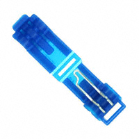
Fig.1
For 22-16 AWG wires, refer to Fig. 1
1. Insert the correct size wire properly into the connector.
2. Position the connector into the tongue-and-groove pliers as shown
and carefully squeeze until the latch engages.
Fig.1
For 22-16 AWG wires, refer to Fig. 1
1. Insert the correct size wire properly into the connector.
2. Position the connector into the tongue-and-groove pliers as shown
and carefully squeeze until the latch engages.
For 14-12 AWG wires, refer to Fig. 2, 3, and 1.
1. Bend the wire support membranes outward with wire (Fig.2)
2. Place the correct size wire into the nest of the metal and gently
squeeze the wire into position with tongue-and-groove pliers without
distorting (flattening) the wire insulation (Fig.3).
3. Position the connector into the tongue-and-groove pliers as shown
and carefully squeeze until the latch engages (Fig.1).
Fig. 2
Fig. 2
Fig. 3
Bend membranes with wire
Bend membranes with wire
Lit p/n 192160127, rev B
4650 62nd Avenue N
Pinellas Park, FL
33781
Lit p/n 192160127, rev B
UL file E79133 Vol 1, Sec 2
CSA file LR18689 class 6223-02
Wire Range
22-18 AWG
18-14 AWG
12 AWG
For use with only stranded
copper wire and
copper alloy tabs
600V, 105°C
4650 62nd Avenue N
Pinellas Park, FL
33781
UL file E79133 Vol 1, Sec 2
CSA file LR18689 class 6223-02
Assembly Instructions for Wire Tap Splices
Assembly Instructions for Wire Tap Splices
Engineering P/N
WT-2218
WT-1814
WT-12
Fig. 3
NOTICE
OPTIMAL STORAGE CONDITION
Store in climate controlled environment
23-25°C (73-77°F)
50% minimum relative humidity
Engineering P/N
WT-2218
WT-1814
WT-12
Wire Range
22-18 AWG
18-14 AWG
12 AWG
For use with only stranded
copper wire and
copper alloy tabs
600V, 105°C
NOTICE
OPTIMAL STORAGE CONDITION
Store in climate controlled environment
23-25°C (73-77°F)
50% minimum relative humidity
Fig.1
For 22-16 AWG wires, refer to Fig. 1
1. Insert the correct size wire properly into the connector.
2. Position the connector into the tongue-and-groove pliers as shown
and carefully squeeze until the latch engages.
Fig.1
For 22-16 AWG wires, refer to Fig. 1
1. Insert the correct size wire properly into the connector.
2. Position the connector into the tongue-and-groove pliers as shown
and carefully squeeze until the latch engages.
For 14-12 AWG wires, refer to Fig. 2, 3, and 1.
1. Bend the wire support membranes outward with wire (Fig.2)
2. Place the correct size wire into the nest of the metal and gently
squeeze the wire into position with tongue-and-groove pliers without
distorting (flattening) the wire insulation (Fig.3).
3. Position the connector into the tongue-and-groove pliers as shown
and carefully squeeze until the latch engages (Fig.1).
Fig. 2
Fig. 2
Fig. 3
Fig. 3
Bend membranes with wire
Bend membranes with wire
Lit p/n 192160127, rev B
Lit p/n 192160127, rev B
nd
4650 62 Avenue N
Pinellas Park, FL
33781
UL file E79133 Vol 1, Sec 2
CSA file LR18689 class 6223-02
4650 62nd Avenue N
Pinellas Park, FL
33781
UL file E79133 Vol 1, Sec 2
CSA file LR18689 class 6223-02
�
很抱歉,暂时无法提供与“19216-0010”相匹配的价格&库存,您可以联系我们找货
免费人工找货- 国内价格 香港价格
- 161+2.14053161+0.26555


 工商网监
湘ICP备2023018690号
工商网监
湘ICP备2023018690号

