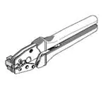
Hand Crimp Tool
HAND CRIMP TOOL
SPECIFICATION SHEET
Order No. 63811-3300
(Replaces 11-01-0008
HTR1719C)
TYPE 2C
FEATURES
�
�
�
�
A full cycle ratcheting hand tool ensures complete crimps
Ergonomic soft grip handles for comfortable crimping
A precision user-friendly terminal locator wire stop holds terminals in the proper crimping position
This tool is IPC/WHMA-A-620 Class 2 and RoHS compliant
SCOPE
Products: .1.57mm (.062") Diameter, Standard .062" Pin and Socket Crimp Terminal, 18-24 AWG.
KK® Crimp Terminal, Flat Blade Crimp Terminal, and
4.80mm (.189") Pitch Crimp Terminal, 18-24 AWG.
Terminal
Series No.
1560
1561
1786
1787
1799
1943
4529
5005
5006
6770
6772
Terminal Order No.
Loose Piece
Reel
02-06-2103 02-06-6119 02-06-2101 02-06-6118
02-06-6102 04-01-0807 02-06-6100 04-01-0805
02-06-6103 39-00-0327 02-06-6101 39-00-0328
02-06-6104 39-00-0330 02-06-6105 39-00-0329
02-06-6112
02-06-6116 39-00-0378
02-06-1103 04-01-0808 02-06-1101 02-06-5108
02-06-5102 39-00-0331 02-06-1118 04-01-0806
02-06-5103 39-00-0334 02-06-5100 39-00-0279
02-06-5104
02-06-5101 39-00-0333
02-06-5109
02-06-5105
02-06-2202 02-06-6206 02-06-2201 02-06-6205
02-06-6202 02-06-6212 02-06-6201 02-06-6211
02-06-1202 02-06-5202 02-06-1201 02-06-5201
02-06-3201 02-06-5206 02-06-3200 02-06-5205
08-30-0110 08-34-0110 08-30-0109 08-34-0109
08-34-0106 08-35-0106 08-34-0105 08-35-0105
08-34-0108
08-34-0107
05-06-0201 05-06-0206 05-06-0200 05-16-0200
05-06-0204
05-06-0205 05-16-0201
05-06-0203
05-06-0211
02-06-1105 02-06-5208 02-06-1104 02-06-5207
02-06-5118 02-06-5218 02-06-5117
08-70-0042 39-00-0014 08-70-0001 39-00-0013
08-70-1012
08-70-1011
08-70-0043 39-00-0016 08-70-0002 39-00-0015
08-70-1014
08-70-1013
02-06-5142
02-06-6140
Doc No: ATS- 638113300
Revision: C
�
Release Date: 11-19-03
Revision Date: 03-28-08
Wire Size
AWG
mm²
�Insulation Diameter
mm
In.
Strip Length
mm
In.
18-24 0.82-0.20
1.52-3.05
.060-.120
2.41-3.04 .095-.120
18-24 0.82-0.20
1.52-3.05
.060-.120
2.41-3.04 .095-.120
18-24 0.82-0.20
1.52-3.05
.060-.120
2.41-3.04 .095-.120
18-24 0.82-0.20
1.52-3.05
.060-.120
2.41-3.04 .095-.120
18-24 0.82-0.20
1.52-3.05
.060-.120
2.41-3.04 .095-.120
18-24 0.82-0.20
1.52-2.79
.060-.110
2.41-3.04 .095-.120
18-24 0.82-0.20
1.52-3.05
.060-.120
2.41-3.04 .095-.120
18-24 0.82-0.20
1.30-3.00
.051-.118
2.30-2.95 .090-.116
18-24 0.82-0.20
1.30-3.00
.051-.118
2.30-2.95 .090-.116
18-24 0.82-0.20
18-24 0.82-0.20
1.52-3.05
1.52-3.05
.060-.120
.060-.120
2.41-3.04 .095-.120
2.41-3.04 .095-.120
UNCONTROLLED COPY
Page 1 of 8
�Hand Crimp Tool
�
Terminal
Terminal Order No.
Wire Size
Insulation Diameter
Strip Length
Series No.
Loose Piece
Reel
AWG
mm²
mm
In.
mm
In.
7291
02-06-1139
18-24 0.82-0.20 1.52-3.05 .060-.120 2.41-3.04 .095-.120
8662
16-02-0050
16-02-0049
18-24 0.82-0.20 1.52-2.79 .060-.110 2.41-3.04 .095-.120
8960
16-02-0053
18-24 0.82-0.20 1.52-2.79 .060-.110 2.41-3.04 .095-.120
Follow the Cut-Off Tab specifications on Applicator specification sheets.
See Conditions on page 2.
�
�
�
DEFINITION OF TERMS
BEND UP
BRUSH
BELL MOUTH
CONDUCTOR
CRIMP
INSULATION
CRIMP
ROLLING
TWISTING
STRIP
LENGTH
BEND
DOWN
CRIMP HEIGHT
The above terminal drawing is a generic terminal representation. It is not an image of a terminal listed in the
scope.
CONDITIONS:
After crimping, the conductor profiles should measure the following (see notes on page 5).
Terminal Hand Tool Wire Size
Series No. Locator
AWG mm2
1
18 0.82
1
20 0.52
1560
1
22 0.32
1
24 0.20
1
18 0.82
1
20 0.52
1561
1
22 0.32
1
24 0.20
1
18 0.82
1
20 0.52
1786
1
22 0.32
1
24 0.20
1
18 0.82
1
20 0.52
1787
1
22 0.32
1
24 0.20
1799
2
18 0.82
2
20 0.52
2
22 0.32
Doc No: ATS- 638113300
Revision: C
Conductor Crimp
Conductor
Height (REF)
Crimp Width (Ref)
mm
In.
mm
In.
1.02-1.12 .040-.044 1.95
.077
0.87-0.97 .034-.038 1.95
.077
0.87-0.97 .034-.038 1.95
.077
0.87-0.97 .034-.038 1.95
.077
1.02-1.12 .040-.044 1.95
.077
0.87-0.97 .034-.038 1.95
.077
0.87-0.97 .034-.038 1.95
.077
0.87-0.97 .034-.038 1.95
.077
1.02-1.12 .040-.044 1.95
.077
0.87-0.97 .034-.038 1.95
.077
0.87-0.97 .034-.038 1.95
.077
0.87-0.97 .034-.038 1.95
.077
1.02-1.12 .040-.044 1.95
.077
0.87-0.97 .034-.038 1.95
.077
0.87-0.97 .034-.038 1.95
.077
0.87-0.97 .034-.038 1.95
.077
1.02-1.12 .040-.044 1.95
.077
0.87-0.97 .034-.038 1.95
.077
0.87-0.97 .034-.038 1.95
.077
Release Date: 11-19-03
Revision Date: 03-28-08
Pull Force
Minimum
N Lb.
89.0 20.00
66.8 15.00
44.5 10.00
35.6 8.00
89.0 20.00
66.8 15.00
44.5 10.00
35.6 8.00
89.0 20.00
66.8 15.00
44.5 10.00
35.6 8.00
89.0 20.00
66.8 15.00
44.5 10.00
35.6 8.00
111.3 25.00
66.8 15.00
53.4 12.00
UNCONTROLLED COPY
Profile
A
X
B
X
X
X
X
X
X
X
X
X
X
X
X
X
X
X
X
X
X
Page 2 of 8
�Hand Crimp Tool
Terminal Hand Tool Wire Size
Series No. Locator
AWG mm2
2
24 0.20
1
18 0.82
1
20 0.52
1943
1
22 0.32
1
24 0.20
1
18 0.82
1
20 0.52
4529
1
22 0.32
1
24 0.20
1
18 0.82
1
20 0.52
5005
1
22 0.32
1
24 0.20
1
18 0.82
1
20 0.52
5006
1
22 0.32
1
24 0.20
1
18 0.82
1
20 0.52
6770
1
22 0.32
1
24 0.20
1
18 0.82
1
20 0.52
6772
1
22 0.32
1
24 0.20
1
18 0.82
1
20 0.52
7291
1
22 0.32
1
24 0.20
1
18 0.82
1
20 0.52
8662
1
22 0.32
1
24 0.20
1
18 0.82
1
20 0.52
8960
1
22 0.32
1
24 0.20
Conductor Crimp
Conductor
Height (REF)
Crimp Width (Ref)
mm
In.
mm
In.
0.87-0.97 .034-.038 1.95
.077
1.02-1.12 .040-.044 1.95
.077
0.87-0.97 .034-.038 1.95
.077
0.87-0.97 .034-.038 1.95
.077
0.87-0.97 .034-.038 1.95
.077
1.02-1.12 .040-.044 1.95
.077
0.87-0.97 .034-.038 1.95
.077
0.87-0.97 .034-.038 1.95
.077
0.87-0.97 .034-.038 1.95
.077
1.02-1.12 .040-.044 1.95
.077
0.87-0.97 .034-.038 1.95
.077
0.87-0.97 .034-.038 1.95
.077
0.87-0.97 .034-.038 1.95
.077
1.02-1.12 .040-.044 1.95
.077
0.87-0.97 .034-.038 1.95
.077
0.87-0.97 .034-.038 1.95
.077
0.87-0.97 .034-.038 1.95
.077
1.02-1.12 .040-.044 1.95
.077
0.87-0.97 .034-.038 1.95
.077
0.87-0.97 .034-.038 1.95
.077
0.87-0.97 .034-.038 1.95
.077
1.02-1.12 .040-.044 1.95
.077
0.87-0.97 .034-.038 1.95
.077
0.87-0.97 .034-.038 1.95
.077
0.87-0.97 .034-.038 1.95
.077
1.02-1.12 .040-.044 1.95
.077
0.87-0.97 .034-.038 1.95
.077
0.87-0.97 .034-.038 1.95
.077
0.87-0.97 .034-.038 1.95
.077
1.02-1.12 .040-.044 1.95
.077
0.87-0.97 .034-.038 1.95
.077
0.87-0.97 .034-.038 1.95
.077
0.87-0.97 .034-.038 1.95
.077
1.02-1.12 .040-.044 1.95
.077
0.87-0.97 .034-.038 1.95
.077
0.87-0.97 .034-.038 1.95
.077
0.87-0.97 .034-.038 1.95
.077
Pull Force
Minimum
N Lb.
35.6 8.00
111.3 25.00
66.8 15.00
53.4 12.00
35.6 8.00
89.0 20.00
66.8 15.00
44.5 10.00
35.6 8.00
98.0 22.00
66.8 15.00
53.4 12.00
35.6 8.00
98.0 22.00
66.8 15.00
53.4 12.00
35.6 8.00
89.0 20.00
66.8 15.00
44.5 10.00
35.6 8.00
89.0 20.00
66.8 15.00
44.5 10.00
35.6 8.00
89.0 20.00
66.8 15.00
44.5 10.00
35.6 8.00
111.3 25.00
66.8 15.00
44.5 10.00
31.4 7.00
111.3 25.00
66.8 15.00
44.5 10.00
31.4 7.00
Profile
A
B
X
X
X
X
X
X
X
X
X
X
X
X
X
X
X
X
X
X
X
X
X
X
X
X
X
X
X
X
X
X
X
X
X
X
X
X
X
JAWS OPEN
OPERATION
CAUTION: Install only Molex terminals listed above with this tool.
Do not crimp hardened objects damage can occur to the tool or die.
LOCATOR
Open the tool by squeezing the handles together, at the end of the
closing stroke, the ratchet mechanism will release the handles, and
the hand tool will spring open.
Figure 1
Doc No: ATS- 638113300
Revision: C
Release Date: 11-19-03
Revision Date: 03-28-08
UNCONTROLLED COPY
Page 3 of 8
�Hand Crimp Tool
Crimping Terminals
1. Select the desired terminal listed in the preceding charts. Make sure that the proper locator is mounted on the
tool.
2. Swing the terminal locator away from the crimp tool shown in Figure 2. Some terminals with large insulation
grips may interfere with the crimp tooling when swinging the locator into position. The terminal must then be
loaded into the locator in the closed/crimp position.
TERMINAL
SWING OPEN
PUSH HERE TO
OPEN WIRE STOP
LOCATOR
LOCATOR
Figure 2
3. When using 63811-3275 (Locator No. 1), press down on the
wire stop on the locator as shown in Figure 2. Insert the
proper terminal into the proper nest opening. Make sure when
choosing the nest opening, it will correspond with the A or B
profile on the hand tool.
4. Return the locator to its original position.
5. Insert the proper wire over the terminal. Gently touch the wire
stop with the end of the wire. See Figure 3.
6. Compress the terminal by squeezing the tool handles until the
ratchet mechanism cycle has been completed. Release
handles to open the jaws.
TERMINAL
IN PLACE
WIRE STOP
WIRE
LOCATOR
IN PLACE
TERMINAL
Note: The tamper proof ratchet action will not release the tool until
it has been fully closed.
7. Remove the crimp terminal from the terminal locator by
pressing down on the wire stop and gently pulling on the wire.
The terminal locator can by in either position
8. Visually inspect the crimped terminal for proper crimp location
and crimp height.
Doc No: ATS- 638113300
Revision: C
Release Date: 11-19-03
Revision Date: 03-28-08
WIRE STOP
WIRE
AGAINST STOP
UNCONTROLLED COPY
Figure 3
Page 4 of 8
�Hand Crimp Tool
TERMINAL FLUSH WITH
INSULATION TOOLING
✴ Crimping Terminals without a Locator
1. With the hand tool in the open position, select the proper profile.
2. Position the terminal in the proper profile; partially close the hand
tool until the terminal is held in place. The terminal should be
positioned so that the front of the insulation grips is flush with the
front face of the insulation tooling. See Figure 3A.
INSULATION TOOLING
3. Gently slip the wire into the terminal, and then position the
Figure 3A
insulation and stripped strands into the terminal insulation and
conductor grips. Note: No wire stop is provided. If the wire will not fit into the partially closed tool, due to large
insulation diameter, the terminal and wire must then be placed in the open tool. Applying slight downward
pressure on the wire may help hold the terminal in place while crimping.
4. Compress the terminal by squeezing the tool handles until the ratchet mechanism cycle has been completed.
Release handles to open the jaws.
Note:
A crimp height chart is provided with this manual as Reference Only. Due to the wide range of wires, strands,
insulation diameters, and durometers, actual crimp height measurements may very slightly. An occasional,
destructive, pull force test should be preformed to check hand tool crimp. Pull Force value Must exceed the
Minimum pull force specifications listed on pages 2 and 3.
LIFT UP
LOCATOR
Locator Change Over
Two styles of locators are provided with the crimp hand
tool 63811-3300. They are locator no. 1 (63811-3375),
which is black and locator no.2 (63811-3376), which is
gray. Make sure the desired style of locator is installed
for the proper terminal and wire. Follow the steps below
to change the locators.
1. Open the crimp hand tool.
2. Swing the existing locator open and away from the
hand tool.
3. Firmly press down on the brass pivot shaft with your
thumb, while pulling the locator up. Slip the locator
off the top of the brass pivot shaft. See Figure 4.
4. Replace it with the desired locator by putting over
the brass pivot shaft and snapping it into place.
JAWS
OPEN
PRESS DOWN ON
BRASS PIVOT SHAFT
SWING
LOCATOR
OPEN
Figure 4
Maintenance
It is recommended that each operator of the tool be made aware of, and responsible for, the following
maintenance steps:
Doc No: ATS- 638113300
Revision: C
Release Date: 11-19-03
Revision Date: 03-28-08
UNCONTROLLED COPY
Page 5 of 8
�Hand Crimp Tool
1. Remove dust, moisture, and other contaminants with a clean brush, or soft, lint free cloth.
2. Do not use any abrasive materials that could damage
the tool.
3. Make certain all pins; pivot points and bearing surfaces
LUBRICATION POINTS
(BOTH SIDES) LIGHT OIL
are protected with a thin coat of high quality machine
(EVERY 3 MONTHS OR
oil. Do not oil excessively. The 63811-3300 was
5,000 CRIMPS)
engineered for durability but like any fine piece of
equipment it needs cleaning and lubrication for a
maximum service life of trouble free crimping. Light oil
such as 30 weights automotive oil used at the oil points
shown in Figure 6, every 5,000 crimps or 3 months, will
significantly enhance the tool life.
4. Wipe excess oil from hand tool, particularly from
crimping area. Oil transferred from the crimping area
Figure 5
onto certain terminations may affect the electrical
characteristics of an application.
5. When tool is not in use, keep the handles closed to prevent objects from becoming lodged in the crimping
dies, and store the tool in a clean, dry area.
Miscrimps or Jams
Should this tool ever become stuck or jammed in a partially closed position, Do Not force the handles open or
closed. The tool will open easily by pressing the ratchet release lever (See Figure 6).
How To Adjust Tool Preload
(See Figure 6)
This hand tool is factory preset to 25-45 LBS.
preload. It may be necessary over the life of the
tool to adjust tool handle preload force. Listed
below are the steps required to adjust the crimping
force of the hand tool to obtain proper crimp
conditions:
PRELOAD
CHECK POINT
25.4MM
SETTING WHEEL
ECCENTRIC AXLE
HANDLE
GRIP
REMOVED
1. Remove or fold back the handle grip from the
handle to expose the eccentric axle counter.
2. Remove the locking screw. The wrench set
WRENCH SET
(63810-0101), is not supplied. It is sold
LOCKING
HANDLE
(SOLD
separately from the hand tool. See our
GRIP
SEPERATELY) SCREW
website or contact your sales engineer.
3. Turning the eccentric axle counter-clockwise (CCW) will increase handle force.
4. Replace the locking screw, aligning the nearest notch in the setting wheel to locking screw.
5. Replace the handle grip.
6. Check the crimp specifications after tool handle preload force is adjusted.
Doc No: ATS- 638113300
Revision: C
Release Date: 11-19-03
Revision Date: 03-28-08
UNCONTROLLED COPY
RATCHET
RELEASE LEVER
Figure 6
Page 6 of 8
�Hand Crimp Tool
Warranty
This tool is for electrical terminal crimping purposes only. This tool is made of the best quality materials. All vital
components are long life tested. All tools are warranted to be free of manufacturing defects for a period of 30
days. Should such a defect occur, we will repair or exchange the tool free of charge. This repair or exchange will
not be applicable to altered, misused, or damaged tools. This tool is designed for hand use only. Any clamping,
fixturing, or use of handle extensions voids this warranty.
CAUTION: Molex crimp specifications are valid only when used with Molex terminals, applicators and
tooling.
CAUTIONS
1. Manually powered hand tools are intended for low volume or field repair. This tool is NOT intended for
production use. Repetitive use of this tool should be avoided.
2. Insulated rubber handles are not protection against electrical shock.
3. Wear eye protection at all times.
4. Use only Molex Terminal specified for crimping with the tool.
Certification
Molex does not certify or re-certify commercial grade hand tools but rather supplies the following guidelines for
customers to re-certify hand tools.
% This tool is qualified to pull force only. To re-certify, crimp a terminal to a wire, which has been stripped
12.7mm (1/2”) long, so there is no crimping of the insulation. Pull the terminal and wire at a rate no faster than
25mm (1.00”) per minute. See the Molex web site for the Quality Crimp Handbook for more information on pull
testing.
% If the tool does not meet minimum pull force values, handle preload should be increased and the pull test
rerun, (See How to Adjust Preload).
% When the hand tool is no longer capable of achieving minimum pull force, it should be taken out of service and
replaced.
Doc No: ATS- 638113300
Revision: C
Release Date: 11-19-03
Revision Date: 03-28-08
UNCONTROLLED COPY
Page 7 of 8
�Hand Crimp Tool
PARTS LIST
Item Number
1
2
3
4
5
Order Number
63810-0101
63810-0102
63810-0103
63811-3375
63811-3376
Description
Wrench Set (Not included)
Locator Base Assembly
Repair Kit (Not included)
Locator #1-Black
Locator #2-Gray
Quantity
0
1
0
1
1
5
1
3
4
M4 X 5LG
BHCS
RATCHET
RELEASE LEVER
2
3
Figure 7
Americas Headquarters
Lisle, Illinois 60532 U.S.A.
1-800-78MOLEX
amerinfo@molex.com
Far East North Headquarters
Yamato, Kanagawa, Japan
81-462-65-2324
feninfo@molex.com
Far East South Headquarters
Jurong, Singapore
65-6-268-6868
fesinfo@molex.com
European Headquarters
Munich, Germany
49-89-413092-0
eurinfo@molex.com
Corporate Headquarters
2222 Wellington Ct.
Lisle, IL 60532 U.S.A.
630-969-4550
Fax: 630-969-1352
Visit our Web site at http://www.molex.com
Doc No: ATS- 638113300
Revision: C
Release Date: 11-19-03
Revision Date: 03-28-08
UNCONTROLLED COPY
Page 8 of 8
�