C1U-W-1200-48-Tx Series
www.murata-ps.com
AC/DC Front End Power Supply
PRODUCT OVERVIEW
The C1U-W-1200 is a 1200 Watt universal AC input, power-factor-corrected (PFC) front-end power
supply for general applications. The main output is 48V with a standby output of either 5V, 3.3V, or 12V.
Packaged in a 1U low profile chassis, it is designed to deliver reliable bulk power to servers, workstations, storage systems or any 48V distributed power architecture systems requiring high power density.
The highly efficient electrical and thermal design with internal cooling fans supports reliable operation
conditions. The C1U-W-1200 is designed to autorecover from overtemperature faults.
FEATURES
SELECTION GUIDE
1200W (110/220Vac) Output power
Part Number
48V Main output,
3.3V, 5V or 12V standby output
Dimensions: 5.5" x 14.2" x 1.67"
9.2 Watts per cubic inch density
N+1 redundancy capable (up to 3 in parallel)
Active current sharing on main output
Overvoltage, overcurrent,
overtemperature protection
Internal cooling fans
RoHS compliant
Power Output
Universal Line
Main Output
Standby
Output
Airflow
1200W
1200W
1200W
1200W
1200W
1200W
48V
48V
48V
48V
48V
48V
5V
3.3V
5V
3.3V
12V
12V
Front to back
Front to back
Back to front
Back to front
Front to back
Back to front
C1U-W-1200-48-TA1C
C1U-W-1200-48-TC1C
C1U-W-1200-48-TA2C
C1U-W-1200-48-TC2C
C1U-W-1200-48-TB1C
C1U-W-1200-48-TB2C
INPUT CHARACTERISTICS
Parameter
Conditions
Min.
Typ.
Max.
Units
Input Voltage Operating Range
Input Frequency
Turn-on Input Voltage
Turn-off Input Voltage
Maximum Input Current
Inrush Current
115/230
55
264
63
86.5
78
15
90
Vac
Hz
Ramp up
Ramp down
90
47
78.5
70.5
Power Factor
Output load >90%
Output load >50%
Vac
Arms
Apk
95%
75%
OUTPUT VOLTAGE CHARACTERISTICS
Output
Voltage
48V
3.3Vsb
5Vsb
12Vsb
Parameter
Voltage Set Point Accuracy
Line and Load Regulation
Ripple Voltage & Noise1
Output Current
Load Capacitance
Voltage Set Point Accuracy
Line and Load Regulation
Ripple Voltage & Noise1
Operating Range
Load Capacitance
Voltage Set Point Accuracy
Line and Load Regulation
Ripple Voltage & Noise1
Operating Range
Load Capacitance
Voltage Set Point Accuracy
Line and Load Regulation
Ripple Voltage & Noise1
Operating Range
Load Capacitance
Conditions
Min.
Typ.
Max.
Units
49.44
480
24.6
10000
mV p-p
A
μF
48
46.54
20MHz Bandwidth
2
3.3
3.2
3.4
50
4.5
1530
20MHz Bandwidth
0
5
4.85
5.15
50
4
1530
20MHz Bandwidth
0
12
11.2
20MHz Bandwidth
0
12.4
120
1.7
1530
Vdc
Vdc
mV p-p
A
μF
Vdc
mV p-p
A
μF
Vdc
mV p-p
A
μF
1
Ripple and noise are measured with 0.1 uF of ceramic capacitance and 10 uF of tantalum capacitance on each of
the power supply outputs. A short coaxial cable with 50ohm scope termination is used.
For full details go to
www.murata-ps.com/rohs
www.murata-ps.com/support
CPS_C1U-W-1200-48-Tx.B02 Page 1 of 5
�C1U-W-1200-48-Tx Series
AC/DC Front End Power Supply
OUTPUT CHARACTERISTICS
Parameter
Conditions
Remote Sense
Efficiency
Output Rise Monotonicity
Startup Time
Transient Response
Current sharing accuracy (up to 3 in parallel)
Min.
Typ.
Max.
Compensates for up to 0.12V of lead drop
120
with or without remote sense connected
220Vac
90.6
Overshoot less than 10% for all outputs, no voltage negative between 10% to 95% during ramp up
AC ramp up
1.5
PS_On activated
150
48V Ramp 1A/μs
±600
3.3Vsb Ramp 1A/μs
±165
5Vsb Ramp 1A/μs
±250
12Vsb Ramp 1A/μs
At 100% load
Holdup Time
±10
20
Units
mV
%
s
ms
mV
%
ms
ENVIRONMENTAL CHARACTERISTICS
Parameter
Conditions
Min.
Storage Temperature Range
Operating Temperature Range
Operating Humidity
Storage Humidity
Shock
Sinusoidal Vibration
Non-condensing
-40
0
10
5
MTBF
Safety Approvals
Non-condensing
Typ.
Max.
70
50
90
90
30G non operating
0.5G, 5 – 500 Hz
Telcordia SR-332 @ 30°C
200K
Demonstrated
200K
CAN/CSA C22.2 No. 60950-1-07, 2nd Ed.
UL 60950-1, 2nd Ed.
IEC 60950-1:2005 (2nd Edition); EN 60950-1:2006 +A11
Units
°C
%
hrs
hrs
Input Fuse
Material Flammability
Power Supply has internal 20A/250V fast blow fuse on the AC line input
UL 94V-0
Switching Frequency
90KHz for Boost PFC Converter
165KHz for Main Output Converter
200KHz for Standby Output Converter
Weight
5.7 lbs (2.6kg)
PROTECTION CHARACTERISTICS
Output
Voltage
48V
3.3Vsb
5Vsb
12Vsb
Parameter
Conditions
Min.
Overtemperature
Overvoltage
Overcurrent
Overvoltage
Overcurrent
Overvoltage
Overcurrent
Overvoltage
Overcurrent
Autorestart
Latching
Latching
Latching
Latching
Latching
Latching
Latching
Latching
55
54
26
3.57
6.5
5.6
5
13
2.5
Conditions
Min.
Typ.
Max.
Units
65
59
35
4.02
8
6
7
14
3
°C
V
A
V
A
V
A
V
A
Max.
Units
ISOLATION CHARACTERISTICS
Parameter
Insulation Safety Rating / Test Voltage
Isolation
Grounding
Typ.
Input to Output - Reinforced
3000
Vrms
Input to Chassis - Basic
1500
Vrms
Output to Chassis
Output to Output
Main Output Return and Standby Output Return are connected internally. 100kΩ resistor parallel with 100nF
capacitor is connected between Return and power supply chassis. Main Output Return should be connected to
the System Chassis.
www.murata-ps.com/support
CPS_C1U-W-1200-48-Tx.B02 Page 2 of 5
�C1U-W-1200-48-Tx Series
AC/DC Front End Power Supply
STATUS INDICATORS AND CONTROL SIGNALS
Status
Conditions
Description
LED
Off
Flashing Yellow
Flashing Green
Green
PS_ON
To enable main output
No AC input to all PS
Power Supply Failure
Main Output Absent
Power Supply Good
Short PS_ON to GND (required)
Short SENSE+ to 48 main at point of load (optional for better regulation)
Short SENSE- to Output GND at point of load (optional for better regulation)
EMISSIONS AND IMMUNITY
Characteristic
Standard
Compliance
Input Current Harmonics
Voltage Fluctuation and Flicker
Conducted Emissions
Radiated Emissions
IEC/EN 61000-3-2
IEC/EN 61000-3-3
FCC 47 CFR Part 15/CISPR 22/EN55022
FCC 47 CFR Part 15/CISPR 22/EN55022
ESD Immunity
IEC/EN 61000-4-2
Radiated Field Immunity
Electrical Fast Transients/Burst Immunity
Surge Immunity
RF Conducted Immunity
Magnetic Field Immunity
Voltage Dips, Interruptions
IEC/EN 61000-4-3
IEC/EN 61000-4-4
IEC/EN 61000-4-5
IEC/EN 61000-4-6
IEC/EN 61000-4-8
IEC/EN 61000-4-11
Complies
Complies
Class A, 6dB margin
Class A, 6dB margin
4kV contact discharge
8kV operational air discharge
15kV non-operational air discharge
Complies
Complies
1kV/2kV, Performance Criteria B
3 Vac, 80% AM, 1kHz, Performance Criteria A
3 A/m
Complies
www.murata-ps.com/support
CPS_C1U-W-1200-48-Tx.B02 Page 3 of 5
�C1U-W-1200-48-Tx Series
AC/DC Front End Power Supply
WIRING DIAGRAM FOR OUTPUT
Dotted lines show optional remote sense connections.
Optional remote sense lines can be attached to a load that is a distance
away from the power supply to improve regulation at the load.
SENSE+
SENSE+
7
48V Main
48V Main
+ STUD
+ STUD
7
C1U
48V load
C1U
- STUD
Output GND
Output GND
8
5
9, 10, 11, 12
3
SENSE-
SENSE-
ISHARE
ISHARE
V_SB
V_SB
PS_ON
PS_ON
Close switch (or FET, BJT, or wire)
to turn on 12V Main
13, 14, 15, 16
- STUD
8
5
9, 10, 11, 12
3
+3.3 or +5V
logic circuitry
GND
GND
C
R
100k 100nF
13, 14, 15, 16
C1
R1
100k 100nF
CURRENT SHARING NOTES
Main Output: Current sharing is achieved using the active current share method. (See wiring diagram for connection details.)
The total combined load must be below 1200W at startup. Current sharing can be achieved with or without remote sense connected to the common load.
V_SB outputs can be tied together for redundancy but total combined output power must not exceed 20W. The V_SB output has internal ORing MOSFET for
additional redundancy / internal short protection.
The current share pin 5 is a connection between the two units. It is input and/or output as the voltage on the line controls the current share. A power
supply will respond to a change in this voltage but a power supply can also change the voltage depending on the load drawn from it. On a single unit this
would read 8V at 100% load. For two units sharing load then this should read 4V for perfect current sharing.
Up to 3 units can be paralleled together. Please consult your Murata sales representative if operation with more than three units in parallel is needed.
www.murata-ps.com/support
CPS_C1U-W-1200-48-Tx.B02 Page 4 of 5
�C1U-W-1200-48-Tx Series
AC/DC Front End Power Supply
5.500
(139.70)
MECHANICAL DIMENSIONS
AC Input
Terminal Block
15.197 REF
(386.00)
M4 Ground Stud
1.673
(42.50)
14.220
(361.20)
Signal Connector
Output Terminal
M5 Studs
5.000
(127.00)
M4 Mounting Thread
(4X)
4.803
(122.00)
4.847
(123.12)
Dimensions: 5.5 " x 14.2" x 1.67" [139.7mm x 361.2mm x 42.5mm]
CONNECTORS
Signal 16 pin connector details, Type: TE Connectivity
(Tyco) 281281-1 Mating part 1658622-3
Pin
Signal
1
AC_OK
2
P_GOOD
3
PS_ON
4
BLANK
5
I_SHARE
6
BLANK
7
SENSE+
8
SENSE9
V_SB
10
V_SB
11
V_SB
12
V_SB
13
GND
14
GND
15
GND
16
GND
2-Pole terminal Block for AC Line and Neutral
Stud on Chassis for earth
+
48V Main
Output GND
Murata Power Solutions, Inc.
11 Cabot Boulevard, Mansfield, MA 02048-1151 U.S.A.
ISO 9001 and 14001 REGISTERED
Front View
Pin 1
Pin 2
Signal
Connector
Output Terminal
M5 Studs
This product is subject to the following operating requirements
and the Life and Safety Critical Application Sales Policy:
Refer to: http://www.murata-ps.com/requirements/
Murata Power Solutions, Inc. makes no representation that the use of its products in the circuits described herein, or the use of other
technical information contained herein, will not infringe upon existing or future patent rights. The descriptions contained herein do not imply
the granting of licenses to make, use, or sell equipment constructed in accordance therewith. Specifi cations are subject to change
without notice.
© 2017 Murata Power Solutions Inc.
www.murata-ps.com/support
CPS_C1U-W-1200-48-Tx.B02 Page 5 of 5
�
很抱歉,暂时无法提供与“C1U-W-1200-48-TB2C”相匹配的价格&库存,您可以联系我们找货
免费人工找货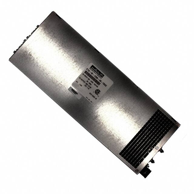


 工商网监
湘ICP备2023018690号
工商网监
湘ICP备2023018690号
