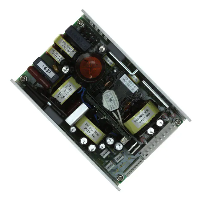
CF200-A12C
200 Watt High Density AC/DC Power Supply
SELECTION GUIDE
Model Number
CF200-A12C
Power Output
200W
Main Output
12V
Auxilliary Output
5V
INPUT CHARACTERISTICS
Parameter
Input Voltage Operating Range Input Frequency Turn-on Input Voltage Turn-off Input Voltage Maximum Rated Input Current Inrush Current Power Factor
Conditions
Min.
85 47
Typ.
Max.
264 63
Units
Vac Hz Vac
FEATURES
200W compact high density Active load current share Universal AC input with Power Factor Correction Ruggedized U-channel construction RoHS compliant Includes ORing diode for N+1 parallel operation International regulatory approvals
Ramp up Ramp down 100Vac Cold start at 25°C, 115Vac Cold start at 25°C, 230Vac
75 65 2.8 25 50 96 98
Arms Apk %
230Vac, full load 115Vac, full load
OUTPUT VOLTAGE CHARACTERISTICS
Output Voltage Parameter
Voltage Set Point Accuracy Line and Load Regulation 12V Ripple Voltage & Noise1 Output Current Peak Current Voltage Set Point Accuracy Line and Load Regulation Output Current Ripple Voltage & Noise1
Conditions
±1% tolerance 20MHz Bandwidth
Min.
Typ.
12.2
Max.
±1 150
Units
Vdc % mV p-p A Vdc % mA mV p-p
0 17 5 ±2 0 20MHz Bandwidth
16.6
DESCRIPTION
The CF200-A12C switching power supply utilizes advanced component and circuit technologies to deliver one of the industry’s smallest 200 Watt switchers. Built to meet 1U height considerations, the U-Frame package measures only 3.30 x 5.00 x 1.50”. The CF200-A12C offers universal AC input (85-265VAC) with active power factor correction (PFC) and compliance to worldwide safety and EMC standards.
5Vaux
5 100
OUTPUT CHARACTERISTICS
Parameter
Remote Sense
Conditions
Min.
Typ.
Max.
Units
Compensates for voltage drops of up to 0.5V between the power supply to the load. Outputs are internally sensed at output connector if remote sense lines are opened. 230Vac, full load 115Vac, full load Output voltage at 90% For load change of 25% to 75%, at slew rate of 1A/μs, recovery time less than 2ms Single wire current share in a N+1 parallel redundant configuration with OR-ng diodes included in the PSU Available 110Vac, full load Voltage change at turn-on and turn-off 16 1 86 82 2.0 20 ±5 % s ms %
Efficiency Start-up Delay Rise Time Transient Load Response
Current Sharing Accuracy Hot Swap Hold-up Time Overshoot and Undershoot
±10
%
ms %
1 Ripple and noise are measured with 10 μF, in parallel with 0.1 μF ceramic capacitors.
www.murata-ps.com
Technical enquiries email: toronto@murata-ps.com, tel: +1 (866) 740 1232
CF200-A12C.A01 Page 1 of 4
�CF200-A12C
200 Watt High Density AC/DC Power Supply
GENERAL CHARACTERISTICS
Parameter
Storage Temperature Range Operating Temperature Range Temperature Coefficient Cooling Operating Humidity Storage Humidity Altitude Vibration
Conditions
Min.
Typ.
Max.
Units
Non-condensing -25 85 Derating linearly to 70°C at -2.5% per 1°C -5 50 °C ±0.02%/°C 0 70 100W free convection cooling (base plate cooling). 200W continuous forced air cooling, 15CFM min. Non-condensing 5 95 % Non-condensing 5 90 Operating 10,000 ft. Non- operating 40,000 ft. Three orthoganol axes at 1octave/min, 5 min dwell at four major resonances at 0.75G peak, 5Hz to 500Hz Calculated per Bellcore 332, issue 6 specification at Ta=30°C (max junction temperature for silicon 110°C, capacitors 105°C
MTBF
300
Khrs
Safety Approvals Input Fuse Switching Frequency Weight
UL 60950, CSA C22.2-234, Level 3, EN-60950-1, CE-Mark Power Supply has internal line fuse: IEC type 4A 250Vac normal BLO 85 510g
90
kHz
PROTECTION CHARACTERISTICS
Parameter
Over Temperature Over Voltage Over Current
Conditions
Min.
Typ.
Max.
Units
Internal thermostat protects the power supply against excessive temperature. Automatic recovery. Outputs shut down at 125% of nominal; AC input must be recycled to restore operation. 12V output: 110 to 130% of Imax, hiccup mode current limit; automatic recovery. Long-term fail condition shall not cause damage to PSU.
ISOLATION CHARACTERISTICS
Parameter
Insulation Safety Rating / Test Voltage Isolation Material Flammability Grounding
Conditions
Min.
Typ.
Max.
Units
Vrms Vrms Vdc
Input to Output - Reinforced 3000 Input to Chassis - Basic 1500 Output to Chassis 100 UL 94V-0 Output RTN’s not connected to chassis gnd. 12V RTN and 5V RTN shorted.
CONTROL SIGNALS
Status
Power Good (PG) indication Enable +Sense -Sense 5V AUX Current Share LED Drive
Description
This signal is used to detect the presence of output voltage. This signal goes high when input power is applied and output voltage is more than 85% of nominal 12.0 VDC output. Signal type: TTL-compatible, with 2.43K pull-up resistor to +5V. Active low input to enable +12VDC output of power supply. Positive side of Remote Sense input. Negative side of Remote Sense input. +5V standby. Single-wire current-share connection. 10mA min. When PG is high, Pin 1 of J2 shall go high to illuminate external GREEN LED. When PG is low, Pin 3 of J2 shall go high to illuminate external YELLOW LED.
www.murata-ps.com
Technical enquiries email: toronto@murata-ps.com, tel: +1 (866) 740 1232
CF200-A12C.A01 Page 2 of 4
�CF200-A12C
200 Watt High Density AC/DC Power Supply
EMISSIONS AND IMMUNITY
Characteristic
Harmonics Voltage Fluctuation and Flicker Emission Conducted
Description
IEC/EN 61000-3-2 IEC/EN 61000-3-3 FCC / EN55022 (CISPR 22)
Criteria
CLASS B, 6 dB Margin – with an external line filter Type 03SS-P-Q By High Lan or equivalent 4kV contact discharge, Performance Criteria B 8kV operational air discharge, Performance Criteria B. 1kV for AC power port, 0.5kV for DC power I/O and signals port, Performance Criteria B 1kV differential mode and 2kV common mode 3 Vac, 80% AM, 0.08-1kHz, Performance Criteria A 3 A/m at 50Hz, Performance Criteria A 20% reduction for 10ms - Criteria B, 60% for 100ms - Criteria C, 90% reduction for 5000ms Criteria C.
ESD Electromagnetic Field Electrical Fast Transients/Burst Surge RF Conducted Immunity Magnetic Immunity Voltage dips, interruptions
IEC/EN 61000-4-2 IEC/EN 61000-4-3 IEC/EN 61000-4-4 IEC/EN 61000-4-5 IEC/EN 61000-4-6 IEC/EN 61000-4-8 IEC/EN 61000-4-11
OUTPUT CONNECTOR AND SIGNAL SPECIFICATION
PIN
1 3 5 PIN 1 2 3 PIN 1 2 3 PIN 1 2 3 4 5 6 7 8
J1 : Molex 26-48-1055
Chassis Neutral Phase J2 : LED (mating connector optional) DC OK LED common LED DC FAIL LED J3, J4 : FAN (mating connector optional) +12V +12V RTN Fan fail signal J5 : AMP 640456-8 Power good (PG) low Enable, active high (for normal operation, short to - Sense) + Sense - Sense 5V standby C.S. Fan 1 fail signal to J3-3 Fan 2 fail signal to J4-3
PIN
1 2 3 4 5 6 7 8 9 10
J6 : MOLEX 26-60-4100
+12V/RTN +12V/RTN +12V/RTN +12V/RTN +12V/RTN +12V +12V +12V +12V +12V
www.murata-ps.com
Technical enquiries email: toronto@murata-ps.com, tel: +1 (866) 740 1232
CF200-A12C.A01 Page 3 of 4
�CF200-A12C
200 Watt High Density AC/DC Power Supply
MECHANICAL DIMENSIONS
127.00 8.26 109.22 MOUNTING HOLES (M3, 4 PLACES)
57.15
83.82
13.34 SIDE MOUNTING HOLES (M3, 4 PLACES)
C L
33.10
38.10
117.00
MAX. COMPNENT HEIGHT
39.60
1
MOLEX 26-48-1055
J1 0 INPUT J6
1
MOLEX 26-60-4100 +12V OUTPUT
LED FAN1 J3
1
1
J2 J4
1 1
J5
FAN2 AMP 640456-3 3 PLACES AMP 640456-8 SIGNALING
Dimensions: 127mm x 84mm x 39.6mm
MATING CONNECTORS
Connector
J1 J2, J3, J4 J5 J6
Housing
Molex 09-50-3051 (1x) Amp 1375820-3 (1x) Amp 1375820-8 (1x) Molex 09-50-3101 (1x)
Crimp terminal
Molex 08-52-0113 (3x) Amp 1375819-1 (3x) Amp 1375819-1 (8x) Molex 08-52-0113 (10x)
USA: Canada: UK: France: Germany: Japan: China: Singapore:
Mansfield (MA), Tel: (508) 339-3000, email: sales@murata-ps.com Toronto, Tel: (866) 740-1232, email: toronto@murata-ps.com Milton Keynes, Tel: +44 (0)1908 615232, email: mk@murata-ps.com Montigny Le Bretonneux, Tel: +33 (0)1 34 60 01 01, email: france@murata-ps.com München, Tel: +49 (0)89-544334-0, email: munich@murata-ps.com Tokyo, Tel: 3-3779-1031, email: sales_tokyo@murata-ps.com Osaka, Tel: 6-6354-2025, email: sales_osaka@murata-ps.com Shanghai, Tel: +86 215 027 3678, email: shanghai@murata-ps.com Guangzhou, Tel: +86 208 221 8066, email: guangzhou@murata-ps.com Parkway Centre, Tel: +65 6348 9096, email: singapore@murata-ps.com
Technical enquiries email: toronto@murata-ps.com, tel: +1 (866) 740 1232
Murata Power Solutions, Inc. 11 Cabot Boulevard, Mansfield, MA 02048-1151 U.S.A. Tel: (508) 339-3000 (800) 233-2765 Fax: (508) 339-6356
www.murata-ps.com email: sales@murata-ps.com ISO 9001 REGISTERED
09/07/08
Murata Power Solutions, Inc. makes no representation that the use of its products in the circuits described herein, or the use of other technical information contained herein, will not infringe upon existing or future patent rights. The descriptions contained herein do not imply the granting of licenses to make, use, or sell equipment constructed in accordance therewith. Specifications are subject to change without notice. © 2008 Murata Power Solutions, Inc.
www.murata-ps.com
CF200-A12C.A01 Page 4 of 4
�


 工商网监
湘ICP备2023018690号
工商网监
湘ICP备2023018690号
