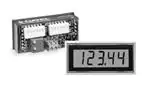
DMS-40LCD-4/20S Series
www.murata-ps.com
Ultra-Low 2.9V Loop-Drop 4½ Digit
LCD Display Process Monitor
The DMS-40LCD-4/20S’s ultra-low 2.9V typical loop-drop (190-Ohm burden) makes it
ideal for use in 4-20mA process monitoring applications which have two or more seriesconnected loop-monitoring devices. The low loop-burden means it can be used in current
loops that are powered from supply voltages as low as +8Vdc! The DMS-40LCD-4/20S is
self-powered; all required operating power is derived directly from the current loop itself.
It requires no separate dc power supply or special grounding considerations and can be
connected ANYWHERE in the loop!
FEATURES
Loop-powered, no power supply required!
2.9V typical loop-drop; 190-Ohm (max.) loop
impedance
Dip-switch-selectable range, offset, and
decimal points
Hundreds of different input/readout combinations
The DMS-40LCD-4/20S’s input, span, and offset circuits all employ super-stable, ±0.5%
thin-film chip resistors. Long-term stability and accuracy are assured by driving these tighttolerance resistors with an ultra-stable, ±0.2% band-gap voltage reference. Unlike many
competitor’s designs, the two precision 20-turn span and zero adjust poten- tiometers
do not interact with one another. Its full-size, 0.40” (10.0mm) high-contrast 4½ digit LCD
display offers 19,999 counts of resolution and can be read in virtually any lighting condition—including full sunlight!
Non-interacting gain (span) and offset (zero)
20-turn potentiometers
Large, 0.40” (10.0mm) high, sunlight-viewable
LCD digits
Miniature size: 2.17" x 0.92" x 0.90"
(55mm x 23mm x 23mm)
All range-change and decimal point selections are made by configuring two gold-plated, vibration-resistant, six-position DIP switches. The two connections to the current loop
are made via a reliable, screw-type terminal block. To further enhance reliability, the design
features 100% soldered connections—no troublesome zebra/elastomercic connectors are
used. All these outstanding features make the DMS-40LCD-4/20S the highest quality, most
rugged, 4½ digit, LCD-display process monitor available.
Vibration-resistant package; reliable screwterminal connections
100% soldered connections
4½ DIGIT A/D
CONVERTER
Range
Offset
Gain
DATA
R3
DP1
R7
ZERO
ADJUST
DP2
DP3
DP4
GAIN
ADJUST
BAND-GAP
REFERENCE
CIRCUIT
ON
ON
S1
S2
1
+5V
2
3
4
5
6
1
2
3
4
6
5
–5V
TB1
DC/DC
CONVERTER
CURRENT TO
VOLTAGE
CONVERTER
For full details go to
www.murata-ps.com/rohs
Figure 1. DMS-40LCD-4/20S Simplified Schematic
+
–
1
2
+
–
4-20mA
Current Loop Input
www.murata-ps.com/support
MPM_DMS-40LCD-420.C01 Page 1 of 5
�DMS-40LCD-4/20S Series
Ultra-Low 2.9V Loop-Drop 4½ Digit
LCD Display Process Monitor
Performance/Functional Specifications
Typical at TA = +25°C, unless otherwise noted.
Current Loop Input
Min.
Typ.
Max.
Units
Full Scale Input Range (1)
+3.8
–
+20.4
mA
Loop Burden(2)
–
–
190
Ohms
Voltage Drop (2)
–
2.9
3.8
Volts
Overcurrent Protection
–
–
±40
mA
Performance
Sampling Rate
2.5 reading per second
Accuracy (1 minute warm-up)
±0.05%FS ±1 Count
Temperature Drift of Span(3)
–
±0.3
±0.6
Cnts/°C
Temperature Drift of Zero(3)
–
±0.2
±0.5
Cnts/°C
Display
DisplayType and Size
4½digit, 0.4”/10.2mmhigh LCD
Polarity Indication
“–” for negative readings
“–1___” for negative inputs
“1___” for positive inputs
Overrange Indication
Physical/Environmental
OperatingTemperature
StorageTemperature
Humidity (non-condensing)
0
–
+50
°C
–20
–
+75
°C
0
–
95
°C
Case Material
Polycarbonate
Weight
0.1 ounces (28 grams)
Ordering Information
DMS-40LCD-4/20S-C
DMS-BZL1-C
DMS-BZL2-C
DMS-30-CP
4½ digit, LCD, loop-powered meter
Panel-mount bezel assembly
Panel-mount bezel assembly with
sealing gasket
Panel cutout punch
A panel-mount retaining clip is supplied with each meter.
TECHNICAL NOTES
(1) Full Scale Input: The Display readings shown in Table 1 can typically be obtained with transmitters having a low-level output of 3.8
to 4.3mA and a full-scale output of 19.4 to 20.4mA. When using a
transmitter whose output falls outside these ranges and the desired
display read- ings are close to the upper or lower adjustment limits
of the selected DIP-switch setting #, try using the next highest DIPswitch setting # if, after adjusting R7, the display reading is still too
low, or the next lowest setting # if the display reading is still too high
(see example number 2). Please keep in mind that the DMS-40LCD
meter from which the DMS-40LCD-4/20S is derived has an accuracy
specification of ±3 counts (max.); thus, it may not always be possible
to obtain the exact desired display readings. Achange of ±1 count is
defined as the right-hand most digit going up or down by one.
Consult Murata Power Solutions for more information regarding
display readings not shown in the table.
(2) Max. Loop-Voltage Drop/Max. Loop impedance: The maximum
loop voltage-drop and maximumloop impedance (burden) are both
speci- fied with the meter configured for DIP-Switch setting #20 and
an input loop current of 20.0mA.
(3) Temperature Drift: Temperature drift of zero and temperature drift of
gain are both specified with the meter configured for range #20 with
a 4mAinput adjusted (using R3) to read “0000” ±1 count, and a 20mA
input adjusted (using R7) to read “19000” ±2 counts at an initial
ambi- ent temperature of 25°C.
The temperature drift of gain is proportional to the selected full-scale
range. It is typically less pronounced at the lower range settings, that
is, if the observed gain drift of a particular meter is +12 counts when
reading “19000” on range #20 at 40°C, the same meter will most
likely have a drift of only +6 counts when reading “9000” on range
#12 at 40°C.
The normally very accurate, temperature-insensitive autozero feature
of the DMS-40LCD-4/20S’s built-in analog-to-digital converter (A/D)
is not a significant factor in determining the meter’s overall zeroreading stability over its rated operating temperature because an
offset voltage is applied to the A/D’s LOinput. This offset is used to
null the signal voltage developed with a 4mAinput. In order for the A/
Dto display a steady “0000” ±1 digit, the autozero circuitry requires
both A/Dinputs to always be at exactly zero volts.
The meter’s zero-reading stability over its specified operating temperature is affected by the drift of three terms: the voltage developed by
the meter’s offset circuitry; the voltage developed across the meter’s
input resistors with a 4mAinput; and the stability of the applied
4mAinput signal itself. In the lower DIP-switch settings (ranges #1-4),
the meter’s parasitic etch and switchimpedances also contribute a
small error voltage.
The meter’s performance with regards to span stability over temperature is affected by the drift of the meter’s gain circuitry and loop
input-resistors. To minimize these drifts in applications requiring the
utmost in temperature stability, where possible, the meter should be
calibrated at its anticipated operating temperature.
Since the DMS-40LCD-4/20S uses extremely-stable thin-filmchip
resistors, periodic re-calibration is typically required only in environmentally demanding applications where shock, vibration, and/or
temperature extremes may have a detrimental effect on the 20-turn
potentiometers.
DECIMAL POINT SETTINGS
Using the chart below as a guide, the DMS-40LCD-4/20S’s decimal
points can be configured to suit the user’s particular readout requirements. To enable a desired decimal point place its DIPswitch to the
ON position (up). Please note that the decimal points are merely
placeholders, that is, they can all be on or all off; they do not affect
the meter’s operation and/or display readings.
Display readings other than those shown in Table 1 are obtainable.
For example, some negative readings with a 4mA input are possible.
www.murata-ps.com/support
MPM_DMS-40LCD-420.C01 Page 2 of 5
�DMS-40LCD-4/20S Series
Ultra-Low 2.9V Loop-Drop 4½ Digit
LCD Display Process Monitor
3. Desired display readings are:
Switch S2
S1
4mA = “0000”
SW3
SW4
SW5
SW6
DP1
DP2
DP3
DP4
S2
ON
20mA = “10000”
1
2
ON
4
3
6
5
2
1
4
3
Use DIP-switch setting #13. Apply 4mA and adjust R3 so the display
reads “0000.” Apply 20mA and adjust R7 so the display reads “10000.”
For these display readings no decimal points are used. Set SW3, SW4,
OPERATING AND SETUP INSTRUCTIONS
The following procedure must be performed as the first re-calibration
step every time DIP-switches S1 and S2 are reconfigured to select a
new display range. The following procedure assumes the DMS-40LCD4/20S is initially completely mis-adjusted, i.e., both potentiometers and
DIP-switches S1 and S2 are randomly set. Make sure that all DIP-switch
actuators are pushed as far as they will go to their designated ON
(closed) or OFF (open) positions.
1. Set R7 (gain/span adjust) and R3 (zero/offset adjust) fully clockwise,
roughly 20 turns, then using the settings found in the selected range,
place the DIP-switches on S1 and S2 to the appropriate positions for
the desired display reading.
2. Apply a precision 4mA input with proper polarity and adjust R3 (top
20-turn potentiometer) until the meter’s display reads “0000.”
3. Apply a precision 20mA input and adjust R7 (bottom 20-turn
potentiometer) until the display reads the maximum desired reading.
Repeat steps 2 and 3 to make sure the adjustments did not affect
one another.
SW5 and SW6 of switch S2 to OFF.
S1
4. Desired display readings are:
4mA = “.0000”
S2
ON
12mA = “.2500”
1
2
3
ON
4
5
1
6
2
3
4
This example is not as straightforward as the previous three. Notice that
12mA is exactly halfway between 4mA and 20mA. If we assume the
input could go up to 20mA, the display reading would then be 2 x .2500
or “.5000.” From Table 1, select DIP-switch setting #7 and enable DP1
via SW3 of switch S2. Apply 4mA and adjust R3 so the display reads
“.0000.” Apply 12mA and adjust R7 so the display reads “.2500.”
Table 1. DIP-Switch Settings
Switch S1
Display Reading
4mA
Switch S2
SW1 SW2 SW3 SW4 SW5 SW6 SW1 SW2
20mA
01. 0000 2250-2450
OFF
ON
ON
ON
OFF
OFF
ON
ON
4. If necessary, select the appropriate decimal point by setting either
SW3, SW4, SW5, or SW6 of S2 to ON (DP1, DP2, DP3, or DP4, respectively.
02. 0000 2450-2800
OFF
ON
ON
ON
OFF
OFF OFF
ON
03. 0000 2800-3200
OFF
ON
ON
ON
OFF
OFF
OFF
04. 0000 3200-3850
OFF
ON
ON
ON
OFF
OFF OFF OFF
NOTE: Please keep in mind the transmitter’s 4mA and 20mA output
accuracy may affect display readings which are at, or very close to, the
high and low limits of the selected range. See Example #2 below and
Technical Note 1 for more information).
05. 0000 3850-4250
ON
OFF
ON
ON
OFF
OFF
06. 0000 4250-4800
ON
OFF
ON
ON
OFF
OFF OFF
ON
07. 0000 4800-5500
ON
OFF
ON
ON
OFF
OFF
OFF
08. 0000 5500-6200
ON
OFF
ON
ON
OFF
OFF OFF OFF
09. 0000 6200-6750
OFF
OFF
ON
ON
ON
OFF
10. 0000 6750-7700
OFF
OFF
ON
ON
ON
OFF OFF
ON
11. 0000 7700-8600
ON
ON
OFF
ON
ON
OFF
ON
ON
12. 0000 8600-9800
ON
ON
OFF
ON
ON
OFF OFF
ON
13. 0000 9800-10900
ON
ON
ON
OFF
OFF
ON
ON
ON
14. 0000 10900-12000
ON
ON
ON
OFF
OFF
ON
OFF
ON
15. 0000 12000-12800
ON
OFF
OFF
ON
OFF
ON
ON
ON
16. 0000 12800-14000
ON
OFF
OFF
ON
OFF
ON
OFF
ON
17. 0000 14000-15300
ON
OFF
ON
OFF
ON
ON
ON
ON
18. 0000 15300-16300
ON
OFF
ON
OFF
ON
ON
OFF
ON
19. 0000 16300-17600
OFF
OFF
ON
OFF
ON
ON
ON
ON
20. 0000 17600-19999
OFF
OFF
ON
OFF
ON
ON
OFF
ON
Examples
The examples below illustrate how to configure the meter to perform
some typical measurements. Recall that R3 and R7 must be set to their
full clockwise position before calibrating the meter.
1. Desired display readings are:
S1
ON
4mA = “0.000”
20mA = “3.000”
S2
1
2
1
6
5
2
4
3
Use DIP-switch setting #3 in Table 1 and enable decimal point DP2 by
placing SW4 of switch S2 to ON. Apply 4mA and adjust R3 so the display
reads “0.000.” Apply 20mA and adjust R7 so the display reads “3.000.”
2. Desired display readings are:
S1
S2
ON
ON
4mA = “0000”
20mA = “8600”
1
2
3
ON
ON
ON
ON
ON
ON
4
3
ON
4
5
6
1
2
3
4
Use DIP-switch setting #11. Apply 4mA and adjust R3 so the display
reads “0000.” Apply 20mA and adjust R7 so the display reads “8600.” If
the transmitter’s full-scale output is less than 20.0mA, it may not be possible to adjust R7 for a reading of “8600” with setting #11. If this occurs,
select setting #12 and re-calibrate both R3 and R7 to obtain “0000” and
“8600.” Note that for these display readings no decimal points are used.
Set SW3, SW4, SW5 and SW6 of switch S2 to OFF.
www.murata-ps.com/support
MPM_DMS-40LCD-420.C01 Page 3 of 5
�DMS-40LCD-4/20S Series
Ultra-Low 2.9V Loop-Drop 4½ Digit
LCD Display Process Monitor
APPLICATIONS
PROGRAMMABLE
LOGIC CONTROLLER
–
+
DMS-40LCD-4/20S
TRANSMITTER &
SIGNAL CONDITIONER
4-20mA
GAIN
+
R7
(TB1-1)
TRANSDUCER
INPUT
+
+
Vsig
A/D
R3
–
(TB1-2)
–
ZERO
4-20mA
+
+24V
+24Vdc
SUPPLY
–
Figure 2. Typical DMS-40LCD-4/20S Connections
www.murata-ps.com/support
MPM_DMS-40LCD-420.C01 Page 4 of 5
�DMS-40LCD-4/20S Series
Ultra-Low 2.9V Loop-Drop 4½ Digit
LCD Display Process Monitor
MECHANICAL SPECIFICATIONS
MECHANICAL DIMENSIONS: Inches (mm)
2 PL DEC ±0.02 (±0.51)
3 PL DEC ±0.010 (±0.254)
18 to 26 AWG (Solid or stranded)
0.20" (5.08mm)
TOLERANCES:
WIRE SIZE:
STRIPPING LENGTH:
0.90
(22.9)
0.040
(1.02)
MADE IN USA
DMS-40LCD-4/20S
2.09
(53.1)
0.040
(1.02)
0.040
(1.02)
2.17
(55.1)
1
2
3
4
5
R3
Zero
R7
Span
7
6
PS1
SW2
ON
ON
1
2
3
4
5
6
TB1
+
–
1
2
+
–
LOOP INPUT
#2-56 INSERT
0.156 (3.96) DEEP
FRONT VIEW
0.92
(23.4)
FRONT VIEW
BACK VIEW
SW1
0.84
(21.3)
DP1
S2
(SW3)
DP2
S2
(SW4)
DP3
S2
(SW5)
DP4
S2
(SW6)
0.187
(4.75)
PANEL
MADE IN USA
1.270
(32.26)
OPTIONAL GASKET
2.55 (64.77)
BEZEL
RECOMMENDED DRILL AND PANEL CUTOUT DIMENSIONS
INTERNAL CORNER RADII:
0.032 (0.81) MAX.
1.07
(27.18)
PANEL CUTOUT
0.116
(2.95)
0.878
(22.30)
PANEL
2.118 (53.80)
MADE IN USA
2.35 (59.69)
0.093 (2.362) DIAMETER (4 REQUIRED)
ONLY WHEN USING OPTIONAL BEZEL ASSEMBLY
Murata Power Solutions, Inc.
11 Cabot Boulevard, Mansfield, MA 02048-1151 U.S.A.
ISO 9001 and 14001 REGISTERED
0.096
(2.44)
A panel-mount retaining clip is supplied with all models.
This product is subject to the following operating requirements
and the Life and Safety Critical Application Sales Policy:
Refer to: http://www.murata-ps.com/requirements/
Murata Power Solutions, Inc. makes no representation that the use of its products in the circuits described herein, or the use of other
technical information contained herein, will not infringe upon existing or future patent rights. The descriptions contained herein do not imply
the granting of licenses to make, use, or sell equipment constructed in accordance therewith. Specifications are subject to change without
notice.
© 2015 Murata Power Solutions, Inc.
www.murata-ps.com/support
MPM_DMS-40LCD-420.C01 Page 5 of 5
�