LSN2-T/30-D12 Series
www.murata-ps.com
DOSA-SIP, 30A POL DC/DC Converters
DESCRIPTION
These miniature point-of-load (POL) switching
DC/DCs are an ideal regulation and supply element for mixed voltage systems. The converter
is fully compatible with the Distributed-power
Open Standards Alliance specification
(www.dosapower.com). LSN2-T/30-D12 can
power CPU’s, programmable logic and mixed
voltage systems with little heat and low noise.
A typical application uses a master isolated
12V DC supply and the LSN2-T/30-D12 converter for local 1.8V and 3.3V DC supplies.
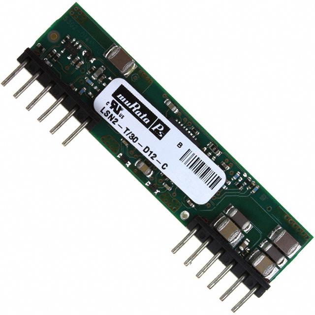
Typical unit
FEATURES
■
Standard (DOSA compatible) SIP package
■
User-selectable outputs: 0.8 to 5Vdc
■
30 Amps maximum output current
■
Meets RoHS-6 standards
■
Selectable phased start-up sequencing,
tracking and pre-bias operation
■
Wide range input voltages 6 to 14Vdc
■
To 150W with overtemperature shutdown
■
Very high efficiency up to 94%
■
Fast settling, high di/dt IOUT slew rate
■
Meets UL 60950-1, CAN/CSA-C22.2 609501, IEC 60950-1, EN60950-1 safety approvals,
2nd edition
■
All system isolation resides in the central
supply, leaving lower cost POL regulation
right at the load. Unlike linear regulators, the
LSN2-T/30-D12 can deliver very high power
(up to 150W) in a tiny area with no heat sinking and no external components needed. The
converter features quick transient response
(to 25μsec) and very fast current slew rates
(to 20A/μsec).
LSN2-T/30-D12 is an open-frame SIP
using advanced surface mount (SMT)
assembly and test techniques. The extraordinary performance is achieved with a fully
synchronous fixed-frequency buck topology
delivering high efficiency, tight line/load
regulation, stable no-load operation and no
output reverse conduction.
Output voltage, selected with an
external programming resistor or DC voltage into the trim pin, means OEM’s can
stock one model for multiple applications.
Also included are protection for out-oflimit voltages, currents and temperature.
Other functions: a remote On/Off control,
optional Power Good output, a phased
start-up sequence and tracking system,
and a load Sense input.
Contents
Extensive self-protection with short circuit
“hiccup” shutdown
Page
Description, Photograph, Connection Diagram
1
Ordering Guide, Model Numbering, Soldering Guidelines
2
■
Output overvoltage/overcurrent protection
Mechanical Specs, Input/Output Pinout
3
■
Input under and overvoltage shutdown
Detailed Electrical Specifications
4
Technical Notes
5
Performance Data
13
+OUTPUT
+INPUT
10.57
+SENSE
➀
COMMON
COMMON
VCC
ON/OFF
CONTROL
PWM
CONTROLLER
CURRENT
SENSE
POWER
GOOD
OUTPUT
REFERENCE &
ERROR AMP
VTRACK/SEQUENCE
INPUT
Typical topology is shown.
Figure 1. LSN2 -T/30-D12 Series Simplified Schematic
➀ Only one phase of two is shown.
VOUT
TRIM
For full details go to
www.murata-ps.com/rohs
www.murata-ps.com/support
MDC_LSN2-T/30-D12 Series.C01Δ Page 1 of 16
�LSN2-T/30-D12 Series
DOSA-SIP, 30A POL DC/DC Converters
PERFORMANCE SPECIFICATIONS AND ORDERING GUIDE ➀
Output
Model ➆
VOUT
(Volts)
IOUT
(Amps)
Power
(Watts)
LSN2-T/30-D12-C
0.8-5
30
150
Input
R/N (mVp-p) ➁
Regulation (max.) ➂
Typ.
Max.
Line
Load
VIN Nom.
(Volts)
25
50
±0.1%
±0.1%
12
➀ Typical at TA = +25°C under nominal line voltage and full-load conditions, unless noted. All
models are tested and specified with external 22µF tantalum input and output 0.01//0.1//10µF
capacitors. These capacitors are necessary to accommodate our test equipment and may not
be required to achieve specified performance in your applications. See I/O Filtering and
Noise Reduction.
➁ Ripple/Noise (R/N) is tested/specified over a 20MHz bandwidth for VOUT > 3.63V and may be
reduced with external filtering. See I/O Filtering and Noise Reduction for details.
Range➅
(Volts)
IIN ➃
(mA/A)
Min.
Typ.
Package
(Case/
Pinout)
6-14
200/11.1
93%
94%
B13, P71
Efficiency ➄
➂ These devices have no minimum-load requirements and will regulate under no-load conditions.
Regulation specifications describe the output-voltage deviation as the line voltage or load is
varied from its nominal/midpoint value to either extreme.
➃ Nominal line voltage, no-load/full-load conditions.
➄ LSN2-T/30-D12 efficiencies are shown at 5VOUT.
➅ Input range is 6-14V if VOUT ≤3.63V. For VOUT > 3.63V, the input range is 7–14V.
➆ Please refer to the Part Number Structure for additional options when ordering.
PART NUMBER STRUCTURE
L SN2 - T / 30 - D12 G - C
RoHS-6 hazardous substance compliant
(does not claim EU RoHS exemption 7b–lead in solder)
Output Configuration:
L = Unipolar
Low Voltage
Power Good:
Blank = Omitted (default)
G = Installed (special quantity orders required)
Non-Isolated Through-hole
Nominal Output Voltage:
0.8-5 Volts
Maximum Rated Output
Current in Amps
Input Voltage Range:
D12 = 7-14 Volts (12V nominal)
Note:
Some model number combinations may not be available. Contact
Murata Power Solutions.
SOLDERING GUIDELINES
Murata Power Solutions recommends the specifications below when installing these converters. These specifications vary depending on the solder type.
Exceeding these specifications may cause damage to the product. Your production environment may differ therefore please thoroughly review these guidelines
with your process engineers.
Wave Solder Operations for through-hole mounted products (THMT)
For Sn/Ag/Cu based solders:
Maximum Preheat Temperature
Maximum Pot Temperature
Maximum Solder Dwell Time
115ºC.
270ºC.
7 seconds
For Sn/Pb based solders:
Maximum Preheat Temperature
Maximum Pot Temperature
Maximum Solder Dwell Time
105ºC.
250ºC.
6 seconds
www.murata-ps.com/support
MDC_LSN2-T/30-D12 Series.C01Δ Page 2 of 16
�LSN2-T/30-D12 Series
DOSA-SIP, 30A POL DC/DC Converters
MECHANICAL SPECIFICATIONS
Case B13
51.3
2.02
48.26
1.900
12.70
0.500
12.19
0.480
2.54
0.100
TYP
1.5
0.06
35.56
1.400
12.70
0.500
2.54
0.100 *
1.02
.040
(x12 or 13*)
9.65
0.380
13 12 11 10
9
11.4
0.45
MAX
8
A*
6
5
4
3
2
1
RECOMMENDED FOOTPRINT -TOP VIEW
1.5
0.06
REF
4.3
0.17
1.5
0.06
TYP
0.76
.030
TYP
SIDE VIEW
50.8
2.00
THIRD ANGLE PROJECTION
12.7
0.50
DIMENSIONS ARE IN INCHES, [mm]
13
12 11 10 9
8
A
6
5
*Pin A
2.54
0.100
TYP
4
3
2
1
TOLERANCES:
2 PLACE ±.02
3 PLACE ±.010
12.70
0.500
MATERIAL:
PINS: COPPER ALLOY
35.56
1.400
Pin
±1°
COMPONENTS SHOWN ARE FOR REFERENCE ONLY
2.54
0.100 *
12.70
0.500
ANGLES:
1.27
0.050
FINISH: (ALL PINS)
TIN OVER NICKEL
INPUT/OUTPUT CONNECTIONS
Function P71
Pin
Function P71
1
+Output
7
No Pin
2
+Output
8
Common
3
+Sense In
9
+Input
4
+Output
10
+Input
VTRACK/Sequence
5
Common
11
6
Common
12
Trim
A
Power Good Out*
13
On/Off Control
*Power Good output is optional. If not installed, the pin is omitted.
Note: Because of the high currents, wire appropriate input, output, and common pins in parallel groups.
www.murata-ps.com/support
MDC_LSN2-T/30-D12 Series.C01Δ Page 3 of 16
�LSN2-T/30-D12 Series
DOSA-SIP, 30A POL DC/DC Converters
Performance/Functional Specifications (1)
Input
Input Voltage Range
See Ordering Guide
Isolation
Not isolated. Input and output
Commons are internally connected.
Start-Up Voltage
5.5 Volts
Undervoltage Shutdown
5.2 Volts
Overvoltage Shutdown
None
Reflected (Back) Ripple Current (2)
20mAp-p
Internal Input Filter Type
Capacitive
Reverse Polarity Protection
None. Install external fuse.
Input Current:
Full Load Conditions
Inrush Transient
Shutdown Mode (Off, UV, OT)
Output Short Circuit
No Load, 5VOUT
Low Line (VIN = VMIN, 5VOUT)
Remote On/Off Control: (5)
Negative Logic (No suffix)
Current
Power Good Output (15)
Configuration
Positive-true open drain FET with internal
10 Kilohm pullup to +5 Vdc
TRUE (power is okay) = High, approx. 5Vdc
FALSE (power is not ready) = Low, < 1V typ.,
while DC/DC is powered
4.5 mA max. (< 1mA is recommended
to retain Vpg < 1V)
Soft start is active, Tracking is active, output
is greater than ±10% out of regulation,
overcurrent, or overtemperature
Operation
External sink current
FALSE conditions (OR’d)
See Ordering Guide
0.4A2sec
5mA
60mA
200mA
18.8 Amps
ON = 0 to +0.3V max.
OFF = +2.5V min. to +Vin max.
1 mA max.
Output
Dynamic Characteristics
Dynamic Load Response
(50-100-50% step, di/dt = 20A/msec)
60µsec to within ±2% of final value
Start-Up Time
7mS for VOUT = nominal
(VIN on to VOUT regulated or On/Off to VOUT)
Switching Frequency
520 ±50kHz
Environmental
Calculated MTBF (4)
4, 018, 248 Hours
Operating Temperature Range
–40 to +85°C with derating
See Derating Curves
Operating PC Board Temperature
–40 to +100°C max. (12)
Storage Temperature Range
–55 to +125°C
Voltage Output Range
See Ordering Guide
Thermal Protection/Shutdown
+115°C
Minimum Loading
No minimum load
Relative Humidity
To 85°C/85% RH, non-condensing
Accuracy (50% load)
±1.5% of Vnominal
Voltage Adjustment Range (13)
See Ordering Guide
Overvoltage Protection
None
Temperature Coefficient
±0.02% per °C of VOUT range
Ripple/Noise (20 MHz bandwidth)
See Ordering Guide (8)
Line/Load Regulation (See Tech. Notes) See Ordering Guide (10)
Efficiency
See Ordering Guide
Maximum Capacitive Loading (15)
Cap-ESR = 0.001 to 0.01Ω
Cap-ESR > 0.01Ω
5,000µF
10,000μF
Current Limit Inception
(98% of VOUT setting)
48 Amps (cold startup)
42 Amps (after warm up)
Short Circuit Mode (6)
Short Circuit Current Output
Protection Method (14)
Short Circuit Duration
Pre-bias Startup (16)
Sequencing
Slew Rate
Startup delay until sequence start
Tracking accuracy, rising input
Tracking accuracy, falling input
Remote Sense to VOUT
Physical
Outline Dimensions
See Mechanical Specifications
Weight
0.28 ounces (7.8 grams)
Electromagnetic Interference
Meets class B, EN55022/CISPR22 (conducted
and radiated) (may need external filter)
Safety
Meets UL/cUL 60950-1, CSA-C22.2
No. 60950-1, IEC/EN 60950-1, 2nd edition
600mA
Hiccup autorecovery on overload removal
Continuous, no damage
(output shorted to ground)
Converter will start up if the external
output voltage is less than VNOMINAL
2V max. per millisecond
10 milliseconds
Vout= ±200mV of Sequence In
VOUT = ±400mV of Sequence In
0.5V max.
(7)
ABSOLUTE MAXIMUM RATINGS
Input Voltage (Continuous or transient)
+15 Volts
On/Off Control
0V min. to + VIN max.
Input Reverse Polarity Protection
None. Install external fuse.
Output Current (7)
Current-limited. Devices can withstand
sustained short circuit without damage.
Storage Temperature
–55 to +125°C
Lead Temperature
See soldering guidelines
These are stress ratings. Exposure of devices to greater than any of these conditions may
adversely affect long-term reliability. Proper operation under conditions other than those listed in
the Performance/Functional Specifications Table is not implied.
www.murata-ps.com/support
MDC_LSN2-T/30-D12 Series.C01Δ Page 4 of 16
�LSN2-T/30-D12 Series
DOSA-SIP, 30A POL DC/DC Converters
Performance/Functional Specification Notes:
(1) Specifications are typical at +25°C, VIN = nominal (+12V), VOUT = nominal (+5V), full
load, external caps and natural convection unless otherwise indicated.
All models are tested and specified with external 0.01µF, 0.1µF, and 10µF (all paralleled) ceramic/tantalum output capacitors and a 22µF external input capacitor. All
capacitors are low ESR types. These capacitors are necessary to accommodate our
test equipment and may not be required to achieve specified performance in your
applications. All models are stable and regulate within spec under no-load conditions.
(2) Input Back Ripple Current is tested and specified over a 5Hz to 20MHz bandwidth.
Input filtering is CIN = 2 x 100µF tantalum, CBUS = 1000µF electrolytic, LBUS = 1µH.
(3) Note that Maximum Power Derating curves indicate an average current at nominal
input voltage. At higher temperatures and/or lower airflow, the DC/DC converter will
tolerate brief full current outputs if the total RMS current over time does not exceed the
Derating curve.
(8) Output noise may be further reduced by adding an external filter. See I/O Filtering and
Noise Reduction.
(9) All models are fully operational and meet published specifications, including “cold start”
at –40°C.
(10) Regulation specifications describe the deviation as the line input voltage or output load
current is varied from a nominal midpoint value to either extreme.
(11) Other input or output voltage ranges will be reviewed under scheduled quantity special
order.
(12) Maximum PC board temperature is measured with the sensor in the center.
(13) Do not exceed maximum power specifications when adjusting the output trim.
(14) After short circuit shutdown, if the load is partially removed such that the load still
exceeds the overcurrent (OC) detection, the converter will remain in hiccup restart mode.
(4) Mean Time Before Failure is calculated using the Telcordia (Belcore) SR-332
Method 1, Case 3, ground fixed conditions, TPCBOARD = +25°C, full output load,
natural air convection.
(15) Static Discharge CAUTION: The Power Good output connects directly to the PWM
controller. Be sure to use proper grounding techniques to avoid damaging the converter.
Power Good is not valid when using Sequence/Tracking.
(5) The On/Off Control may be driven with external logic or by applying appropriate external voltages which are referenced to –Input Common. The On/Off Control Input should
use either an open collector/open drain transistor or logic gate.
(16) The maximum output capacitive loads depend on the the Equivalent Series Resistance
(ESR) of theexternal output capacitor. Larger caps will reduce output noise but may
slow transient response or degrade dynamic performance. Use only as much output filtering as needed and no more. Thoroughly test your system under full load, especially
with low-ESR ceramic capacitors.
(6) Short circuit shutdown begins when the output voltage degrades approximately 2%
from the selected setting.
(7) If Sense is connected remotely at the load, up to 0.5 Volts difference is allowed between
the Sense and +VOUT pins to compensate for ohmic voltage drop in the power lines.
A larger voltage drop may cause the converter to exceed maximum power dissipation.
Connect sense to +VOUT at the converter if sense is not connected to a remote load.
(17) Do not use Pre-bias startup and sequencing together. See the Technical Notes below.
TECHNICAL NOTES
I/O Filtering and Noise Reduction
All models in the LSN2-T/30-D12 Series are tested and specified with external
0.01µF, 0.1µF, and 10µF (all paralleled) ceramic/tantalum output capacitors and a 22μF tantalum input capacitor. These capacitors are necessary to
accommodate our test equipment and may not be required to achieve desired
performance in your application. The LSN2-T/30-D12’s are designed with
high-quality, high-performance internal I/O caps, and will operate within spec
in most applications with no additional external components.
In particular, the LSN2-T/30-D12’s input capacitors are specified for low
ESR and are fully rated to handle the units’ input ripple currents. Similarly, the
internal output capacitors are specified for low ESR and full-range frequency
response.
4/
/3#),,/3#/0%
�
�).054
,"53
�
6).
#522%.4
02/"%
#"53
#).
n
�
#/--/.
#).��X���§&�%32����M7 ���K(Z
#"53�����§&�%32����M7 ���K(Z
,"53��§(
Figure 2. Measuring Input Ripple Current
In critical applications, input/output ripple/noise may be further reduced using
filtering techniques, the simplest being the installation of external I/O caps.
External input capacitors serve primarily as energy-storage devices. They
minimize high-frequency variations in input voltage (usually caused by IR drops
in conductors leading to the DC/DC) as the switching converter draws pulses of
current. Input capacitors should be selected for bulk capacitance (at appropriate frequencies), low ESR, and high rms-ripple-current ratings. The switching
nature of modern DC/DCs requires that the dc input voltage source have low ac
impedance at the frequencies of interest. Highly inductive source impedances
can greatly affect system stability. Your specific system configuration may
necessitate additional considerations.
Output ripple/noise (also referred to as periodic and random deviations or
PARD) may be reduced below specified limits with the installation of additional
external output capacitors. Output capacitors function as true filter elements
and should be selected for bulk capacitance, low ESR, and appropriate frequency response. Any scope measurements of PARD should be made directly
at the DC/DC output pins with scope probe ground less than 0.5" in length.
All external capacitors should have appropriate voltage ratings and be located
as close to the converters as possible. Temperature variations for all relevant
parameters should be taken into consideration.
www.murata-ps.com/support
MDC_LSN2-T/30-D12 Series.C01Δ Page 5 of 16
�LSN2-T/30-D12 Series
DOSA-SIP, 30A POL DC/DC Converters
�3%.3%
The specification defines the interval between the time at which the converter
is turned on and the fully loaded output voltage enters and remains within its
specified accuracy band. See Typical Performance Curves.
#/00%2342)0
�/54054
#�
#�
3#/0%
2,/!$
#/--/.
#/00%2342)0
#���§&#%2!-)#
#����§&4!.4!,5,/!$�
�).#(%3���
��MM &2/--/$5,%
Figure 3. Measuring Output Ripple/Noise (PARD)
The most effective combination of external I/O capacitors will be a function
of your line voltage and source impedance, as well as your particular load and
layout conditions.
Input Fusing
Most applications and or safety agencies require the installation of fuses at the
inputs of power conversion components. The LSN2-T/30-D12 Series are not
internally fused. Therefore, if input fusing is mandatory, either a normal-blow
or a slow-blow fuse with a value no greater than twice the maximum input current calculated at low line with the converter’s minimum efficiency should be
installed within the ungrounded input path to the converter.
Safety Considerations
LSN2-T/30-D12 SIPs are non-isolated DC/DC converters. In general, all DC/DC’s
must be installed, including considerations for I/O voltages and spacing/separation requirements, in compliance with relevant safety-agency specifications
(usually UL/IEC/EN60950-1).
In particular, for a non-isolated converter’s output voltage to meet SELV
(safety extra low voltage) requirements, its input must be SELV compliant. If the
output needs to be ELV (extra low voltage), the input must be ELV.
Input Overvoltage and Reverse-Polarity Protection
LSN2-T/30-D12 SIP Series DC/DCs do not incorporate either input overvoltage
or input reverse-polarity protection. Input voltages in excess of the specified
absolute maximum ratings and input polarity reversals of longer than “instantaneous” duration can cause permanent damage to these devices.
Start-Up Time
The VIN to VOUT Start-Up Time is the interval between the time at which a ramping input voltage crosses the lower limit of the specified input voltage range
and the fully loaded output voltage enters and remains within its specified
accuracy band. Actual measured times will vary with input source impedance,
external input capacitance, and the slew rate and final value of the input voltage
as it appears to the converter.
Remote Sense
LSN2-T/30-D12 Series offer an output sense function. The sense function
enables point-of-use regulation for overcoming moderate IR drops in conductors and/or cabling. Since these are non-isolated devices whose inputs and
outputs usually share the same ground plane, sense is provided only for the
+Output.
The remote sense line is part of the feedback control loop regulating the
DC/DC converter’s output. The sense line carries very little current and consequently requires a minimal cross-sectional-area conductor. As such, it is not a
low-impedance point and must be treated with care in layout and cabling. Sense
lines should be run adjacent to signals (preferably ground), and in cable and/or
discrete-wiring applications, twisted-pair or similar techniques should be used.
To prevent high frequency voltage differences between VOUT and Sense, we
recommend installation of a 1000pF capacitor close to the converter.
The sense function is capable of compensating for voltage drops between
the +Output and +Sense pins that do not exceed 10% of VOUT.
[VOUT(+) – Common] – [Sense(+) – Common] ≤ 10%VOUT
Power derating (output current limiting) is based upon maximum output current and voltage at the converter’s output pins. Use of trim and sense functions
can cause the output voltage to increase, thereby increasing output power
beyond the LSN2-T/30-D12’s specified rating. Therefore:
(VOUT at pins) x (IOUT) ≤ rated output power
The internal 10.5Ω resistor between +Sense and +Output (see Figure 1)
serves to protect the sense function by limiting the output current flowing
through the sense line if the main output is disconnected. It also prevents
output voltage runaway if the sense connection is disconnected.
Note: If the sense function is not used for remote regulation, +Sense
must be tied to +Output at the DC/DC converter pins.
Remote On/Off Control
Normally this input is controlled by the user’s external transistor or relay or is
permanently grounded. With simple external circuits, it may also be selected
by logic outputs. The On/Off control takes effect only when appropriate input
power has been applied and stabilized (approximately 7msec).
For negative polarity, the default operation leaves this pin grounded or LOW.
The output will then always be on (enabled) whenever appropriate input power
is applied.
Dynamic control of the On/Off must be capable of sinking or sourcing the
control current (approximately 1mA max.) and not overdrive the input greater
than the +VIN power input. Always wait for the input power to stabilize before
activating the On/Off control.
The On/Off to VOUT Start-Up Time assumes the converter is turned off via the
On/Off Control with the nominal input voltage already applied to the converter.
www.murata-ps.com/support
MDC_LSN2-T/30-D12 Series.C01Δ Page 6 of 16
�LSN2-T/30-D12 Series
DOSA-SIP, 30A POL DC/DC Converters
Power-up Sequencing
If a controlled start-up of one or more LSN2-T/30-D12 Series DC/DC converters
is required, or if several output voltages need to be powered-up in a given
sequence, the On/Off control pin can be driven with an external device as per
Figure 4.
Output Overvoltage Protection
LSN2-T/30-D12 SIP Series DC/DC converters do not incorporate output
overvoltage protection. In the extremely rare situation in which the device’s
feedback loop is broken, the output voltage may run to excessively high levels
(VOUT = VIN). If it is absolutely imperative that you protect your load against
any and all possible overvoltage situations, voltage limiting circuitry must be
provided external to the power converter.
+INPUT
4.75KΩ
PWM
Enable
1KΩ
ON/OFF
10KΩ
COMMON
Figure 4. On/Off Control Using An External Driver
(Typical circuit)
Output Overcurrent Detection
Overloading the power converter’s output for an extended time will invariably
cause internal component temperatures to exceed their maximum ratings
and eventually lead to component failure. High-current-carrying components
such as inductors, FET’s and diodes are at the highest risk. LSN2-T/30-D12
SIP Series DC/DC converters incorporate an output overcurrent detection and
shutdown function that serves to protect both the power converter and its load.
Output Reverse Conduction
Many DC/DCs using synchronous rectification suffer from Output Reverse
Conduction. If those devices have a voltage applied across their output before
a voltage is applied to their input (this typically occurs when another power
supply starts before them in a power-sequenced application), they will either
fail to start or self destruct. In both cases, the cause is the “freewheeling” or
“catch” FET biasing itself on and effectively becoming a short circuit.
LSN2-T/30-D12 SIP DC/DC converters do not suffer from Output Reverse
Conduction. They employ proprietary gate drive circuitry that makes them
immune to moderate applied output overvoltages.
Thermal Considerations and Thermal Protection
The typical output-current thermal-derating curves shown below enable
designers to determine how much current they can reliably derive from each
model of the LSN2-T/30-D12 SIPs under known ambient-temperature and airflow conditions. Similarly, the curves indicate how much air flow is required to
reliably deliver a specific output current at known temperatures.
The highest temperatures in LSN2-T/30-D12 SIPs occur at their output
inductor, whose heat is generated primarily by I 2 R losses. The derating curves
were developed using thermocouples to monitor the inductor temperature and
varying the load to keep that temperature below +110°C under the assorted
conditions of air flow and air temperature. Once the temperature exceeds
+115°C (approx.), the thermal protection will disable the converter. Automatic
restart occurs after the temperature has dropped below +110°C.
As you may deduce from the derating curves and observe in the efficiency
curves on the following pages, LSN2-T/30-D12 SIPs maintain virtually constant
efficiency from half to full load, and consequently deliver very impressive
temperature performance even if operating at full load.
Lastly, when LSN2-T/30-D12 SIPs are installed in system boards, they are
obviously subject to numerous factors and tolerances not taken into account
here. If you are attempting to extract the most current out of these units under
demanding temperature conditions, we advise you to monitor the outputinductor temperature to ensure it remains below +110°C at all times.
If the output current exceeds it maximum rating by typically 50% or if the
output voltage drops to less than 98% of it original value, the LSN2-T/30-D12’s
internal overcurrent-detection circuitry immediately turns off the converter,
which then goes into a “hiccup” mode. While hiccupping, the converter will
continuously attempt to restart itself, go into overcurrent, and then shut down.
Once the output short is removed, the converter will automatically restart itself.
www.murata-ps.com/support
MDC_LSN2-T/30-D12 Series.C01Δ Page 7 of 16
�LSN2-T/30-D12 Series
DOSA-SIP, 30A POL DC/DC Converters
Start Up Considerations
When power is first applied to the DC/DC converter, operation is different than
when the converter is running and stabilized. There is some risk of start up
difficulties if you do not observe several application features. Lower output
voltage converters may have more problems here since they tend to have
higher output currents. Operation is most critical with any combination of the
following external factors:
1 – Low initial input line voltage and/or poor regulation of the input source.
2 – Full output load current on lower output voltage converters.
3 – Slow slew rate of input voltage.
4 – Longer distance to input voltage source and/or higher external input
source impedance.
For many systems, the CPU and memory must be powered up, boot-strap
loaded and stabilized before the I/O section is turned on. This avoids uncommanded data bytes being transferred, compromising an already-running
external network or placing the I/O section in an undefined mode. Or it keeps
bad commands out of disk and peripheral controllers until they are ready to go
to work.
Another goal for staggered power-up is to avoid an oversize load applied to
the master source all at once. A more serious reason to manage the timing and
voltage differences is to avoid either a latchup condition in programmable logic
(a latchup might ignore commands or would respond improperly to them) or a
high current startup situation (which may damage on-board circuits). And on
the power down phase, inappropriate timing or voltages can cause interface
logic to send a wrong “epitaph” command (Figure 5).
5 – Limited or insufficient ground plane. External wiring that is too small.
6 – Too small external input capacitance. Too high ESR.
+12Vdc
7 – High output capacitance causing a start up charge overcurrent surge.
8 – Output loads with excessive inductive reactance or constant current
characteristics.
If the input voltage is already at the low limit before power is applied, the
start up surge current may instantaneously reduce the voltage at the input
terminals to below the specified minimum voltage. Even if this voltage depression is very brief, this may interfere with the on-board controller and possibly
cause a failed start. Or the converter may start but the input current load will
now drive the input voltage below its running low limit and the converter will
shut down.
If you measure the input voltage before start up with a Digital Voltmeter (DVM),
the voltage may appear to be adequate. Limited external capacitance and/or
too high a source impedance may cause a short downward spike at power up,
causing an instantaneous voltage drop. Use an oscilloscope not a DVM to observe
this spike. The converter’s soft-start controller is sensitive to input voltage. What
matters here is the actual voltage at the input terminals at all times.
“ALL ON”
+VIN
+5V
LOADS
POL
B
+3.3V
LOADS
ENABLE
SEQUENCING
CONTROLLER
CPU
+VIN
ENABLE
TO OTHER POLs
STARTUP SEQUENCE:
ENABLE
ON
OFF
Symptoms of start-up difficulties may include failed started, output oscillation or brief start up then overcurrent shutdown. Since the input voltage is never
absolutely constant, the converter may start up at some times and not at others.
POL A
LSN2-T/30-D12 Power Sequencing
In older systems, one master switch simultaneously turned on the power for all
parts of an application. Many modern systems require multiple supply voltages
for different on-board sections. Typically the CPU or microcontroller needs
1.8 Volts or lower. Memory (particularly DDR) may use 1.8 to 2.5 Volts. Interface “glue” and “chipset” logic might use +3.3Vdc power while Input/Output
subsystems may need +5V. Finally, peripherals use 5V and/or 12V.
POL B
Timing is Everything
This mix of system voltages is being distributed by several local power solutions including Point-of-load (POL) DC/DC converters and sometimes a linear
regulator, all sourced from a master AC power supply. While this mix of voltages is challenging enough, a further difficulty is the start-up and shutdown
timing relationship between these power sources and relative voltage differences between them.
POL
A
Settling
Delay
ON
OFF
TIME
Figure 5. Power Up/Down Sequencing Controller
Two Approaches
There are two ways to manage these timing and voltage differences. Either the
power up/down sequence can be controlled by discrete On/Off logic controls
for each power supply (see Figure 5). Or the power up/down cycle is set by
Sequencing or Tracking circuits. Some systems combine both methods.
www.murata-ps.com/support
MDC_LSN2-T/30-D12 Series.C01Δ Page 8 of 16
�LSN2-T/30-D12 Series
DOSA-SIP, 30A POL DC/DC Converters
/54054
6/,4!'%
/54054
6/,4!'%
0/,!6/54
0/,!6/54
0/,"6/54
3TAGGERED
4IMES
0/,"6/54
�6/54
$ELAYED
6/544IMES
4)-%
4)-%
Figure 6. Coincident or Simultaneous Phasing (Identical Slew Rates)
The first system (discrete On/Off controls) applies signals from an alreadypowered logic sequencer or dedicated microcontroller which turns on each
downstream power section in cascaded series. This of course assumes all
POLs have On/Off controls. A distinct advantage of the sequencing controller
is that it can produce an “All On” output signal to state that the full system is
stable and ready to go to work. For additional safety, the sequencer can monitor the output voltages of all downstream POLs with an A/D converter system.
Figure 8. Staggered or Sequential Phasing—Inclusive (Fixed Delays)
/54054
6/,4!'%
.OT$RAWN4O3CALE
0/,!6/54
0/,"6/54
/54054
6/,4!'%
$ELAYED
6/544IMES
0/,!6/54
4)-%
Figure 9. Staggered or Sequential Phasing—Exclusive
(Fixed Cascaded Delays)
0/,"6/54
#OINCIDENT
6/544IMES
�6).
4)-%
2�
3%1�42+
Figure 7. Proportional or Ratiometric Phasing (Identical VOUT Time)
Figure 7 shows two POLs with different slew rates in order to reach differing
final voltages at about the same time.
However, the sequencer controller has some obvious difficulties besides
extra cost, wiring and programming complexity. First, power is applied as a
fast-rising all-or-nothing step which may be unacceptable to certain circuits,
especially large output bypass capacitors. These could force POLs into overcurrent shutdown. And some circuits (such as many linear regulators and some
POLs) may not have convenient start-up controls. This requires designing and
fabricating external power controls such as high-current MOSFETs.
0/,!
�6/54��6
0/,"
�6/54����6
#�
n6).
3%1�42+
Figure 10. Wiring for Simultaneous Phasing
www.murata-ps.com/support
MDC_LSN2-T/30-D12 Series.C01Δ Page 9 of 16
�LSN2-T/30-D12 Series
DOSA-SIP, 30A POL DC/DC Converters
�6).
2�
3%1�42+
0/,!
1�
50�$.
�6/54��6
#�
n6).
Figure 11. Self-Ramping Power Up
�6).
2�
-!).
2!-0
2!4%
3%1�42+
0/,!
�6/54��6
#�
2�
3%1�42+
0/,"
�6/54����6
#�
!.4)
./)3%&),4%2�����P&490�
Figure 12. Proportional Phasing
07#/.42/,,%2
�6/54
&%%$"!#+
�-7
�6).
42)-
n
�
Power Phasing Architectures
Observe the simplified timing diagrams in this section. There are many possible power phasing architectures and these are just some examples to help
you analyze your system. Each application will be different. Multiple output
voltages may require more complex timing than that shown here.
These diagrams illustrate the time and slew rate relationship between two
typical power output voltages. Generally the Master will be a primary power
voltage in the system which must be present first or coincident with any
Slave power voltages. The Master output voltage is connected to the Slave’s
Sequence input, either by a voltage divider, divider-plus-capacitor or some
other method.
n6).
�6).
Sequence/Track Input
A different power sequencing solution is employed on the LSN2-T/30-D12 DC/DC
converter. After external input power is applied and the converter stabilizes, a
high impedance Sequence/Track input pin accepts an external analog voltage.
The output power voltage will then track this Sequence/Track input at a one-toone ratio up to the nominal set point voltage for that converter. This Sequencing input may be ramped, delayed, stepped or otherwise phased as needed for
the output power, all fully controlled by the user’s simple external circuits. As a
direct input to the converter’s feedback loop, response to the Sequence/Track
input is very fast (milliseconds).
By properly controlling this Sequence pin, most operations of the discrete
On/Off logic sequencer may be duplicated. The Sequence pin system does not
use the converter’s Enable On/Off control (unless it is a master emergency shut
down system).
n6).
2�
If the power up/down timing needs to be closely controlled, each POL must
be characterized for start-up and down times. These often vary—one POL may
stabilize in 15 milliseconds whereas another takes 50 mS. Another problem is
that the sequencing controller itself must be “already running” and stabilized
before starting up other circuits. If there is a glitch in the system, the power
up/down sequencer could get out of step with possible disastrous results.
Lastly, changing the timing may require reprogramming the logic sequencer or
rewriting software.
3%1�
42+
).
Several standard sequencing architectures are prevalent. They are concerned with three factors:
■
The time relationship between the Master and Slave voltages
■
The voltage difference relationship between the Master and Slave.
■
The voltage slew rate (ramp slope) of each converter’s output.
For most systems, the time relationship is the dominant factor. The voltage
difference relationship is important for systems very concerned about possible
latchup of programmable devices or overdriving ESD diodes. Lower slew rates
avoid overcurrent shutdown during bypass cap charge-up.
Figure 13. Sequence/Track Simplified Equivalent Schematic
www.murata-ps.com/support
MDC_LSN2-T/30-D12 Series.C01Δ Page 10 of 16
�LSN2-T/30-D12 Series
DOSA-SIP, 30A POL DC/DC Converters
In Figure 10, two POLs ramp up at the same rate until they reach their
different respective final set point voltages. During the ramp, their voltages
are nearly identical. This avoids problems with large currents flowing between
logic systems which are not initialized yet. Since both end voltages are different, each converter reaches it’s setpoint voltage at a different time.
Figure 12 shows two POLs with different slew rates in order to reach differing final voltages at about the same time.
Operation
To use the Sequence pin after power start-up stabilizes, apply a rising external
voltage to the Sequence input. As the voltage rises, the output voltage will
track the Sequence input (gain = 1). The output voltage will stop rising when it
reaches the normal set point for the converter. The Sequence input may optionally continue to rise without any effect on the output. Keep the Sequence input
voltage below the converter’s input supply voltage.
Use a similar strategy on power down. The output voltage will stay constant
until the Sequence input falls below the set point.
Any strategy may be used to deliver the power up/down ramps. The circuits
below show simple RC networks but you may also use operational amplifiers,
D/A converters, etc.
Circuits
The circuits shown in Figures 5 through 13 introduce several concepts when
using these Sequencing controls on Point-of-Load (POL) converters. These
circuits are only for reference and are not intended as final designs ready for
your application. Also, numerous connections are omitted for clarity.
Figure 10 shows a basic Master (POL A) and Slave (POL B) connected so that
the POL B ramps up identically to POL A as shown in timing diagram Figure 6.
RC network R1 and C1 charge up at a rate set by the R1-C1 time constant,
giving a roughly linear ramp. As POL A reaches 3.3V out (the setpoint of POL B),
POL B will stop rising. POL A then continues rising until it reaches 5V.
R1 should be selected so that it is significantly smaller than the internal
bias current resistor from the Sequence pin. Start with a value of 20 Kilohms.
In Figure 10, we assume that the critical phase is only on power up therefore
there is no provision for ramped power down.
Figure 11 shows a single POL and the same RC network. However we have
added a small FET at Q1 to function as an up/down control. When VIN power is
first applied to the POL, Q1 is biased on, shorting out the Sequence pin. When
Q1’s gate is biased off, R1 now charges C1 and the POL’s output now ramps up
at the R1-C1 slew rate. Note that Q1’s gate would typically be controlled from
some external digital logic.
If you wish to have a ramped power down (rather than a step down), add a
small resistor in series with Q1’s drain.
Figure 12 shows both a RC ramp on Master POL A and a proportional tracking divider (R2 and R3) on POL B. We have also added an optional very small
noise filter cap at C2. Figure 12’s circuit corresponds roughly to Figure 7’s
timing for power up.
Guidelines for Sequence/Track Applications
[1] Leave the converter’s On/Off Enable control (if installed) in the On setting.
Normally, you should just leave the On/Off pin open.
[2] Allow the converter to stabilize (typically less than 20 mS after +VIN power
on) before raising the Sequence input. Also, if you wish to have a ramped
power down, leave +VIN powered all during the down ramp. Do not simply
shut off power.
[3] If you do not plan to use the Sequence/Track pin, leave it open.
[4] Observe the Output slew rate relative to the Sequence input. A rough
guide is 2 Volts per millisecond maximum slew rate. If you exceed this
slew rate on the Sequence pin, the converter will simply ramp up at
it’s maximum output slew rate (and will not necessarily track the faster
Sequence input). The reason to carefully consider the slew rate limitation
is in case you want two different POL’s to precisely track each other.
[5] Be aware of the input characteristics of the Sequence pin. The high input
impedance affects the time constant of any small external ramp capacitor.
And the bias current will slowly charge up any external caps over time
if they are not grounded. The internal pull up resistor to +VIN is typically
400 Kilohms to 1 Megohm.
Notice in the simplified Sequence/Track equivalent circuit (Figure 13) that
a blocking diode effectively disconnects this circuit when the Sequence/
Track pin is left open.
[6] Allow the converter to eventually achieve its full rated setpoint output voltage. Do not remain in ramp up/down mode indefinitely. The converter is
characterized and meets all its specifications only at the setpoint voltage
(plus or minus any trim voltage). During the ramp-up phase, the converter
is not considered fully in regulation. This may affect performance with
excessive high current loads at turn-on.
[7] The Sequence is a sensitive input into the feedback control loop of the
converter. Avoid noise and long leads on this input. Keep all wiring very
short. Use shielding if necessary.
[8] If one converter is slaving to another master converter, there will be a very
short phase lag between the two converters. This can usually be ignored.
[9] You may connect two or more Sequence inputs in parallel from two converters. Be aware of the increasing pull-up bias current and reduced input
impedance.
www.murata-ps.com/support
MDC_LSN2-T/30-D12 Series.C01Δ Page 11 of 16
�LSN2-T/30-D12 Series
DOSA-SIP, 30A POL DC/DC Converters
[10] Any external capacitance added to the converter’s output may affect ramp
up/down times and ramp tracking accuracy.
current. If the resistive load starts successfully, you may be trying to drive an
external pre-biased active source.
Pre-Biased Startup
Newer systems with multiple power voltages have an additional problem
besides startup sequencing. Some sections have power already partially
applied (possibly because of earlier power sequencing) or have leakage power
present so that the DC/DC converter must power up into an existing voltage.
This power may either be stored in an external bypass capacitor or supplied by
an active source.
It may also be possible to use pre-bias and sequencing together if the PreBias source is in fact only a small external bypass capacitor slowly charged by
leakage currents. Test your application to be sure.
This “pre-biased” condition can also occur with some types of programmable logic or because of blocking diode leakage or small currents passed
through forward biased ESD diodes. Conventional DC/DCs may fail to start up
correctly if there is output voltage already present. And some external circuits
are adversely affected when the low side MOSFET in a synchronous rectifier
converter sinks current at start up.
The LSN2-T/30-D12 series includes a pre-bias startup mode to prevent
these initialization problems. Essentially, the converter acts as a simple buck
converter until the output reaches its set point voltage at which time it converts
to a synchronous rectifier design. This feature is variously called “monotonic”
because the voltage does not decay (from low side MOSFET shorting) or
produce a negative transient once the input power is applied and the startup
sequence begins.
Don’t Use Pre-Biasing and Sequencing Together
Normally, you would use startup sequencing on multiple DC/DCs to solve the
Pre-Bias problem. By causing all power sources to ramp up together, no one
source can dominate and force the others to fail to start. For most applications,
do not use startup sequencing in a Pre-Bias application, especially with an
external active power source.
If you have active source pre-biasing, leave the Sequence input open so
that the output will step up quickly and safely. A symptom of this condition is
repeated failed starts. You can further verify this by removing the existing load
and testing it with a separate passive resistive load which does not exceed full
Output Adjustments
The LSN2-T/30-D12 series includes a special output voltage trimming feature
which is fully compatible with competitive units. The output voltage may be
varied using a single trim resistor from the Trim input to Power Common.
As with other trim adjustments, be sure to use a precision low-tempco resistor (±100ppm/°C.) mounted close to the converter with short leads. Also be
aware that the output voltage accuracy is ±1.5% (typical) therefore you may
need to vary this resistance slightly to achieve your desired output setting.
Use short leads. Mount the leads close to the converter.
Resistor Trim Equation
RTRIM (Ω) =
1200 − 100
VO − 0.80
Where VO is the desired output voltage.
�6/54
42)242)#/--/.
Figure 14. Trim Connections
www.murata-ps.com/support
MDC_LSN2-T/30-D12 Series.C01Δ Page 12 of 16
�LSN2-T/30-D12 Series
DOSA-SIP, 30A POL DC/DC Converters
PERFORMANCE DATA: OUTPUT VOLTAGE = 5 VOLTS
Output Ripple & Noise (VIN = 12 V, IOUT = 20 A,
COUT = 10µF || 0.1µF, ’scope = 20 MHz BW)
Efficiency vs. Line Voltage and Load Current @ 25°C (VOUT = 5V)
100
95
90
VIN = 14 V
VIN = 12 V
VIN = 7 V
Effi
f ciency (%)
85
80
75
70
65
60
55
Power-On Startup (VIN = 12 V, IOUT = 25 A)
50
1
2
3
4
5
6
7
8
9 10 11 12 13 14 15 16 17 18 19 20 21 22 23 24 25
Ch1 = VIN, Ch2 = VOUT
Out
u put
u Current
n (A
( mps)
Maximum Current Temperature Derating @sea level
(VIN = 12V, VOUT = 5V, longitudinal airflow)
27.00
26.00
300 LFM
400 LFM
Output Current (Amps)
25.00
StepLoad Transient Response (VIN = 12 V, 0-10A-0)
24.00
Ch1 = VOUT, Ch2 = IOUT, 10 A/div.
23.00
Natural
a
Convection
100 LFM
22.00
200 LFM
21.00
20.00
19.00
18.00
17.00
16.00
20
25
30
35
40
45
50
55
60
65
70
75
80
85
90
Ambient Temperature (°C)
www.murata-ps.com/support
MDC_LSN2-T/30-D12 Series.C01Δ Page 13 of 16
�LSN2-T/30-D12 Series
DOSA-SIP, 30A POL DC/DC Converters
PERFORMANCE DATA: OUTPUT VOLTAGE = 3.3 VOLTS
Output Ripple & Noise (VIN = 12 V, IOUT = 20 A,
COUT = 10µF || 0.1µF, ’scope = 20 MHz BW)
Efficiency vs. Line Voltage and Load Current @ 25°C (VOUT = 3.3V)
95
90
VIN = 14 V
VIN = 12 V
VIN = 6 V
Efficiency (%)
85
80
75
70
65
60
55
1 2 3 4 5 6 7 8 9 10 11 12 13 14 15 16 17 18 19 20 21 22 23 24 25 26 27 28 29 30
Power-On Startup (VIN = 12 V, IOUT = 30 A)
O utput Current (Amps)
Ch1 = VIN, Ch2 = VOUT
Maximum Current Temperature Derating @sea level
(VIN = 12V, VOUT = 3.3V, longitudinal airflow)
31.00
300 LFM
400 LFM
30.00
Output Current (Amps)
29.00
28.00
StepLoad Transient Response (VIN = 12 V, 0-15A-0)
27.00
Ch1 = VOUT, Ch2 = IOUT, 10 A/div.
26.00
25.00
24.00
23.00 Natural Convection
100 LFM
22.00
200 LFM
21.00
20.00
19.00
18.00
20
25
30
35
40 45 50 55 60
Ambient Temperature (°C)
65
70
75
80
85
90
www.murata-ps.com/support
MDC_LSN2-T/30-D12 Series.C01Δ Page 14 of 16
�LSN2-T/30-D12 Series
DOSA-SIP, 30A POL DC/DC Converters
PERFORMANCE DATA: OUTPUT VOLTAGE = 1.8 VOLTS
Output Ripple & Noise (VIN = 12 V, IOUT = 30 A,
COUT = 10µF || 0.1µF, ’scope = 20 MHz BW)
Efficiency vs. Line Voltage and Load Current @ 25°C (VOUT = 1.8V)
88
83
VIN = 14 V
VIN = 12 V
VIN = 6 V
Efficiency (%)
78
73
68
63
58
53
48
1 2
3 4 5
6 7 8
9 10 11 12 13 14 15 16 17 18 19 20 21 22 23 24 25 26 27 28 29 30
Power-On Startup (VIN = 12 V, IOUT = 30 A)
Ch1 = VIN, Ch2 = VOUT
Output Current (Amps)
Maximum Current Temperature Derating @sea level
(VIN = 12V, VOUT = 1.8V, longitudinal airflow)
31.00
30.00
300 LFM
400 LFM
Output Current (Amps)
29.00
28.00
StepLoad Transient Response (VIN = 12 V, 0-15A-0)
27.00
Ch1 = VOUT, Ch2 = IOUT, 10 A/div.
26.00
100 LFM
200 LFM
25.00
24.00
23.00
22.00
21.00
20.00
19.00
18.00
20
25
30
35
40 45 50 55 60
Ambient Temperature (°C)
65
70
75
80
85
90
www.murata-ps.com/support
MDC_LSN2-T/30-D12 Series.C01Δ Page 15 of 16
�LSN2-T/30-D12 Series
DOSA-SIP, 30A POL DC/DC Converters
PERFORMANCE DATA: OUTPUT VOLTAGE = 0.8 VOLTS
Output Ripple & Noise (VIN = 12 V, IOUT = 30 A,
COUT = 10µF || 0.1µF, ’scope = 20 MHz BW)
Efficiency vs. Line Voltage and Load Current @ 25°C (VOUT = 0.8V)
85
Efficiency (%)
75
VIN = 14 V
VIN = 12 V
VIN = 6 V
65
55
45
Power-On Startup (VIN = 12 V, IOUT = 25 A)
Ch1 = VIN, Ch2 = VOUT
35
1
2
3
4
5
6
7
8
9 10 11 12 13 14 15 16 17 18 19 20 21 22 23 24 25 26 27 28 29 30
Output Current (Amps)
Maximum Current Temperature Derating @sea level
(VIN = 12V, VOUT = 0.8V, longitudinal airflow)
31.00
30.00
300 LFM
400 LFM
29.00
StepLoad Transient Response (VIN = 12 V, 0-15A-0)
Ch1 = VOUT, Ch2 = IOUT, 10 A/div.
28.00
Output Current (Amps)
27.00
26.00
Natural Convection
100 LFM
200 LFM
25.00
24.00
23.00
22.00
21.00
20.00
19.00
18.00
20
25
30
35
40
45
50
55
60
65
70
75
80
85
90
Ambient Temperature (°C)
Murata Power Solutions, Inc.
11 Cabot Boulevard, Mansfield, MA 02048-1151 U.S.A.
ISO 9001 and 14001 REGISTERED
This product is subject to the following operating requirements
and the Life and Safety Critical Application Sales Policy:
Refer to: http://www.murata-ps.com/requirements/
Murata Power Solutions, Inc. makes no representation that the use of its products in the circuits described herein, or the use of other
technical information contained herein, will not infringe upon existing or future patent rights. The descriptions contained herein do not imply
the granting of licenses to make, use, or sell equipment constructed in accordance therewith. Specifications are subject to change without
notice.
© 2014 Murata Power Solutions, Inc.
www.murata-ps.com/support
MDC_LSN2-T/30-D12 Series.C01Δ Page 16 of 16
�