MGJ2 Series
www.murata-ps.com
5.2kVDC Isolated 2W Gate Drive DC-DC Converters
�
ANSI/AAMI ES60601-1, 1 MOPP/2 MOOP’s
recognised4
�
5.2kVDC isolation test voltage ‘Hi Pot Test’
�
Ultra low coupling capacitance
�
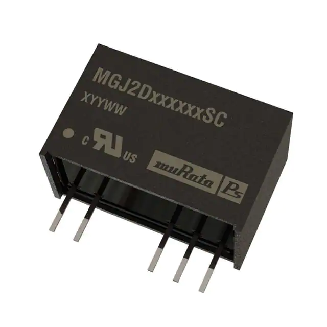
SIP package style
�
5V, 12V, 15V & 24V inputs
�
+15V/-15,V +15V/-5V, +15V/-8.7V,
+20V/-3.5 & +20V/-5V outputs
�
Operation to 100oC
�
Characterised dv/dt immunity 80kV/ȝS at
1.5kV
MGJ2D051505SC
MGJ2D051509SC
MGJ2D051515SC
MGJ2D052005SC
MGJ2D121505SC
MGJ2D121509SC
MGJ2D121515SC
MGJ2D122005SC
MGJ2D151505SC
MGJ2D151509SC
MGJ2D151515SC
MGJ2D152003SC
MGJ2D152005SC
MGJ2D241505SC
MGJ2D241509SC
MGJ2D241709SC
MGJ2D242005SC
The MGJ2 series of DC-DC converters is ideal
for powering ‘high side’ and ‘low side’ gate drive
circuits for IGBTs and Mosfets in bridge circuits.
A choice of asymmetric output voltages allows
optimum drive levels for best system efficiency
and EMI. The MGJ2 series is characterised for high
isolation and dv/dt requirements commonly seen in
bridge circuits used in motor drives and inverters,
while the MGJ2 industrial grade temperature
rating and construction gives long service life and
reliability.
%
360
390
492
440
150
155
203
195
120
130
167
150
145
75
80
105
90
5.7
6
7
6.2
4.7
5.3
6.0
5.5
5
5
5.5
7
6
4.6
4.8
6
6
7
7
8.5
8
6
7.5
7
8
7
7
7
10
8
7
7
8
8
mVp-p
30 50
30 50
20 35
30 50
30 50
30 50
24 40
30 45
30 50
30 50
23 35
30 50
30 50
30 50
30 50
30 50
30 50
%
71
73
74
74
76
76
78
78
75
76
75
76
78
75
77
78
78
pF
76 2.8
77.5 3.3
78
4
78.5 3.3
80 2.9
80 3.5
82
4
82 3.3
80 2.9
80
4
79
4
81
3
81 3.4
80.5 2.7
82 3.5
83 3.5
82 3.5
MTTF1
MIL. Tel.
kHrs
2095
1902
2629
1655
2339
2296
2707
1799
2374
2736
2100
2000 80000
1864
2194
2275
1050 47000
1725
INPUT CHARACTERISTICS
Parameter
Voltage range
�
Characterised partial discharge performance
PRODUCT OVERVIEW
80
80
67
80
80
80
67
80
80
80
67
80
80
80
80
80
80
mA
40
40
67
40
40
40
67
40
40
40
67
80
40
40
40
80
40
Isolation Capacitance
V
-5
-8.7
-15
-5
-5
-8.7
-15
-5
-5
-8.7
-15
-3.5
-5
-5
-8.7
-9V
-5
Input Current
at Rated Load
Load Regulation
(Typ)
Load Regulation
(Max)
Ripple & Noise
(Typ)2
Ripple & Noise
(Max)2
Efficiency
(Min)
Efficiency
(Typ)
V
15
15
15
20
15
15
15
20
15
15
15
20
20
15
15
17
20
Output Current 2
Reinforced insulation to UL60950
recognised3
V
5
5
5
5
12
12
12
12
15
15
15
15
15
24
24
24
24
Output Current 1
Optimised bipolar output voltages for IGBT/
Mosfet gate drives
Output Voltage 2
FEATURES
Output Voltage 1
Order Code
Nominal Input
Voltage
SELECTION GUIDE
Input reflected ripple
Conditions
Min.
Typ.
Max.
Units
Continuous operation, 5V input types
Continuous operation, 12V input types
Continuous operation, 15V input types
Continuous operation, 24V input types
5V input types
12V & 15V input types
24V input types
4.5
10.8
13.5
21.6
5
12
15
24
40
20
15
5.5
13.2
16.5
26.4
V
Typ.
Max.
mA
ISOLATION CHARACTERISTICS
Parameter
Isolation test voltage
Resistance
Conditions
Min.
Production tested for 1 second
Qualification tested for 1 minute
Viso= 500VDC
5200
5200
Units
VDC
1
GΩ
OUTPUT CHARACTERISTICS
Parameter
Conditions
TA=-40ºC to 100ºC
Rated Power
Voltage Set Point Accuracy
Line regulation
Min.
See tolerance envelopes
High VIN to low VIN
Typ.
Max.
Units
2
W
1.0
1.2
%/%
Typ.
Max.
Units
GENERAL CHARACTERISTICS
For full details go to
www.murata-ps.com/rohs
Parameter
Conditions
Switching frequency
All types
Min.
45
kHz
1. Calculated using MIL-HDBK-217 FN2 calculation model with nominal input voltage at full load.
2. See ripple & noise test method.
3. UL60950 recognition is currently pending for the MGJ2D241709SC.
4. ANSI/AAMI ES60601-1 recognition is currently pending for the MGJ2D241709SC.
All specifications typical at TA=25°C, nominal input voltage and rated output current unless otherwise specified.
www.murata-ps.com/support
KDC_MGJ2_G01Page 1 of 9
�MGJ2 Series
5.2kVDC Isolated 2W Gate Drive DC-DC Converters
TEMPERATURE CHARACTERISTICS
Parameter
Conditions
Min.
Specification
Storage
All output types (see safety approval section for limitations)
-40
-55
Typ.
Max.
Units
100
125
5V input types
24
All other input types
20
°C
Case Temperature above ambient
Cooling
Free air convection
ABSOLUTE MAXIMUM RATINGS
Short-circuit protection
Lead temperature 1mm from case for 10 seconds
Input voltage VIN, MGJ2D05xxxxSC
Input voltage VIN, MGJ2D12xxxxSC
Input voltage VIN, MGJ2D15xxxxSC
Input voltage VIN, MGJ2D24xxxxSC
Continuous
260°C
5.5V
13.2V
16.5V
26.4V
www.murata-ps.com/support
KDC_MGJ2_G01Page 2 of 9
�MGJ2 Series
5.2kVDC Isolated 2W Gate Drive DC-DC Converters
TECHNICAL NOTES
ISOLATION VOLTAGE
‘Hi Pot Test’, ‘Flash Tested’, ‘Withstand Voltage’, ‘Proof Voltage’, ‘Dielectric Withstand Voltage’ & ‘Isolation Test Voltage’ are all terms that relate to the same thing, a test
voltage, applied for a specified time, across a component designed to provide electrical isolation, to verify the integrity of that isolation.
Murata Power Solutions MGJ2 series of DC-DC converters are all 100% production tested at 5.2kVDC for 1 second and have been qualification tested at 5.2kVDC for 1
minute.
A question commonly asked is, “What is the continuous voltage that can be applied across the part in normal operation?”
When the insulation in the MGJ2 series is not used as a safety barrier , i.e. provides functional isolation only, continuous or switched voltages across the barrier in excess
of 1.5kV are sustainable. Long term reliability testing at these voltages continues. Please contact Murata for further information.
The MGJ2 series is recognised by Underwriters Laboratory for various voltages, please see safety approval section below.
REPEATED HIGH-VOLTAGE ISOLATION TESTING
It is well known that repeated high-voltage isolation testing of a barrier component can actually degrade isolation capability, to a lesser or greater degree depending on
materials, construction and environment. We therefore strongly advise against repeated high voltage isolation testing, but if it is absolutely required, that the voltage be
SAFETY APPROVAL
ANSI/AAMI ES60601-1
The MGJ2 series has been recognised by Underwriters Laboratory (UL) to ANSI/AAMI ES60601-1 and provides 1 MOOP (Means Of Operator Protection) based on a working voltage
of 300Vrms or 2 MOOP based upon a working voltage of 200 Vrms, and 1 MOPP (Mean Of Patient Protection) based on a working voltage of 200Vrms., between Primary and
Secondary. The MGJ2D241709SC is currently pending recognition.
File number E202895 applies.
UL 60950
The MGJ2 series is recognised by Underwriters Laboratory (UL) to UL 60950 for reinforced insulation to a working voltage of 150Vrms and for basic/supplementary insulation to a
working voltage of 300Vrms. The MGJ2D241709SC is currently pending recognition.
File number E151252 applies.
Creepage and clearance 3mm.
Fusing
The MGJ2 Series of converters are not internally fused so to meet the requirements of UL an anti-surge input line fuse should always be used with ratings as defined below.
MGJ2x05xxxC: 1.25A
MGJ2x12xxxC: 750mA
MGJ2x15xxxC: 750mA
MGJ2x24xxxC: 750mA
All fuses should be UL recognized and rated to 125V.
RoHS COMPLIANCE INFORMATION
This series is compatible with RoHS soldering systems with a peak wave solder temperature of 260ºC for 10 seconds. The pin termination finish
on this product series is Tin Plate, Hot Dipped over Matte Tin with Nickel Preplate. The series is backward compatible with Sn/Pb soldering
systems. For further information, please visit www.murata-ps.com/rohs
www.murata-ps.com/support
KDC_MGJ2_G01Page 3 of 9
�MGJ2 Series
5.2kVDC Isolated 2W Gate Drive DC-DC Converters
APPLICATION NOTES
Minimum load
The minimum load to meet datasheet specification is 10% of the full rated load across the specified input voltage range. Lower than 10% minimum loading will result in
an increase in output voltage, which may rise to typically 1.25 times the specified output voltage if the output load falls to less than 5%.
Capacitive loading and start up
Typical start up times for this series, with a typical input voltage rise time of 2.2μs and output capacitance of 10μF, are shown in the table below. The product
series will start into capacitance ranging from 47μF up to 220μF with increased start times.
MGJ2D051505SC
MGJ2D051509SC
MGJ2D051515SC
MGJ2D052005SC
MGJ2D121505SC
MGJ2D121509SC
MGJ2D121515SC
MGJ2D122005SC
MGJ2D151505SC
MGJ2D151509SC
MGJ2D151515SC
MGJ2D152003SC
MGJ2D152005SC
MGJ2D241505SC
MGJ2D241509SC
MGJ2D241709SC
MGJ2D242005SC
Start-up time
ms
3.3
4.5
20.84
5.4
3.2
4
14.54
5.5
2.5
3
10.48
4.5
4.5
2.7
3
4
4.2
Typical Start-Up Wave Form
Ripple & Noise Characterisation Method
Ripple and noise measurements are performed with the following test configuration.
C1
1μF X7R multilayer ceramic capacitor, voltage rating to be a minimum of 3 times the output voltage of the DC-DC converter
10μF tantalum capacitor, voltage rating to be a minimum of 1.5 times the output voltage of the DC-DC converter with an ESR of less
C2
than 100mΩ at 100 kHz
C3
100nF multilayer ceramic capacitor, general purpose
R1
450Ω resistor, carbon film, ±1% tolerance
R2
50Ω BNC termination
T1
3T of the coax cable through a ferrite toroid
RLOAD
Resistive load to the maximum power rating of the DC-DC converter. Connections should be made via twisted wires
Measured values are multiplied by 10 to obtain the specified values.
Differential Mode Noise Test Schematic
DC/DC Converter
OSCILLOSCOPE
C1 C2 C3
+
SUPPLY
Input
-
+
R1
T1
R2
Y INPUT
Output
-
R LOAD
www.murata-ps.com/support
KDC_MGJ2_G01Page 4 of 9
�MGJ2 Series
5.2kVDC Isolated 2W Gate Drive DC-DC Converters
EFFICIENCY VS LOAD
5V INPUT
12V INPUT
90
90
80
80
70
70
60
MGJ2D051505SC
50
MGJ2D051509SC
MGJ2D052005SC
40
MGJ2D051515SC
Efficiency (%)
Efficiency (%)
60
MGJ2D121509SC
MGJ2D122005SC
40
30
30
20
20
10
10
0
MGJ2D121505SC
50
MGJ2D121515SC
0
0
10
20
30
40
50
60
70
80
90
100
0
10
20
30
40
50
Load (%)
15V INPUT
70
80
90
100
24V INPUT
90
90
80
80
70
70
60
MGJ2D151505SC
MGJ2D151509SC
50
MGJ2D152003SC
MGJ2D152005SC
40
MGJ2D151515SC
Efficiency (%)
Efficiency (%)
60
Load (%)
60
MGJ2D241505SC
50
MGJ2D241709SC
30
30
20
20
10
MGJ2D241509SC
40
MGJ2D242005SC
10
0
0
10
20
30
40
50
60
70
80
90
100
0
0
10
20
30
40
Load (%)
50
60
70
80
90
100
Load (%)
TEMPERATURE DERATING GRAPHS
-40
85
0
40
Ambient Temperature (ºC)
Full Output
Current Rating
Full Output
Current Rating
Safe
Operating Area
Safe
Operating Area
-40
95
0
40
Ambient Temperature (ºC)
All other varients
Full Output
Current Rating
MGJ2D051505SC & MGJ2D052005SC
MGJ2D051515SC, MGJ2D121515SC & MGJ2D151515SC
Safe
Operating Area
-40
100
0
40
Ambient Temperature (ºC)
www.murata-ps.com/support
KDC_MGJ2_G01Page 5 of 9
�MGJ2 Series
5.2kVDC Isolated 2W Gate Drive DC-DC Converters
POSITIVE OUTPUT VOLTAGE TOLERANCE ENVELOPES
The voltage tolerance envelopes show typical load regulation characteristics for this product series. The tolerance envelope is the maximum output voltage variation due to
changes in output loading and set point accuracy.
4%
2%
1%
-4%
10
75
50
25
Output Load Current (%)
MGJ2D122005SC, MGJ2D152005SC & MGJ2D242005SC
Output Voltage
Output Voltage
MGJ2D051505SC, MGJ2D051509SC, MGJ2D151505SC
& MGJ2D151509SC
3%
2%
-1%
-5%
100
10
4%
1%
0%
MGJ2D121505SC & MGJ2D241505SC
Output Voltage
Output Voltage
MGJ2D121509SC, MGJ2D241509SC & MGJ2D052005SC
100
50
75
25
Output Load Current (%)
5%
3%
2%
-3%
-7%
10
75
50
25
Output Load Current (%)
100
10
MGJ2D121515SC & MGJ2D151515SC
50
75
25
Output Load Current (%)
100
MGJ2D152003SC
3%
1%
-4%
10
75
50
25
Output Load Current (%)
100
Output Voltage
Output Voltage
6%
4%
1%
0%
-6%
10
75
50
25
Output Load Current (%)
100
www.murata-ps.com/support
KDC_MGJ2_G01Page 6 of 9
�MGJ2 Series
5.2kVDC Isolated 2W Gate Drive DC-DC Converters
POSITIVE OUTPUT VOLTAGE TOLERANCE ENVELOPES CONTINUED
MGJ2D051515SC
MGJ2D241709SC
7%
1%
0%
Output Voltage
Output Voltage
6%
3.5%
3%
-3%
-7%
10
75
50
25
Output Load Current (%)
10
100
75
50
25
Output Load Current (%)
100
NEGATIVE OUTPUT VOLTAGE TOLERANCE ENVELOPES
MGJ2D051509SC, MGJ2D052005SC & MGJ2D121505SC, MGJ2D122005SC, MGJ2D152005SC & MGJ2D242005SC
MGJ2D151505SC
8%
6%
3%
2%
-4%
10
75
50
25
Output Load Current (%)
4%
Output Voltage
Output Voltage
7%
0%
10
100
4%
1%
1%
-6%
10
75
50
25
Output Load Current (%)
100
MGJ2D051505SC
100
Output Voltage
Output Voltage
MGJ2D121509SC & MGJ2D241509SC
75
50
25
Output Load Current (%)
5%
3%
1%
-4%
10
75
50
25
Output Load Current (%)
100
www.murata-ps.com/support
KDC_MGJ2_G01Page 7 of 9
�MGJ2 Series
5.2kVDC Isolated 2W Gate Drive DC-DC Converters
NEGATIVE OUTPUT VOLTAGE TOLERANCE ENVELOPES CONTINUED
MGJ2D151509SC & MGJ2D241505SC
MGJ2D121515SC & MGJ2D151515SC
6%
3%
2%
-3%
10
75
50
25
Output Load Current (%)
Output Voltage
Output Voltage
6%
3%
1%
-4%
10
100
MGJ2D051515SC
75
50
25
Output Load Current (%)
100
MGJ2D152003SC
8%
1%
0%
Output Voltage
Output Voltage
6%
4%
3%
-4%
-7%
10
75
50
25
Output Load Current (%)
10
100
75
50
25
Output Load Current (%)
100
MGJ2D241709SC
Output Voltage
6.5%
3%
2%
-4%
10
75
50
25
Output Load Current (%)
100
www.murata-ps.com/support
KDC_MGJ2_G01Page 8 of 9
�MGJ2 Series
5.2kVDC Isolated 2W Gate Drive DC-DC Converters
PACKAGE SPECIFICATIONS
MECHANICAL DIMENSIONS
PIN CONNECTIONS
Pin Output
All dimensions in mm ±0.25mm (inches ±0.01). All pins on a 2.54 (0.1) pitch and within
±0.25 (0.01) of true position.
TUBE OUTLINE DIMENSIONS
Unless otherwise stated all dimensions in mm ±0.5mm (inches ±0.02).
Tube length : 20.669±0.079 (525mm±2mm).
Pin
Function
1
2
5
6
7
+VIN
-VIN
-VOUT
OV
+VOUT
Weight: 4.3g
RECOMMENDED FOOTPRINT DETAILS
Tube Quantity : 25
All dimensions in mm ±0.25mm (inches ±0.01).
This product is subject to the following operating requirements
and the Life and Safety Critical Application Sales Policy:
Refer to: http://www.murata-ps.com/requirements/
Murata Power Solutions, Inc. makes no representation that the use of its products in the circuits described herein, or the use of other
technical information contained herein, will not infringe upon existing or future patent rights. The descriptions contained herein do not imply
the granting of licenses to make, use, or sell equipment constructed in accordance therewith. Specifications are subject to change without
notice.
© 2018 Murata Power Solutions, Inc.
www.murata-ps.com/support
KDC_MGJ2_G01Page 9 of 9
�


 工商网监
湘ICP备2023018690号
工商网监
湘ICP备2023018690号

