MPDTY303S DATA Sheet
1
DC-DC Converter DATA Sheet
2010.12.29 DATE2010.12.29 ¥@ "yyyy.M.d" 2010.12.14
MPDTY303S
1. Features
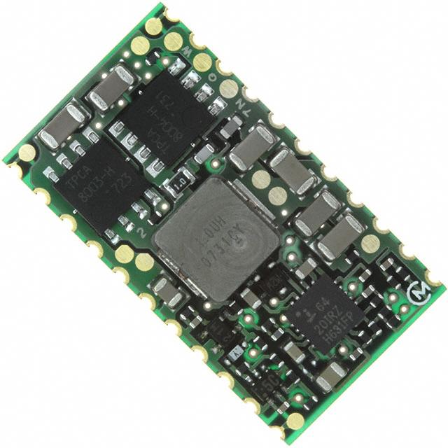
These are the Low Voltage/High current non-insulated type
DC-DC Converter.
Low profile; 4.2mmMAX.
o
o
Wide operating temperature (-40 C~+85 C).
Output voltage is adjustable by using single external resistance (0.8-5.5V).
ON/OFF function is built in.
Output voltage sense function is built in.
Short circuit protection & over temperature protection is built in.
2. Appearance, Dimensions
15.4±0.2
22
P
P
P
27.8±0.2
P
P
P
P
P
P
P
P
P
1
P
A
P
□
□
B
P=2.54 ±0.3mm
Tolerance is not accumulated.
【Unit:mm】
P
P
Marking
(1) Pin Nokg / MFG ID
(2) Part No.
QW
(3) Lot No.
AB
A : Production Year
B : Production Month(1,2,3,…9,O,N,D)
P
P
Q
P
P
W
11
12
Pin Number and Function
Pin No.
Symbol
1,2,3,4,5
Vout
6,7,8,9,10,
GND
18,19,20,21
11
VAR
12
ON/OFF
13,14,15,16,17
Vin
22
SENSE
4.2max.
Function
Output
GND
Output voltage adjustment
Remote ON/OFF
Input
Output voltage sense
Note:
1. This datasheet is downloaded from the website of Murata Manufacturing co., ltd. Therefore, it’ s specifications are subject to change or our
products in it may be discontinued without advance notice. Please check with our sales representatives or product engineers before ordering.
2. This datasheet has only typical specifications because there is no space for detailed specifications. Therefore, please approve our product
specifications or transact the approval sheet for product specifications before ordering.
2010.12.29
�MPDTY303S DATA Sheet
2
2010.12.29 DATE2010.12.29 ¥@ "yyyy.M.d" 2010.12.142010.12.29
3. Block Diagram
Vin
Vout
13,14,15,16,17
1,2,3,4,5
SENSE
18,19,20,21
GND
GND
ON/OFF
12
22
6,7,8,9,10
11
Control Circuit
VAR
4. Environmental Conditions
4 .1
4 .2
4 .3
4 .4
4 .5
4 .6
6.5V – 14Vo
o
-40 to +85 C(Temperature gradient ≦10 C /H)
o
o
-45 to +90 C(Temperature gradient ≦25 C /H)
10% ~ 85%(No water condenses in any cases.)
10% ~ 90%(No water condenses in any cases.)
39°C
Input Voltage Range
Operating Temperature Range
Storage Temperature Range
Operating Humidity Range
Storage Humidity Range
Maximum Wet Bulb
5. Absolute Maximum Rating
Item
Minimum Input Voltage
Maximum Input Voltage
ON/OFF Pin Voltage
Unit
V
V
V
Absolute Rating
0
14
Vin
Remarks
※No voltage, no matter how instantaneous, shall be applied beyond the absolute maximum voltage rating to this
product. If you apply any voltage over this limit the product characteristics will deteriorate or the product itself will be
destroyed. Even though it may continue operating for a while after the over-voltage event, its life will likely be shortened
significantly. Reliability and life of the module may degrade similarly if the maximum operating voltage rating is
continuously exceeded. This product is designed to operate within the maximum operating voltage rating specification.
Note:
1. This datasheet is downloaded from the website of Murata Manufacturing co., ltd. Therefore, it’ s specifications are subject to change or our
products in it may be discontinued without advance notice. Please check with our sales representatives or product engineers before ordering.
2. This datasheet has only typical specifications because there is no space for detailed specifications. Therefore, please approve our product
specifications or transact the approval sheet for product specifications before ordering.
2010.12.29
�MPDTY303S DATA Sheet
3
6. Characteristics
o
6.1 Electrical Characteristics (Ta=25 C)
Value
Item
Symbol
Condition
Min.
Typ.
Max.
Unit
Input Voltage Range
Vin
6.5
-
14
V
UVLO Threshold
UVLO
5.5
-
6.5
V
Output Voltage
Adjustable Range
Vout
0.8
-
5.5
V
0.80
0.824
Static Output
Voltage Accuracy
Vin-Vout>2.5V
Vout-0.8
Vin =6.5 - 13.2V, Iout= 0 - 8A
VAR= Open, ON/OFF= Open
0.776
Vout-5.5
Vin =8.0 - 13.2V, Iout= 0 -8A
VAR= 311Ω, ON/OFF= Open
5.335
5.50
5.665
0
-
8
A
V
Output Current
Iout
See thermal derating curve
Ripple Voltage
Vrpl
Vin =12V, Vout=3.3V, Ta=25 C
Iout=8A, BW=20MHz, Cout=44μF
-
25
50
mV(p_p)
Efficiency
η
Vin =12V, Vout=3.3V, Iout= 8A,
o
Ta=25 C
-
92
-
%
-
530
-
kHz
o
Operating Frequency
ON/OFF pin is connected to soft-start capacitor inside of this product. If ON/OFF
pin is left open, this product shall be “ON”. This pin will be pulled down to GND
inside the product when OCP or OTP events occur. Please do NOT connect this
pin to Vin, so as not to damage the converter.
If ON/OFF pin is pulled down to GND,
0
0.7
V
this product shall be “OFF”.
ON/OFF pin High Voltage
VIH
ON/OFF pin Low Voltage
VIL
Short Circuit Protection
SCP
Reset, Followed by Auto-Recovery
8.5
15
-
Over Temperature
Protection
OTP
Reset, Followed by Auto-Recovery
-
115
-
Addirional Output Capacitor
Cout
When input voltage is ideal voltage
source
44
-
1000
µF
Rising Overshoot
Vover
-
-
+10
%
Output Delay
Td
Output Voltage 0-10% (remote on)
-
8
20
msec
Output Rise Time
Tr
Output Voltage 10-90%
-
3
10
msec
A
o
C
※Caution
1.The above electrical characteristics are guaranteed in the condition that the impedance of the input voltage
source is sufficiently low as shown in clause 9. Connecting an input inductance or using an input power
supply with output inductance may cause an unstable operation of this product. Please check the proper operation
of this product with the peripheral circuits on your product.
2.Connecting a LC filter to Vout and connecting the SENSE pin to the output of the LC filter may cause an
unstable operation of this product because of the delay of the LC filter. Please check the proper operation
of this product with the peripheral circuits on your product.
3.This product is not pre-bias compatible. This product will boost back the output voltage to the input voltage in
start-up period and stop-down period. Please use a power supply that can sink current as the input voltage
supply. If not so, please connect a sufficient capacitor to absorb the boost back current and check that the input
voltage stays within the input voltage range.
Note:
1. This datasheet is downloaded from the website of Murata Manufacturing co., ltd. Therefore, it’ s specifications are subject to change or our
products in it may be discontinued without advance notice. Please check with our sales representatives or product engineers before ordering.
2. This datasheet has only typical specifications because there is no space for detailed specifications. Therefore, please approve our product
specifications or transact the approval sheet for product specifications before ordering.
2010.12.29
�MPDTY303S DATA Sheet
4
2010.12.29 DATE2010.12.29 ¥@ "yyyy.M.d" 2010.12.142010.12.29
6.2 Thermal Derating
MPDT303S Thermal Derating
[ Vin=9V , Vout=5.5V ]
9
8
7
6
5
4
3
2
1
0
0m/s
0.5m/s
1.0m/s
2.0m/s
20
30
40
50
60
70
80
Output Current [A]
Output Current [A]
MPDT303S Thermal Derating
[ Vin=12V , Vout=5.5V ]
9
8
7
6
5
4
3
2
1
0
90
0m/s
0.5m/s
1.0m/s
2.0m/s
20
30
40
Ta [℃]
0.5m/s
1.0m/s
2.0m/s
50
60
70
80
Output Current [A]
Output Current [A]
0m/s
40
90
0.5m/s
1.0m/s
2.0m/s
20
30
40
1.0m/s
2.0m/s
60
70
80
90
Output Current [A]
Output Current [A]
0.5m/s
Ta [℃]
60
70
80
90
MPDT303S Thermal Derating
[ Vin=9V , Vout=1.5V ]
0m/s
50
50
Ta [℃]
9
8
7
6
5
4
3
2
1
0
40
90
0m/s
MPDT303S Thermal Derating
[ Vin=12V , Vout=1.5V ]
30
80
9
8
7
6
5
4
3
2
1
0
Ta [℃]
20
70
MPDT303S Thermal Derating
[ Vin=9V , Vout=3.3V ]
9
8
7
6
5
4
3
2
1
0
30
60
Ta [℃]
MPDT303S Thermal Derating
[ Vin=12V , Vout=3.3V ]
20
50
9
8
7
6
5
4
3
2
1
0
0m/s
0.5m/s
1.0m/s
2.0m/s
20
30
40
50
60
70
80
90
Ta [℃]
The above derating limits apply to this product soldered directly to 101.6×180mm×1.6mm PCB (double-sided,
with 70um copper). Any adjacent parts of high temperature or difference of PCB design may cause overheat
o
of this product. For reliable operation, please check that the FETs temperature of this product is below 120 C,
o
and the inductor temperature of this product is below 110 C.
Note:
1. This datasheet is downloaded from the website of Murata Manufacturing co., ltd. Therefore, it’ s specifications are subject to change or our
products in it may be discontinued without advance notice. Please check with our sales representatives or product engineers before ordering.
2. This datasheet has only typical specifications because there is no space for detailed specifications. Therefore, please approve our product
specifications or transact the approval sheet for product specifications before ordering.
2010.12.29
�MPDTY303S DATA Sheet
5
7. Operation in information
7.1 Adjusting the Output Voltage
The output voltage can be adjusted ranging from 0.8V to 5.5V by connecting resistors between VAR-pin(11pin)
to GND-pin.The following equation gives the required external-resistor value to adjust the output voltage to Vout.
Please use this product on the condition Vin>Vout+2.5V
Internal circuit
MPDTY303S
Vout
10
SENSE pin
19800
RVAR=
33k
VAR pin
-3900[]
Voadj[V]-0.798[V]
3.9k
Error amp
RVAR
100k
RVAR calculation example
Voadj [V]
Calculated RVAR [Ω]
5.5
311
RVAR example
300
5.0
812
680 + 120
3.3
2.5
4013
7733
3.9k + 110
7.5k + 220
2.0
1.8
12573
15861
12k + 560
15k + 820
1.5
24305
24k + 300
1.2
1.0
45354
94120
39k + 6.2k
82k + 12k
0.8
9896100
Open
Note:
1. This datasheet is downloaded from the website of Murata Manufacturing co., ltd. Therefore, it’ s specifications are subject to change or our
products in it may be discontinued without advance notice. Please check with our sales representatives or product engineers before ordering.
2. This datasheet has only typical specifications because there is no space for detailed specifications. Therefore, please approve our product
specifications or transact the approval sheet for product specifications before ordering.
2010.12.29
�MPDTY303S DATA Sheet
6
7.2 ON/OFF Control
ON/OFF function
The DC-DC Converter can be inactive by using ON/OFF function.
This function is effective when the sequence of a power supply system is constituted.
And it can be used for power-saving control.
In case of not using ON/OFF function
In case of not using ON/OFF function, please left open ON/OFF-pin(12pin).
If ON/OFF pin is connected to Vin with low impedance line, OCP and OTP shall be inactive.
ON/OFF control method
Between ON/OFF-pin(12pin) and GND-pin
Open……Output Voltage=ON
Short……Output Voltage=OFF
TY303S
6-10,18-21
12
使用例
example
GND
ON/OFF
or
8. Reliability
8.1 Humidity
According to JIS-C-0022.
40 土 2°C, 90 to 95%RH, 100 hours. Leave for 4 hours at room temperature.
No damage in appearance and no deviation from electrical characteristics (section 6.1).
8.2 Temperature Cycles
Repeat cycle 5 times. Leave 2 hours at room temp.
No damage in appearance and no deviation from electrical characteristics (section 6.1).
Step
Condition
Time
1
-40°C±3°C
30 minutes
2
Room Temp.
5-10 minutes
3
+85°C±2°C
30 minutes
4
Room Temp.
5-10 minutes
8.3 Vibration
10 to 55Hz, 1.5mm amplitude (1minute cycle), 1 hour for each of X, Y, Z directions.
No damage in appearance and no deviation from electrical characteristics (section 6.1).
8.4 Mechanical Shock
20G, 1 time for each X, Y, Z directions.
No damage in appearance and no deviation from electrical characteristics (section 6.1).
Note:
1. This datasheet is downloaded from the website of Murata Manufacturing co., ltd. Therefore, it’ s specifications are subject to change or our
products in it may be discontinued without advance notice. Please check with our sales representatives or product engineers before ordering.
2. This datasheet has only typical specifications because there is no space for detailed specifications. Therefore, please approve our product
specifications or transact the approval sheet for product specifications before ordering.
2010.12.29
�MPDTY303S DATA Sheet
7
9. TestDATE2010.12.29
Circuit
2010.12.29
¥@ "yyyy.M.d" 2010.12.142010.12.29
Using the following test circuit, the initial values under section 6.1 sall be met.
9.1. General Measure Circuit
Vin
13,14,15,16,17
ON/OFF
12
C1
Vout
1,2,3,4,5
SENSE
MPDTY303S
22
6,7,8,9,10,
18,19,20,21
11
VAR
RL
C2
C3
RVAR
C1~C3
:
22μF/16V
(Ceramic Capacitor)
Ripple Noise Measurement Circuit
Coaxial cable :1.5D-2V, L=1.5m
Oscilloscope
BW:20MHz
Vout
DC-DC Converter
GND
Terminator
(Keisokugiken TRC-50F)
44μF ceramic cap
Equivalent circuit
R:50
C:0.01μF
B
A
A:Output Ripple Noise
B:Output Ripple Voltage
Note:
1. This datasheet is downloaded from the website of Murata Manufacturing co., ltd. Therefore, it’ s specifications are subject to change or our
products in it may be discontinued without advance notice. Please check with our sales representatives or product engineers before ordering.
2. This datasheet has only typical specifications because there is no space for detailed specifications. Therefore, please approve our product
specifications or transact the approval sheet for product specifications before ordering.
2010.12.29
�MPDTY303S DATA Sheet
8
2010.12.29 DATE2010.12.29 ¥@ "yyyy.M.d" 2010.12.142010.12.29
24.0±0.1
4.0±0.1
(26.4)
20.2±0.1
2.0±0.15
(4.6)
0.4±0.05
44.0±0.3
+0.1
-0
40.4±0.1
1.5
1.75±0.1
10. Packaging Specification
10.1 Embossed Tape Dimensions
(16)
Pulling direction
+0.1
-0
+0.1
-0
1.7
0.2
1.5
10.2 Reel Dimension
49.4±1.0
45.4±1.0
φ 100±1
φ 330±2
A
2.0±0.5
表示
Indication
φ 21.0±0.8
φ 13.0±0.5
A部詳細図
Portion A
Note:
1. This datasheet is downloaded from the website of Murata Manufacturing co., ltd. Therefore, it’ s specifications are subject to change or our
products in it may be discontinued without advance notice. Please check with our sales representatives or product engineers before ordering.
2. This datasheet has only typical specifications because there is no space for detailed specifications. Therefore, please approve our product
specifications or transact the approval sheet for product specifications before ordering.
2010.12.29
�MPDTY303S DATA Sheet
9
10.3 Taping Specification
Empty portion
(200mm MIN)
Empty portion
(200mm MIN)
Leader portion
(200mm MIN)
"Module on tape" portion
Indication
1pin
1pin
Pulling
Pullingdirection
direction
The module
is located
such
coil in
andand
pinssubstrate
in lower side.
The module
is located
such
asasparts
inupper
upperside
side
in lower side.
10.4 Note
1. The adhesive strength of the protective tape must be within 0.1-1N.
2. Each reel contains 300pcs.
3. The deficiency per reel is 0 piece.
4. The reel shows customer part number, Murata part number and quantity.
5. The color of reel is not designated.
11. Production factory
Komatsu Murata Mfg.Co., Ltd.
Kanazu Murata Mfg. Co., Ltd.
Wakura Murata Mfg. Co., Ltd.
Note:
1. This datasheet is downloaded from the website of Murata Manufacturing co., ltd. Therefore, it’ s specifications are subject to change or our
products in it may be discontinued without advance notice. Please check with our sales representatives or product engineers before ordering.
2. This datasheet has only typical specifications because there is no space for detailed specifications. Therefore, please approve our product
specifications or transact the approval sheet for product specifications before ordering.
2010.12.29
�MPDTY303S DATA Sheet
10
12. Characteristics Data
o
12.1.1 Vout=0.8V
( Ta=25 C, Iomax=8A, Cout=44μF )
Static Load Regulation
0.824
0.816
Vo1 [V]
0.808
Vin=6.5V
Vin=9V
Vin=12V
Vin=14V
0.800
0.792
0.784
0.776
0
20
40
60
80
100
Io/Iomax [%]
Vr1 [mVp-p]
Output Ripple Noise
50
45
40
35
30
25
20
15
10
5
0
Vin=6.5V
Vin=9V
Vin=12V
Vin=14V
0
20
40
60
80
100
Io/Iomax [%]
Efficiency
90
85
Eff [%]
80
Ta=25℃ Vin=6.5V
Ta=25℃ Vin=9V
Ta=25℃ Vin=12V
Ta=25℃ Vin=14V
75
70
65
60
0
20
40
60
80
100
Io/Iomax [%]
Note:
1. This datasheet is downloaded from the website of Murata Manufacturing co., ltd. Therefore, it’ s specifications are subject to change or our
products in it may be discontinued without advance notice. Please check with our sales representatives or product engineers before ordering.
2. This datasheet has only typical specifications because there is no space for detailed specifications. Therefore, please approve our product
specifications or transact the approval sheet for product specifications before ordering.
2010.12.29
�MPDTY303S DATA Sheet
11
2010.12.29 DATE2010.12.29 ¥@ "yyyy.M.d"
o 2010.12.142010.12.29
12.1. 2 Vout=1.5V
( Ta=25 C, Iomax=8A, Cout=44μF )
Static Load Regulation
1.545
1.530
Vo1 [V]
1.515
Vin=6.5V
Vin=9V
Vin=12V
Vin=14V
1.500
1.485
1.470
1.455
0
20
40
60
80
100
Io/Iomax [%]
Vr1 [mVp-p]
Output Ripple Noise
50
45
40
35
30
25
20
15
10
5
0
Vin=6.5V
Vin=9V
Vin=12V
Vin=14V
0
20
40
60
80
100
Io/Iomax [%]
Efficiency
95
Eff [%]
90
Ta=25℃ Vin=6.5V
Ta=25℃ Vin=9V
Ta=25℃ Vin=12V
Ta=25℃ Vin=14V
85
80
75
70
0
20
40
60
80
100
Io/Iomax [%]
Note:
1. This datasheet is downloaded from the website of Murata Manufacturing co., ltd. Therefore, it’ s specifications are subject to change or our
products in it may be discontinued without advance notice. Please check with our sales representatives or product engineers before ordering.
2. This datasheet has only typical specifications because there is no space for detailed specifications. Therefore, please approve our product
specifications or transact the approval sheet for product specifications before ordering.
2010.12.29
�MPDTY303S DATA Sheet
12
2010.12.29 DATE2010.12.29 ¥@ "yyyy.M.d"
o 2010.12.142010.12.29
12. 1.3 Vout=3.3V
( Ta=25 C, Iomax=8A, Cout=44μF )
Static Load Regulation
3.399
3.366
Vo1 [V]
3.333
Vin=6.5V
Vin=9V
Vin=12V
Vin=14V
3.300
3.267
3.234
3.201
0
20
40
60
80
100
Io/Iomax [%]
Vr1 [mVp-p]
Output Ripple Noise
50
45
40
35
30
25
20
15
10
5
0
Vin=6.5V
Vin=9V
Vin=12V
Vin=14V
0
20
40
60
80
100
Io/Iomax [%]
Efficiency
100
Eff [%]
95
Ta=25℃ Vin=6.5V
Ta=25℃ Vin=9V
Ta=25℃ Vin=12V
Ta=25℃ Vin=14V
90
85
80
75
0
20
40
60
80
100
Io/Iomax [%]
Note:
1. This datasheet is downloaded from the website of Murata Manufacturing co., ltd. Therefore, it’ s specifications are subject to change or our
products in it may be discontinued without advance notice. Please check with our sales representatives or product engineers before ordering.
2. This datasheet has only typical specifications because there is no space for detailed specifications. Therefore, please approve our product
specifications or transact the approval sheet for product specifications before ordering.
2010.12.29
�MPDTY303S DATA Sheet
13
2010.12.29 DATE2010.12.29 ¥@ "yyyy.M.d"
o 2010.12.142010.12.29
12.1.4 Vout=5.5V
( Ta=25 C, Iomax=8A, Cout=44μF )
Static Load Regulation
5.665
5.610
Vo1 [V]
5.555
Vin=8V
Vin=9V
Vin=12V
Vin=14V
5.500
5.445
5.390
5.335
0
20
40
60
80
100
Io/Iomax [%]
Vr1 [mVp-p]
Output Ripple Noise
50
45
40
35
30
25
20
15
10
5
0
Vin=8V
Vin=9V
Vin=12V
Vin=14V
0
20
40
60
80
100
Io/Iomax [%]
Efficiency
100
98
Eff [%]
96
94
92
Ta=25℃ Vin=8V
Ta=25℃ Vin=9V
Ta=25℃ Vin=12V
Ta=25℃ Vin=14V
90
88
86
84
82
0
20
40
60
80
100
Io/Iomax [%]
Note:
1. This datasheet is downloaded from the website of Murata Manufacturing co., ltd. Therefore, it’ s specifications are subject to change or our
products in it may be discontinued without advance notice. Please check with our sales representatives or product engineers before ordering.
2. This datasheet has only typical specifications because there is no space for detailed specifications. Therefore, please approve our product
specifications or transact the approval sheet for product specifications before ordering.
2010.12.29
�MPDTY303S DATA Sheet
14
2010.12.29 DATE2010.12.29 ¥@ "yyyy.M.d" 2010.12.142010.12.29
13. Mounting Condition
13.1. Recommendable Solder Land Pattern
8.0
1pin
1.2
1.4
1.0
1.5
2.54
There are wiring coppers or through-hole via
at the bottom side of the DC-DC Converter.
When you design your PCBs, please be careful
not to short the circuit of the DC-DC Converter or PCBs.
1.2
4.0
3.3
13.2. Recommendable Condition of Soldering
This product is RoHS compatible. The following profile is recommended for the reflow of this
product using Pb-free solder paste (Sn-Ag-Cu).
Method
:
Full convection reflow soldering
Reflow Soldering Profile
JEDEC IPC/JEDEC J-STD-020D
Table 5-2 Classification Reflow Profile
Pb-Free Assembly Large Body
Profile details
Soldering temperature
Soldering time
Heating time
Preheating time
Programming rate
Descending rate
Total soldering time
Times
o
o
: 245 C +0/-5 C
o
: 30 seconds, 240 to 245 C
o
: 60 to 150 seconds, over217 Co
: 60o to 120 seconds,150 to 200
C
o
: 3 C / sec. Max.,217 to 245 C
o
: 6 C / sec. Max.
o
: 8 minutes Max., 25 to 245 C
: 1time
245oC
o
Parts surface temperature [ C]
217oC
200oC
60~150
(seconds)
150oC
60~120(seconds)
Times
※Do not add vibration to this product during reflow.
Please carefully regulate temperature control as mounted parts may come off from this product
if left under the high temperature for an extended time.
Note:
1. This datasheet is downloaded from the website of Murata Manufacturing co., ltd. Therefore, it’ s specifications are subject to change or our
products in it may be discontinued without advance notice. Please check with our sales representatives or product engineers before ordering.
2. This datasheet has only typical specifications because there is no space for detailed specifications. Therefore, please approve our product
specifications or transact the approval sheet for product specifications before ordering.
2010.12.29
�MPDTY303S DATA Sheet
15
2010.12.29 DATE2010.12.29 ¥@ "yyyy.M.d" 2010.12.142010.12.29
14. Notice
14.1. Input / output capacitor
When an inductance or a switch devise is connected to the input line, or when you use a power supply with
output inductance as the input voltage source, the input voltage of the DC-DC converter will be fluctuated.
By this input voltage fluctuation, the transient load response of the DC-DC converter may be deteriorated or
abnormal oscillation may occur. So please confirm normal operation on each application.
Please use external input capacitor in order to decrease inductance of input line.
In case you use external output capacitor in order to improve transient load response, please use input
capacitor to prevent abnormal oscillation. When you use external capacitors, following capacitors
are recommendable.
※Input capacitor C1 : Please use capacitors more than 22μF of low impedance in high frequency range.
Output capacitor C2, C3 : Please use ceramic capacitors more than 22μF ( total 44μF ).
Total capacitance of external output capacitors should be less than 1000μF.
14.2. Output LC filter
Connecting a LC filter to Vout and connecting the SENSE pin to the output of the LC filter may cause an
unstable operation of this product because of the delay of the LC filter. Please check the proper operation
of this product with the peripheral circuits on your product.
14.3. Pre-bias start up
This product is not pre-bias compatible. This product will boost back the output voltage to the input voltage
in start-up period and stop-down period. Please use a power supply that can sink current as the input
voltage supply. If not so, please connect a sufficient capacitor to absorb the boost back current and check
that the input voltage stays within the input voltage range.
14.4. Wiring of input / output capacitor
In the case of input / output capacitor connection, in order to reduce electrical noise, please design PCBs
with consideration of the following item.
①.Please be sure to check normal operation on your system.
②.Please use low impedance capacitors with good high frequency characteristic.
③.Please shorten those leads of each capacitor as much as possible, and make sure the lead inductance low.
④.Both input-side and output side, please make the wiring loop between plus and minus as small as possible.
The influence of leakage inductance can be reduced.
⑤.Please design the print pattern of the main circuit as wide and short as possible.
Make wiring roop small
Make wiring roop small
+Vin
+Vin
+Vout
DC-DC
Converter
+Vout
+Vin
Load
-Vin
C1
GND
C2
shorten the leads and pattern
shorten the leads and pattern
14.5. This product could not be operated parallel or series.
14.6. Please do not use a connector or a socket for connection with your board of this product.
Electrical performance may be deteriorated the influence of contact resistance.
Please be sure to mount this product with solder.
Note:
1. This datasheet is downloaded from the website of Murata Manufacturing co., ltd. Therefore, it’ s specifications are subject to change or our
products in it may be discontinued without advance notice. Please check with our sales representatives or product engineers before ordering.
2. This datasheet has only typical specifications because there is no space for detailed specifications. Therefore, please approve our product
specifications or transact the approval sheet for product specifications before ordering.
2010.12.29
�MPDTY303S DATA Sheet
16
14.7. Be sure to provide an appropriate fail-safe function on your product to prevent a second damage that may be
caused by the abnormal function or the failure of our product.
14.8. Please connect the input terminal with proper polarity.If you connect wrong polarity, the DC-DC Converter
may be broken. In the case of the DC-DC Converter is damaged, abnormal input current may flow in, and
abnormal overheat of the DC-DC Converter, or some damage of your products may occur. Please use a diode
and a fuse to as following figure.
fuse
+
+
OUT
diode
-
+
Load
-
※Please select diode and fuse after confirming the operation.
14.9 Cleaning
Please use no-clean type flux and do not wash this product.
14.10 Storage
14.10.1 This product does not
need to be baked before reflow process in condition that it is stored less than
o
1 year at below 30 C / 60%R.H. and is reflowed at the recommendable condition of soldering,
which is described at 13.2.
In case you store them over the limit, please bake this product
before
soldering.
o
o
If these are unpacked condition, please bake them at 125 C±5 C / 24hour. If these are packed in a
o
tape, please bake them before soldering at 40 C / 5%/ 192hour.
Avoid damp heated places or such places where there are large temperature changes, because
water may condense on the products, the characteristics may be reduced in quality, and/or be
degraded in the solderability.
If you store the products for a long time (more than 1 year), the products may be degraded in
solderability and may be rusty. Please confirm solderability for the products regularly.
14.10. 2 Please do not store the products in the places such as in a dusty place, in a place exposed directly to
sea breeze, in an atmosphere containing corrosive gas (Cl2,NH3,SO2,NOX and so on)
14.11 Operational Environment and Operational Conditions
14.11.1 Operational Environment
The products are not waterproof, chemical-proof or rust-proof.
In order to prevent leakage of electricity and abnormal temperature increase of the products,
do not use the products under the following circumstances:
(1) in an atmosphere containing corrosive gas (Cl2, NH3, SO2, NOX and so on)
(2) in a dusty place
(3) in a place exposed to direct sunlight
(4) in such a place where water splashes or in such a humid place where water condenses
(5) in a place exposed to sea breeze
(6) in any other places similar to the above (1)through (5)
14.11.2
Operational Conditions
Please use the products within specified values (power supply, temperature, input, output and load
condition, and so on). Input voltage drop for line impedance, so please make sure that input voltage is
included in specified values.
If you use the products over the specified values, it may break the products, reduce the quality, and even
if the products can endure the condition for short time, it may cause degradation of the reliability.
Note:
1. This datasheet is downloaded from the website of Murata Manufacturing co., ltd. Therefore, it’ s specifications are subject to change or our
products in it may be discontinued without advance notice. Please check with our sales representatives or product engineers before ordering.
2. This datasheet has only typical specifications because there is no space for detailed specifications. Therefore, please approve our product
specifications or transact the approval sheet for product specifications before ordering.
2010.12.29
�MPDTY303S DATA Sheet
17
14.11.3
Note prior to use
If you apply high static electricity, over rated voltage or reverse voltage to the products, it may
cause defects in the products or degrade the reliability.
Please avoid the following items:
(1) over rating power supply, reverse power supply or not-enough connection of 0 V(DC)line
(2) electrostatic discharge by production line and/or operator
(3) electrified product by electrostatic induction
Do not give an excessive mechanical shock.
If you drop the products on the floor, etc., it may occur a crack to the core of inductors and monolithic
ceramic capacitors.
Do not give a strong shock such as a drop in handling.
14.12 Transportation
If you transport the products, please pack them so that the package will not be damaged by mechanical
vibration or mechanical shock, and please educate and guide a carrier to prevent rough handling.
If you transport the products to overseas (in particular, by sea), it is expected that the transportation
environment will be the worst, so please pack the products, in the package designed on the consideration
of mechanical strength, vibration-resistant and humidity-resistant .
The package of the products which Murata sells in Japan, may not resist over seas transport .
Please consult us if you are to use the Murata package of the products sold in Japan for transport
to overseas.
!
Note
1 Murata recommends that customers ensure that the evaluation and testing of these devices are completed
with this product actually assembled on their product.
2 Please contact our main sales office or local sales office before using Murata’s products for the applications
listed below. These applications are known to require especially high reliability for the prevention of defects
which might directly cause damage to a third party’s life, body or property.
①Aircraft equipment
②Aerospace equipment
③Undersea equipment
④Power plant control equipment
⑤Medical equipment
⑥Transportation equipment (vehicles, trains, ships, etc.)
⑦Traffic signal equipment
⑧Disaster prevention /crime prevention equipment
⑨Data-processing equipment
⑩Application of similar complexity and/or reliability requirements to the applications listed in the above.
This DATA Sheet is indicated in Aug. 2005. The content is subject to change without notice.
Please confirm specifications before ordering. If there are questions regarding the content,
please contact our main or local sales office.
Note:
1. This datasheet is downloaded from the website of Murata Manufacturing co., ltd. Therefore, it’ s specifications are subject to change or our
products in it may be discontinued without advance notice. Please check with our sales representatives or product engineers before ordering.
2. This datasheet has only typical specifications because there is no space for detailed specifications. Therefore, please approve our product
specifications or transact the approval sheet for product specifications before ordering.
2010.12.29
�