MPDTY311S,MPDTY312S DATA Sheet
1
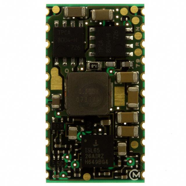
DC-DC Converter DATA Sheet
MPDTY311S/MPDTY312S
1. Features
These are the Low Voltage/High current non-insulated type
DC-DC converter.
Low profile ; 4.2mmMAX.
Output voltage is adjustable by using single external resistance.
(0.8-3.3V : MPDTY311S
0.8-2.5V : MPDTY312S )
ON/OFF function is built in.
Short circuit protection & over temperature protection is built in.
Product line up
Input Voltage
5.0V type
MPDTY311S
3.3V type
MPDTY312S
2. Appearance, Dimensions
15.4±0.2
P=2.54 ±0.3mm
22
Tolerance is not accumulated.
【Unit:mm】
P
P
P
Marking
(1) Pin No.1 Marking
(2) Parts No.
(3) Lot No
MFG ID
RN
□□
①②
①Production Year
②Production Month(1,2,3,…9,O,N,D)
P
P
①②
□
□
P
P
P
P
P
27.8±0.2
P
P
P
P
P
P
P
1
M
P
P
/
P
P
F
12
11
4.2max.
Pin Number and Function
Pin No.
Symbol
1,2,3,4,5
Vout
Function
Output
6,7,8,9,10,
18,19.20,21
GND
GND
11
12
13,14,15,16,17
22
VAR
ON/OFF
Vin
N.C.
Output voltage adjustment
Remote ON/OFF
Input
This pin must be left open.
Note:
1. This datasheet is downloaded from the website of Murata Manufacturing co., ltd. Therefore, it’ s specifications are subject to change or our
products in it may be discontinued without advance notice. Please check with our sales representatives or product engineers before ordering.
2. This datasheet has only typical specifications because there is no space for detailed specifications. Therefore, please approve our product
specifications or transact the approval sheet for product specifications before ordering.
2010.12.20
�MPDTY311S,MPDTY312S DATA Sheet
2
2010.12.20
3. Block Diagram
13,14,15,16,17
Vout
Vin
1,2,3,4,5
GND
18,19,20,21
6,7,8,9,10
GND
ON/OFF
12
11
Control Circuit
22
VAR
N.C.
4. Environmental Conditions
4 .1 Operating Temperature Range
4 .2 Storage Temperature Range
4 .3 Operating Humidity Range
4 .4 Storage Humidity Range
o
o
-40 C ~ +85 C
o
o
-45 C ~ +90 C
20% ~ 85%(No water condenses in any cases.)
o
Maximum wet-bulb temperature 39 C
10% ~ 90%(No water condenses in any cases.)
o
Maximum wet-bulb temperature 39 C
5. Absolute Rating
Item
Unit
Absolute Rating
V
0
MPDTY311S
V
5.5
MPDTY312S
V
3.6
V
Vin+0.3
Minimum Input Voltage
Remarks
Maximum Input Voltage
VAR,ON/OFF
Pin Voltage
※No voltage, no matter how instantaneous, shall be applied beyond the absolute maximum voltage rating to this
product. If you apply any voltage over this limit the product characteristics will deteriorate or the product itself will be
destroyed. Even though it may continue operating for a while after the over-voltage event, its life will likely be
shortened significantly. Reliability and life of the module may degrade similarly if the maximum operating voltage
rating is continuously exceeded. This product is designed to operate within the maximum operating voltage rating
specification.
Note:
1. This datasheet is downloaded from the website of Murata Manufacturing co., ltd. Therefore, it’ s specifications are subject to change or our
products in it may be discontinued without advance notice. Please check with our sales representatives or product engineers before ordering.
2. This datasheet has only typical specifications because there is no space for detailed specifications. Therefore, please approve our product
specifications or transact the approval sheet for product specifications before ordering.
2010.12.20
�MPDTY311S,MPDTY312S DATA Sheet
3
6. Characteristics
o
6.1 Electrical Characteristics (Ta=25 C)
Value
Model
Item
Condition
Unit
Symbol
Number
Min.
Typ.
Max.
Input Voltage
Vin
MPDTY311S
MPDTY312S
4.5
3.0
5.0
3.3
5.5
3.6
UVLO Threshold
UVLO
MPDTY311S
4.0
4.3
4.5
MPDTY312S
2.7
2.9
3.0
Output Voltage
Adjustable Range
Vout
MPDTY311S
0.8
-
3.3
MPDTY312S
0.8
-
2.5
0.776
0.80
0.824
3.201
3.30
3.399
0.776
0.80
0.824
2.425
2.50
2.575
0
-
16.0
A
-
15
50
mV(p_p)
MPDTY311S
88
92
-
MPDTY312S
87.5
91.5
-
All
-
600
-
Vout-0.8
Output Voltage
Accuracy
Output Current
Ripple Voltage
Efficiency
Operating
Frequency
Vin =4.5~5.5V, Iout= 0~16A
VAR= Open, ON/OFF= Open
Vout-3.3
Vin =4.5~5.5V, Iout= 0~16A
VAR= 560Ω, ON/OFF= Open
Vout-0.8
Vin =3.0~3.6V, Iout= 0~16A
VAR= Open, ON/OFF= Open
Vout-2.5
Vin =3.0~3.6V, Iout= 0~16A
VAR= 510Ω, ON/OFF= Open
Iout
Vripl
EFF
See the thermal derating curve
in clause 6.2.
Vin =5.0V, Iout=16A,
BW=20MHz
Vin =3.3V, Iout=16A,
BW=20MHz
Vin =5.0V, Vout=3.3V,
Iout= 16A
Vin =3.3V, Vout=2.5V,
Iout= 16A
Frq
V
V
V
MPDTY311S
V
MPDTY312S
All
MPDTY311S
MPDTY312S
%
kHz
ON/OFF pin High
Voltage
VIH
ON/OFF pin is pulled up to Vin inside of the DC-DC Converter. If ON/OFF pin is left
open, the DC-DC Converter shall be “ON”. This pin will be pulled down to GND inside
the DC-DC Converter when OCP or OTP events occur. Please do NOT connect this pin
to Vin with low impedance line, so as not to damage the converter.
ON/OFF pin Low
Voltage
VIL
If ON/OFF pin is pulled down to GND, the
DC-DC Converter shall be “OFF”.
Short Circuit
Protection
SCP
If output is shorted to GND , DC-DC Converter shall be operated in a hiccup mode.
After the short circuit event has cleared, the output is automatically brought back into
regulation.
Over Temperature
Protection
OTP
If OTP event is occurred, DC-DC Converter
shall be shut down. After the OTP event has
cleared, the output is automatically brought
back into regulation.
-
115
-
Additional Output
Capacitor
Cout
When input voltage is ideal voltage source
0
-
1000
μF
Output Delay
Td
Output voltage 0-10% (remote on)
0.1
-
8
msec
Output Rise Time
Tr
Output voltage 10-90%
1
-
10
msec
0
-
0.3
V
o
C
Note:
1. This datasheet is downloaded from the website of Murata Manufacturing co., ltd. Therefore, it’ s specifications are subject to change or our
products in it may be discontinued without advance notice. Please check with our sales representatives or product engineers before ordering.
2. This datasheet has only typical specifications because there is no space for detailed specifications. Therefore, please approve our product
specifications or transact the approval sheet for product specifications before ordering.
2010.12.20
�MPDTY311S,MPDTY312S DATA Sheet
4
6. 2 Output
2010.12.20
Current Derating
This DC-DC Converter can output current in the condition of below temperature de-rating, when mounted on
101.6 mm×180 mm×1.6mm PCB.
But when there is any adjacent part of high temperature, the converter may be over heated.
Please confirm that the inductor temperature is below 106℃, and the MOSFETs are below 120℃ for reliable
operation.
Thermal Derating ( MPDTY311S)
18
16
14
Iout[ A]
12
2.0m/s
1.5m/s
1.0m/s
0.5m/s
0m /s
10
8
6
4
2
0
20
30
40
50
60
70
80 85
Ta[℃ ]
Thermal Derating(MPDTY312S)
18
16
14
2m/s
1.5m/s
1m/s
0.5m/s
0m/s
Iout[A]
12
10
8
6
4
2
0
20
30
40
50
Ta[℃]
60
70
80
85
Note:
1. This datasheet is downloaded from the website of Murata Manufacturing co., ltd. Therefore, it’ s specifications are subject to change or our
products in it may be discontinued without advance notice. Please check with our sales representatives or product engineers before ordering.
2. This datasheet has only typical specifications because there is no space for detailed specifications. Therefore, please approve our product
specifications or transact the approval sheet for product specifications before ordering.
2010.12.20
�MPDTY311S,MPDTY312S DATA Sheet
5
7. Operation
2010.12.20
in information
7.1 Output Voltage Adjustment
0.8V~3.3V(MPDTY311S),0.8V~2.5V(MPDTY312S)
The output voltage can be adjusted ranging by connecting resistors between VAR-pin(11pin) to GND-pin.
The following equation gives the required external-resistor value to adjust the output voltage to Voadj.
It is strictly recommended to evaluate the characteristics of DC-DC Converter at your board conditions.
MPDTY311S/312S
Internal circuit
33kΩ
【MPDTY311S】
V
o
u
t
RVAR pin
26400
RVAR=
-10000 [Ω]
Voadj[V]-0.8[V]
【MPDTY312S】
10kΩ(MPDTY311S)
15kΩ(MPDTY312S)
RVAR
Error amp
26400
RVAR=
-15000 [Ω]
Voadj[V]-0.8[V]
<RVAR calculation example>
【MPDTY311S】
Voadj [V]
Calculated RVAR[Ω]
3.3
560
RVAR example
560Ω
2.5
2.0
5529.4
12000
5.1kΩ +430Ω
12kΩ
1.8
16400
16kΩ +390Ω
1.5
1.2
27714.3
56000
27kΩ +680Ω
56kΩ
1.0
0.8
122000
∞
120kΩ +2kΩ
Open
Calculated RVAR[Ω]
529.4
RVAR example
510Ω
2.0
1.8
7000
11400
6.8kΩ+200Ω
11kΩ+390Ω
1.5
22714
22kΩ+680Ω
1.2
1.0
51000
117000
51kΩ
100kΩ+18kΩ
0.8
∞
Open
【MPDTY312S】
Voadj [V]
2.5
Note:
1. This datasheet is downloaded from the website of Murata Manufacturing co., ltd. Therefore, it’ s specifications are subject to change or our
products in it may be discontinued without advance notice. Please check with our sales representatives or product engineers before ordering.
2. This datasheet has only typical specifications because there is no space for detailed specifications. Therefore, please approve our product
specifications or transact the approval sheet for product specifications before ordering.
2010.12.20
�MPDTY311S,MPDTY312S DATA Sheet
6
7.2 ON/OFF
2010.12.20
control
ON/OFF function
The DC-DC Converter can be inactive by using ON/OFF function.
This function is effective when the sequence of a power supply system is constituted.
And it can be used for power-saving control.
In case of not using ON/OFF function
In case of not using ON/OFF function, please left open ON/OFF-pin(12pin).
If ON/OFF pin is connected to Vin with low impedance line, OCP and OTP shall be inactive.
ON/OFF control method
Between ON/OFF-pin(12pin) and GND-pin
Open……Output Voltage=ON
Short……Output Voltage=OFF
TY311S/312S
6-10,18-21
12
example
DGN
ON/OFF
or
7.3. External output bias condition
External bias voltage level.
External bias current level.
Less than Voadj
Less than DC 32A
External output bias measurement condition
I
External bias
A
External bias voltage shall be measured when SW left open.
V
V
SW
External bias current shall be measured when SW left short.
8. Reliability
8.1 Humidity
According to JIS-C-0022.
40 土2°C, 90 to 95%RH, 100 hours. Leave for 4 hours at room temperature.
No damage in appearance and no deviation from electrical characteristics (section 6.1.).
8.2 Temperature Cycles
Repeat cycle 5 times. Leave 2 hours at room temp.
No damage in appearance and no deviation from electrical characteristics (section 6.1.).
Step
Condition
Time
1
-40°C±3°C
30 minutes
2
Room Temp.
5-10 minutes
3
+85°C±2°C
30 minutes
4
Room Temp.
5-10 minutes
8.3 Vibration
10 to 55Hz, 1.5mm amplitude (1minute cycle), 1 hour for each of X, Y, Z directions.
No damage in appearance and no deviation from electrical characteristics (section 6.1.).
8.4 Mechanical Shock
20G, 1 time for each X, Y, Z directions.
No damage in appearance and no deviation from electrical characteristics (section 6.1.).
Note:
1. This datasheet is downloaded from the website of Murata Manufacturing co., ltd. Therefore, it’ s specifications are subject to change or our
products in it may be discontinued without advance notice. Please check with our sales representatives or product engineers before ordering.
2. This datasheet has only typical specifications because there is no space for detailed specifications. Therefore, please approve our product
specifications or transact the approval sheet for product specifications before ordering.
2010.12.20
�MPDTY311S,MPDTY312S DATA Sheet
7
9. Test Circuit
In the following test circuit, the initial values under item 6.1. should be met.
9.1. General Measure Circuit
Vin
ON/OFF
C1
13,14,15,16,17
Vout
1,2,3,4,5
12
MPDTY31*S
22
6,7,8,9,10,
18,19,20,21
11
VAR
NC
RL
RVAR
C1:100F/6.3V
(Ceramic Capacitor)
※ Pin 22 must be left open and should not be connected other pins.
9.2. Ripple Voltage Measurement Circuit
Coaxial cable :1.5D-2V, L=1.5m
Oscilloscope
BW:100MHz
Vout
DC-DC Converter
GND
Terminator
(Keisokugiken TRC-50F)
R:50
Equivalent circuit
C:0.01F
B
A
A:Output Ripple Noise
B:Output Ripple Voltage
Note:
1. This datasheet is downloaded from the website of Murata Manufacturing co., ltd. Therefore, it’ s specifications are subject to change or our
products in it may be discontinued without advance notice. Please check with our sales representatives or product engineers before ordering.
2. This datasheet has only typical specifications because there is no space for detailed specifications. Therefore, please approve our product
specifications or transact the approval sheet for product specifications before ordering.
2010.12.20
�MPDTY311S,MPDTY312S DATA Sheet
8
10. Packaging Specification
Emboss Tape Dimensions
24.0±0.1
4.0±0.1
(26.4)
20.2±0.1
2.0±0.15
(4.6)
0.4±0.05
44.0±0.3
+0.1
-0
40.4±0.1
1.5
1.75±0.1
10.1.
(16)
+0.1
-0
+0.1
-0
1.7
0.2
1.5
10.2. Real Dimensions
49.4±1.0
45.4±1.0
φ 100±1
φ 330±2
A
2.0±0.5
表示
Indication
φ 21.0±0.8
φ 13.0±0.5
A部詳細図
Portion A
Note:
1. This datasheet is downloaded from the website of Murata Manufacturing co., ltd. Therefore, it’ s specifications are subject to change or our
products in it may be discontinued without advance notice. Please check with our sales representatives or product engineers before ordering.
2. This datasheet has only typical specifications because there is no space for detailed specifications. Therefore, please approve our product
specifications or transact the approval sheet for product specifications before ordering.
2010.12.20
�MPDTY311S,MPDTY312S DATA Sheet
9
10.3. Taping Specification
Empty portion
(200mm MIN)
Empty portion
(200mm MIN)
Leader Portion
(200mm
Portion MIN)
"Module on tape" portion
Indication
1pin
引き出し方向
Pulling direction
モジュールは部品面を上側、基板面を下側に配置します。
The module is located such as parts in upper side and PCB in lower side.
10.4. Note
1. The adhesive strength of the protective tape must be within 0.1-1N.
2. Each reel contains 300pcs.
3.The deficiency per reel is 0 piece.
4. The reel shows customer part number, Murata part number and quantity.
5. The color of reel is not designated.
11. Production factory
Komatsu Murata Mfg.Co., Ltd.
Kanazu Murata Mfg. Co., Ltd.
Wakura Murata Mfg. Co., Ltd.
Note:
1. This datasheet is downloaded from the website of Murata Manufacturing co., ltd. Therefore, it’ s specifications are subject to change or our
products in it may be discontinued without advance notice. Please check with our sales representatives or product engineers before ordering.
2. This datasheet has only typical specifications because there is no space for detailed specifications. Therefore, please approve our product
specifications or transact the approval sheet for product specifications before ordering.
2010.12.20
�MPDTY311S,MPDTY312S DATA Sheet
10
2010.12.20
12. Characteristics Data
12.1 MPDTY311S (Vout=0.8V)
Load Reguration
0.824
Vout(V)
0.816
0.808
Vin=4.5V
Vin=5V
Vin=5.5V
0.800
0.792
0.784
0.776
0
2
4
6
8
10
12
14
16
Io(A)
Output ripple voltage
50
Vrip(mVp-p)
40
Vin=4.5V
Vin=5V
Vin=5.5V
30
20
10
0
0
2
4
6
8
10
12
14
16
Io(A)
Efficiency
95
Eff(%)
90
Vin=4.5V
Vin=5V
Vin=5.5V
85
80
75
70
0
2
4
6
8
10
12
14
16
Io(A)
Note:
1. This datasheet is downloaded from the website of Murata Manufacturing co., ltd. Therefore, it’ s specifications are subject to change or our
products in it may be discontinued without advance notice. Please check with our sales representatives or product engineers before ordering.
2. This datasheet has only typical specifications because there is no space for detailed specifications. Therefore, please approve our product
specifications or transact the approval sheet for product specifications before ordering.
2010.12.20
�MPDTY311S,MPDTY312S DATA Sheet
11
2010.12.20
12.2 MPDTY311S (Vout=1.8V)
Load Reguration
1.854
1.836
Vout(V)
1.818
Vin=4.5V
Vin=5V
Vin=5.5V
1.800
1.782
1.764
1.746
0
2
4
6
8
10
12
14
16
Io(A)
Output ripple voltage
50
Vrip(mVp-p)
40
Vin=4.5V
Vin=5V
Vin=5.5V
30
20
10
0
0
2
4
6
8
10
12
14
16
Io(A)
Efficiency
95
Eff(%)
90
Vin=4.5V
Vin=5V
Vin=5.5V
85
80
75
70
0
2
4
6
8
10
12
14
16
Io(A)
Note:
1. This datasheet is downloaded from the website of Murata Manufacturing co., ltd. Therefore, it’ s specifications are subject to change or our
products in it may be discontinued without advance notice. Please check with our sales representatives or product engineers before ordering.
2. This datasheet has only typical specifications because there is no space for detailed specifications. Therefore, please approve our product
specifications or transact the approval sheet for product specifications before ordering.
2010.12.20
�MPDTY311S,MPDTY312S DATA Sheet
12
2010.12.20
12.3 MPDTY311S (Vout=3.3V)
Load Reguration
3.399
Vout(V)
3.366
3.333
Vin=4.5V
Vin=5V
Vin=5.5V
3.300
3.267
3.234
3.201
0
2
4
6
8
10
12
14
16
Io(A)
Output ripple voltage
50
Vrip(mVp-p)
40
Vin=4.5V
Vin=5V
Vin=5.5V
30
20
10
0
0
2
4
6
8
10
12
14
16
Io(A)
Efficiency
100
Eff(%)
95
Vin=4.5V
Vin=5V
Vin=5.5V
90
85
80
75
0
2
4
6
8
10
12
14
16
Io(A)
Note:
1. This datasheet is downloaded from the website of Murata Manufacturing co., ltd. Therefore, it’ s specifications are subject to change or our
products in it may be discontinued without advance notice. Please check with our sales representatives or product engineers before ordering.
2. This datasheet has only typical specifications because there is no space for detailed specifications. Therefore, please approve our product
specifications or transact the approval sheet for product specifications before ordering.
2010.12.20
�MPDTY311S,MPDTY312S DATA Sheet
13
12.4 MPDTY312S (Vout=0.8V)
Load Reguration
0.824
Vout(V)
0.816
0.808
Vin=3.0V
Vin=3.3V
Vin=3.6V
0.800
0.792
0.784
0.776
0
2
4
6
8
10
12
14
16
Io(A)
Output ripple voltage
50
Vrip(mVp-p)
40
Vin=3.0V
Vin=3.3V
Vin=3.6V
30
20
10
0
0
2
4
6
8
10
12
14
16
Io(A)
Efficiency
95
Eff(%)
90
Vin=3.0V
Vin=3.3V
Vin=3.6V
85
80
75
70
0
2
4
6
8
10
12
14
16
Io(A)
Note:
1. This datasheet is downloaded from the website of Murata Manufacturing co., ltd. Therefore, it’ s specifications are subject to change or our
products in it may be discontinued without advance notice. Please check with our sales representatives or product engineers before ordering.
2. This datasheet has only typical specifications because there is no space for detailed specifications. Therefore, please approve our product
specifications or transact the approval sheet for product specifications before ordering.
2010.12.20
�MPDTY311S,MPDTY312S DATA Sheet
14
2010.12.20
12.5 MPDTY312S (Vout=1.2V)
Load Reguration
1.236
Vo1 [V]
1.224
Vin=3.0V
Vin=3.3V
Vin=3.6V
1.212
1.200
1.188
1.176
1.164
0
2
4
6
8
10
Io/Iomax [%]
12
14
16
Output ripple voltage
50
Vrip(mVp-p)
40
Vin=3.0V
Vin=3.3V
Vin=3.6V
30
20
10
0
0
2
4
6
8
10
12
14
16
Io(A)
Efficiency
95
Eff(%)
90
Vin=3.0V
Vin=3.3V
Vin=3.6V
85
80
75
70
0
2
4
6
8
10
12
14
16
Io(A)
Note:
1. This datasheet is downloaded from the website of Murata Manufacturing co., ltd. Therefore, it’ s specifications are subject to change or our
products in it may be discontinued without advance notice. Please check with our sales representatives or product engineers before ordering.
2. This datasheet has only typical specifications because there is no space for detailed specifications. Therefore, please approve our product
specifications or transact the approval sheet for product specifications before ordering.
2010.12.20
�MPDTY311S,MPDTY312S DATA Sheet
15
2010.12.20
12.6 MPDTY312S (Vout=2.5V)
Load Reguration
2.575
Vout(V)
2.550
2.525
Vin=3.0V
Vin=3.3V
Vin=3.6V
2.500
2.475
2.450
2.425
0
2
4
6
8
10
12
14
16
Io(A)
Output ripple voltage
50
Vrip(mVp-p)
40
Vin=3.0V
Vin=3.3V
Vin=3.6V
30
20
10
0
0
2
4
6
8
10
12
14
16
Io(A)
Efficiency
100
Eff(%)
95
Vin=3.0V
Vin=3.3V
Vin=3.6V
90
85
80
75
0
2
4
6
8
10
12
14
16
Io(A)
Note:
1. This datasheet is downloaded from the website of Murata Manufacturing co., ltd. Therefore, it’ s specifications are subject to change or our
products in it may be discontinued without advance notice. Please check with our sales representatives or product engineers before ordering.
2. This datasheet has only typical specifications because there is no space for detailed specifications. Therefore, please approve our product
specifications or transact the approval sheet for product specifications before ordering.
2010.12.20
�MPDTY311S,MPDTY312S DATA Sheet
16
13. Mounting Condition
13.1. PCB Land Pattern Recommendation
8.0
1pin
1.2
1.4
1.0
1.5
2.54
There are wiring coppers or through-hole
via at the bottom side of the DC-DC converter.
When you design your PCBs, please be careful
not to short the circuit of the DC-DC converter
or PCBs.
1.2
4.0
3.3
13.2. Recommendable Condition of Soldering
This product is RoHS compatible. The following profile is recommended for the reflow of this
product using Pb-free solder paste (Sn-Ag-Cu).
Method
:
Full convection reflow soldering
Reflow Soldering Profile
JEDEC IPC/JEDEC J-STD-020C
Table 5-2 Classification Reflow Profile
Pb-Free Assembly Large Body
Profile details
Soldering temperature
Soldering time
Heating time
Preheating time
Programming rate
Descending rate
Total soldering time
Times
:
:
:
:
:
:
:
:
o
o
245 C +0/-5 C
o
20 to 40 seconds, 240 to 245o C
60 to 150 seconds, over217 Co
60 to 180 seconds,150 to 200 C
o
o
3 oC / sec. Max.,217 to 245 C
6 C / sec. Max.
o
8 minutes Max., 25 to 245 C
2time
245oC
o
Parts surface temperature [ C]
217oC
200oC
60~150
(seconds
)
150oC
60~180 (seconds)
Times
※Do not vibrate for the products on reflow.
Please need to take care temperature control because mounted parts may come off if the product are left
under the high temperature.
Do not reflow DC-DC converter as follows, because DC-DC converter may fall down from a substrate
during reflowing
Substrate
Note:
DC-DC Converter
1. This datasheet is downloaded from the website of Murata Manufacturing co., ltd. Therefore, it’ s specifications are subject to change or our
products in it may be discontinued without advance notice. Please check with our sales representatives or product engineers before ordering.
2. This datasheet has only typical specifications because there is no space for detailed specifications. Therefore, please approve our product
specifications or transact the approval sheet for product specifications before ordering.
2010.12.20
�MPDTY311S,MPDTY312S DATA Sheet
17
14. Notice
2010.12.20
14. 1. Input / output capacitor
When an inductance or a switch devise is connected to the input line, or when you use a power supply
with output inductance as the input voltage source, the input voltage of the DC-DC Converter will be
fluctuated.
By this input voltage fluctuation, the transient load response of the DC-DC converter may be deteriorated
or abnormal oscillation may occur. So please confirm normal operation on each application.
Please use external input capacitor in order to decrease inductance of input line.
In case you use external output capacitor in order to improve transient load response, please use input
capacitor to prevent abnormal oscillation. When you use external capacitors, following capacitors are
recommendable.
※Input capacitor C1 : Please use capacitors more than 100μF of low impedance in high frequency range.
Output capacitor C2 : Please use capacitors less than 1000μF
14. 2. Wiring of input / output capacitor
In the case of input / output capacitor connection, in order to reduce electrical noise , please design
PCBs with consideration of the following item.
①Please be sure to check normal operation on your system.
②Please use low impedance capacitors with good high frequency characteristic.
③Please shorten those leads of each capacitor as much as possible, and make sure the lead inductance low.
④Both input-side and output side, please make the wiring loop between plus and minus as small as possible.
The influence of leakage inductance can be reduced.
⑤Please design the print pattern of the main circuit as wide and short as possible.
Make wiring roop small
Make wiring roop small
+Vin
+Vout
+Vin
+Vout
DC-DC
Converter
+Vin
Load
GND
-Vin
C2
C1
shorten the leads and pattern
shorten the leads and pattern
14. 3. This product could not be operated parallel or series.
14. 4. Please do not use a connector or a socket for connection with your board of this product.
Electrical performance may be deteriorated the influence of contact resistance.
Please be sure to mount this product with solder.
14. 5. Be sure to provide an appropriate fail-safe function on your product to prevent a second damage that
may be caused by the abnormal function or the failure of our product.
14. 6. Please connect the input terminal with proper polarity. If you connect wrong polarity, the DC-DC
Converter may be broken. In the case of the DC-DC Converter is damaged, abnormal input current may
flow in, and abnormal overheat of the DC-DC Converter, or some damage of your products may occur.
Please use a diode and a fuse to as following figure.
fuse
diode
Note:
+
+
IN
OUT
-
-
+
LVout
oad
※Please select diode and fuse after confirming the operation.
1. This datasheet is downloaded from the website of Murata Manufacturing co., ltd. Therefore, it’ s specifications are subject to change or our
products in it may be discontinued without advance notice. Please check with our sales representatives or product engineers before ordering.
2. This datasheet has only typical specifications because there is no space for detailed specifications. Therefore, please approve our product
specifications or transact the approval sheet for product specifications before ordering.
2010.12.20
�MPDTY311S,MPDTY312S DATA Sheet
18
14. 7 Cleaning
Please clean them to remove flux from them using the dipping, boiling, and vapor methods in isopropyl alcohol
for up to 5 minutes.
Please inform us if you are to use aqueous or semi-aqueous cleaning or another methods.
Do not use ultrasonic cleaning because semiconductor device on the products, bonding wires may be broken
by resonance.
After cleaning, please dry the products thoroughly. If you touch the products that have not been dried enough
yet, you need to take care because the marking of the products may get thin or blurred.
Do not measure electrical characteristics, until the products get dried enough.
If you use no-cleaning type flux and you don’t clean our products, you must confirm the reliability of the
products fully in advance.
14. 8 Storage
You should storage this product under MSL2 at the recommendable condition of soldering, which is described
at 13.2. So this product can be stored without baking a half year at below 30℃ 60%R.H.
In case you store them over the limit, please bake this product before soldering.
If these are unpacked condition, please bake them at 125℃±5℃/24hour. If these are packed in a tape, please
bake them before soldering at 60℃±5℃/168hour.
Avoid damp heated places or such places where there are large temperature changes, because water may
condense on the products, the characteristics may be reduced in quality, and/or be degraded in the
solderability.
If you store the products for a long time (more than 1 year), the products may be degraded in solderability and
may be rusty. Please confirm solderability for the products regularly.
14. 9 Please do not store the products in the places such as in a dusty place, in a place exposed directly to sea
breeze, in an atmosphere containing corrosive gas (Cl2,NH3,SO2,NOX and so on).
14. 10 Operational Environment and Operational Conditions
14.10.1 Operational Environment
The products are not waterproof, chemical-proof or rust-proof.
In order to prevent leakage of electricity and abnormal temperature increase of the products, do not use the
products under the following circumstances:
(1) in an atmosphere containing corrosive gas (Cl2, NH3, SO2, NOX and so on).
(2) in a dusty place.
(3) in a place exposed to direct sunlight.
(4) in such a place where water splashes or in such a humid place where water condenses.
(5) in a place exposed to sea breeze.
(6) in any other places similar to the above (1)through (5).
14.10.2 Operational Conditions
Please use the products within specified values (power supply, temperature, input, output and load condition,
and so on). Input voltage drop for line impedance, so please make sure that input voltage is included in
specified values.
If you use the products over the specified values, it may break the products, reduce the quality, and even if the
products can endure the condition for short time, it may cause degradation of the reliability.
Also please take care that the external voltage over output voltage of DC-DC Converter does not applies to
output of this DC-DC Converter.
14.10.3 Note prior to use
If you apply high static electricity, over rated voltage or reverse voltage to the products, it may cause defects in
the products or degrade the reliability.
Please avoid the following items:
(1) over rating power supply, reverse power supply or not-enough connection of 0 V(DC) line.
(2) electrostatic discharge by production line and/or operator.
(3) electrified product by electrostatic induction.
Do not give an excessive mechanical shock..
If you drop the products on the floor, etc., it may occur a crack to the core of inductors and monolithic ceramic
capacitors.
Do not give a strong shock such as a drop in handling.
Note:
1. This datasheet is downloaded from the website of Murata Manufacturing co., ltd. Therefore, it’ s specifications are subject to change or our
products in it may be discontinued without advance notice. Please check with our sales representatives or product engineers before ordering.
2. This datasheet has only typical specifications because there is no space for detailed specifications. Therefore, please approve our product
specifications or transact the approval sheet for product specifications before ordering.
2010.12.20
�MPDTY311S,MPDTY312S DATA Sheet
19
14. 11 Transportation
If you transport the products, please pack them so that the package will not be damaged by mechanical
vibration or mechanical shock, and please educate and guide a carrier to prevent rough handling.
If you transport the products to overseas (in particular, by sea), it is expected that the transportation
environment will be the worst, so please pack the products, in the package designed on the consideration of
mechanical strength, vibration-resistant and humidity-resistant. The package of the products which Murata
sells in Japan, may not resist over seas transport.
Please consult us if you are to use the Murata package of the products sold in Japan for transport to overseas.
!
Note
1. Murata recommends that customers ensure that the evaluation and testing of these devices are completed
withthis product actually assembled on their product.
2. Please contact our main sales office or nearby sales office before using our products for the applications listed
below which require especially high reliability for the prevention of defects which might directly
cause damage to the third party’s life, body or property or this products for any other applications that
described in the above.
①Aircraft equipment
②Aerospace equipment
③Undersea equipment
④Power plant control equipment
⑤Medical equipment
⑥Transportation equipment (vehicles, trains, ships, etc.)
⑦Traffic signal equipment
⑧Disaster prevention /crime prevention equipment
⑨Data-processing equipment
⑩Application of similar complexity and/or reliability requirements to the applications listed in the above.
This DATA Sheet is indicated in Apr. 2006. About the written contents, since changing without a preliminary
announcement for improvement and supply are sometimes stopped, please confirm in case of ordering.
If written contents are unknown, please ask to our main sales office or nearby sales office.
Note:
1. This datasheet is downloaded from the website of Murata Manufacturing co., ltd. Therefore, it’ s specifications are subject to change or our
products in it may be discontinued without advance notice. Please check with our sales representatives or product engineers before ordering.
2. This datasheet has only typical specifications because there is no space for detailed specifications. Therefore, please approve our product
specifications or transact the approval sheet for product specifications before ordering.
2010.12.20
�