MPDTY402S DATA Sheet
1
DC-DC Converter DATA Sheet
MPDTY402S
1. Features
・Up to 16A output current, non-isolated POL.
・Wide adjustable output voltage range by connecting external resistance
(0.7525V to 3.63V).
o
o
・Wide operating temperature(-40 C to +85 C).
・UVLO function / ON/OFF function, Over-current function and
Over temperature function are built in.
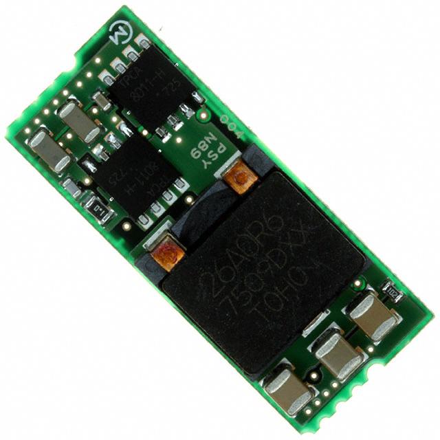
2. Appearance, Dimensions
13.5 ± 0.2
33.0 ±0.2
8.0 max.
(After mount)
Top
View
P1
8.78 ± 0.2
P1
P2
P2
P1
P1
P2
Pin detail
7.83±0.2
1.29± 0.2
5 6
9 10 11 12
1.20
1.50
P
1
+0.20
1.60 -0.10
Bottom View
1.29 ± 0.2
1 2
1.24 ± 0.2
P1=1.90 mm
P2=2.93 mm
P1
13
14
0.97±0.2
0.90 ± 0.2
7 8
(1.45)
Hatching area: Lead Free Solder
(user soldering portion)
Marking
(1)
Pin No.1 Marking
(2)
Parts No.
/
MFG ID
PSY
(3)
Lot No.
□□□
①②③
①Production Factory
②Production Year
③Production Month(1,2,3,…9,O,N,D)
Note:
1. This datasheet is downloaded from the website of Murata Manufacturing co., ltd. Therefore, it’ s specifications are subject to change or our
products in it may be discontinued without advance notice. Please check with our sales representatives or product engineers before ordering.
2. This datasheet has only typical specifications because there is no space for detailed specifications. Therefore, please approve our product
specifications or transact the approval sheet for product specifications before ordering.
2010.11.24
�MPDTY402S DATA Sheet
2
Pin Number and Function
Pin No.
Symbol
Function
1,2
Vin
Input Voltage
5,6
GND
GND
7,8
Vout
Output Voltage
9,10
TRIM
Output Voltage Adjustment
11,12
Sense
Output Voltage Sense
13,14
ON/OFF
Remote ON/OFF
3. Block Diagram
Vout
Vin
7,8
1,2
SENSE
11,12
5,6
GND
13,14
9,10
Control Circuit
ON/OFF
4. Environmental Conditions
4.1 Operating Temperature Range
4.2 Storage Temperature Range
4.3 Operating Humidity Range
4.4 Storage Humidity Range
TRIM
-40°C ~ +85°C
-40°C ~ +85°C
20% ~ 85% (No water condenses in any cases.)
10% ~ 90% (No water condenses in any cases.)
5. Absolute Maximum Rating
Item
Maximum Input Voltage
ON/OFF Pin Voltage
Unit
V
V
Absolute Rating
6.3
-0.3~Vin+0.3
Remarks
No voltage, no matter how instantaneous, shall be applied beyond the absolute maximum voltage rating to this
product. If you apply any voltage over this limit the product characteristics will deteriorate or the product itself will
be destroyed. Even though it may continue operating for a while after the over-voltage event, its life will likely be
shortened significantly. Reliability and life of the module may degrade similarly if the maximum operating voltage
rating is continuously exceeded. This product is designed to operate within the maximum operating voltage rating
specification.
Note:
1. This datasheet is downloaded from the website of Murata Manufacturing co., ltd. Therefore, it’ s specifications are subject to change or our
products in it may be discontinued without advance notice. Please check with our sales representatives or product engineers before ordering.
2. This datasheet has only typical specifications because there is no space for detailed specifications. Therefore, please approve our product
specifications or transact the approval sheet for product specifications before ordering.
2010.11.24
�MPDTY402S DATA Sheet
3
6. Characteristics
o
6. 1 Electrical Characteristics (Ta=25 C)
Value
Item
Condition
Symbol
Input Voltage Range
Vin
Rising UVLO Threshold
UVLOr
Vin increasing
Falling UVLO Threshold
UVLOf
Vin decreasing
Output Voltage
Adjustable Range
Vout
Output Voltage Tolerance
Vo tol
Output Current
Iout
Ripple Voltage
Vrpl
Efficiency
EFF
Operating Frequency
Frq
Over Vin, Io, temperature range
Rset=0.5% tolerance
See the thermal derating curve
in section 6.2.
Vin =5V, Iout=16A, BW=20MHz,
Cout=10μF
Vin =5V, Vout=3.3V, Iout=16A
If ON/OFF pin is connected
to Vin or left open, the
ON
DC-DC converter shall be
“ON”.
If ON/OFF pin is connected
to
GND,
the
DC-DC OFF
Converter shall be “OFF”.
If output is shorted to GND , DC-DC
converter shall be operated in a hiccup
mode. After the short circuit event has
cleared, the output is automatically
brought back into regulation.
ON/OFF pin High Voltage
VIH
ON/OFF pin Low Voltage
VIL
Short Circuit Protection
SCP
Over Temperature Protection
OTP
Reset, followed by auto-recovery
External Output Capacitor
Cout
When input voltage is ideal voltage
source
Output Rise Time
Tr
Rising Overshoot
Vover
Output Delay
Td
Vo=10%~90%
Vin High :ON/OFF Low→High
Vo=10%
Unit
Min.
Typ.
Max.
3.0
-
5.5
V
-
2.05
-
V
1.9
V
0.7525
-
3.63
V
-3.0
-
+3.0
%V
0
-
16
A
-
25
50
mV(pp)
-
95
-
%
-
300
-
kHz
Vin-0.3
-
Vin
V
0
-
0.3
V
16.5
35
-
A
10
-
1000
μF
-
4
-
msec
-
-
+3
%
-
4
-
msec
Note:
1. This datasheet is downloaded from the website of Murata Manufacturing co., ltd. Therefore, it’ s specifications are subject to change or our
products in it may be discontinued without advance notice. Please check with our sales representatives or product engineers before ordering.
2. This datasheet has only typical specifications because there is no space for detailed specifications. Therefore, please approve our product
specifications or transact the approval sheet for product specifications before ordering.
2010.11.24
�MPDTY402S DATA Sheet
4
6. 2 Thermal Derating
Output Current [ A ]
MPDTY402S Thermal Derating
18
16
14
12
10
8
6
4
2
0
20
30
40
50
60
70
80
90
Ta[deg.C.]
0m/s
1m/s
The above derating limits apply to this product soldered directly to 101.6*101.6mm*1.6mm PCB. Any
adjacent parts of high temperature may cause overheating. For reliable operation, please ensure that the
FET temperature of this product is maintained below 120°C and the inductor temperature is below 106°C.
Note:
1. This datasheet is downloaded from the website of Murata Manufacturing co., ltd. Therefore, it’ s specifications are subject to change or our
products in it may be discontinued without advance notice. Please check with our sales representatives or product engineers before ordering.
2. This datasheet has only typical specifications because there is no space for detailed specifications. Therefore, please approve our product
specifications or transact the approval sheet for product specifications before ordering.
2010.11.24
�MPDTY402S DATA Sheet
5
7. Operation information
7.1. Adjusting the Output Voltage
The output voltage can be adjusted from 0.7525V to 3.63V by connecting resistors between TRIM-pin(9,10Pin)
to GND(5,6)-pin.
The following equation gives the required external-resistor values to adjust the output voltage to the required
Vout.
MPDTY402S
Vout
Internal Circuit
30kΩ
5.1kΩ
TRIM pin
21070
Rtrim
Error amp
400kΩ
-5110
Rtrim=
[Ω]
Vout[V]-0.7525[V]
Vout[V]
3.3
Calculated Rtrim[Ω]
3160
Rtrim example [Ω]
3.0k+160
2.5
1.8
6947
15004
6.8k+150
15k+3.9
1.5
23077
22k+1.1k
1.2
0.7525
41973
Open
39k+3k
Open
7.2. ON/OFF Control
ON/OFF function
Using the ON/OFF feature, the operation of this product can be disabled without removal of the input voltage.
Sequencing of a power supply system and power-saving control can be easily achieved using this function.
ON/OFF Control Operation
When ON/OFF-pin(11,12pin)are left open
When ON/OFF-pin(11,12pin)are connected to GND
…… Output Voltage =ON
…… Output Voltage =OFF
MPDTY402S
13,14
3,4
example
GND
on/off
or
Note:
1. This datasheet is downloaded from the website of Murata Manufacturing co., ltd. Therefore, it’ s specifications are subject to change or our
products in it may be discontinued without advance notice. Please check with our sales representatives or product engineers before ordering.
2. This datasheet has only typical specifications because there is no space for detailed specifications. Therefore, please approve our product
specifications or transact the approval sheet for product specifications before ordering.
2010.11.24
�MPDTY402S DATA Sheet
6
7.3. Output Voltage Sensing
By connecting SENSE-pin to the load, output voltage drop in wiring shall be compensated.
Vout
MPDTY402S
SENSE
Load
GND
Please do NOT connect SENSE-pin to the output of LC filter that is set to the Vout line.
When using this way, this product will not operate properly.
Vout
MPDTY402S
SENSE
Load
GND
7.4. Input External capacitor
It is recommended to connect a low-impedance electrolytic capacitor of 100μF or more at Vin terminal.
Smaller input capacitor may leads to an unstable operation of this product caused by input voltage
fluctuation. Please check the proper operation of it on your product when smaller input capacitor is used.
Using ceramic capacitors as input capacitor may cause an increase of output voltage, because input ripple
current flows through the external input capacitor and wiring resistance.
This phenomenon is affected by the position of external capacitors, the value of external capacitors and
voltage difference between Vin and Vout. Using low-impedance electrolytic capacitor will ease this problem.
Please check the proper operation of it on your product when ceramic input capacitor is used.
MPDTY402S
Vin
Cin
Vout
Ripple current
Rw×Irpl appears as additional
output ripple voltage.
Rw
Wiring resistance
7.5. Output External capacitor
Ceramic capacitors are recommended as output external capacitor.
Using ceramic capacitors, small output variation and small ripple voltage are realized.
Output capacitor should be within 10μF to 1000μF. Output capacitor shall be placed near the
output terminal. When using plural capacitors, please make sure to place a capacitor of at least
47μF near the output terminal, and place other capacitors near the load.
When using LC output filter, please make sure to place a capacitor of at least 10μF near the output
terminal.
Note:
1. This datasheet is downloaded from the website of Murata Manufacturing co., ltd. Therefore, it’ s specifications are subject to change or our
products in it may be discontinued without advance notice. Please check with our sales representatives or product engineers before ordering.
2. This datasheet has only typical specifications because there is no space for detailed specifications. Therefore, please approve our product
specifications or transact the approval sheet for product specifications before ordering.
2010.11.24
�MPDTY402S DATA Sheet
7
8. Reliability
8.1. Humidity
According to JIS-C-0022.
40土2°C, 90 to 95%RH, 100 hours. Leave for 4 hours at room temperature.
No damage in appearance and no deviation from electrical characteristics (section 6.1.).
8.2. Temperature Cycles
Repeat cycle 5 times. Leave 2 hours at room temp.
No damage in appearance and no deviation from electrical characteristics (section 6.1.)..
Step
Condition
Time
1
-40°C±3°C
30 minutes
2
Room Temp.
5-10 minutes
3
+85°C±2°C
30 minutes
4
Room Temp.
5-10 minutes
8.3. Vibration
10 to 55Hz, 1.5mm amplitude (1minute cycle), 1 hour for each of X, Y, Z directions.
No damage in appearance and no deviation from electrical characteristics (section 6.1.).
8.4. Mechanical Shock
20G, 1 time for each X, Y, Z directions.
No damage in appearance and no deviation from electrical characteristics (section 6.1.).
9. Test Circuit
In the following test circuit, the initial values under item 6.1. should be met.
9.1. General Measure Circuit
Vout
7,8
1,2
SENSE
Vin
Open=ON
Short=OFF
ON/OFF
Cin: 100µF
MPDTY402S
11,12
RL
TRIM
Cout: 10µF
9,10
13,14
5,6
Rset
GND
GND
Cin :100F/10V
Ceramic Capacitor
Cout:10F/6.3V
Ceramic Capacitor
Please make sure to place Cin and Cout nearby input and output terminal of DC-DC converter.
Note:
1. This datasheet is downloaded from the website of Murata Manufacturing co., ltd. Therefore, it’ s specifications are subject to change or our
products in it may be discontinued without advance notice. Please check with our sales representatives or product engineers before ordering.
2. This datasheet has only typical specifications because there is no space for detailed specifications. Therefore, please approve our product
specifications or transact the approval sheet for product specifications before ordering.
2010.11.24
�MPDTY402S DATA Sheet
8
9.2. Ripple Noise Measurement Circuit
Coaxial cable :1.5D-2V, L=1.5m
Oscilloscope
BW:20MHz
Vout
DC-DC Converter
GND
Terminator
(Keisokugiken TRC-50F)
Ceramic Capacitor
Equivalent circuit
R:50
C:0.01F
A: Ripple Noise Voltage
B: Ripple Voltage
B
A
C: Switching Period
C
Note:
1. This datasheet is downloaded from the website of Murata Manufacturing co., ltd. Therefore, it’ s specifications are subject to change or our
products in it may be discontinued without advance notice. Please check with our sales representatives or product engineers before ordering.
2. This datasheet has only typical specifications because there is no space for detailed specifications. Therefore, please approve our product
specifications or transact the approval sheet for product specifications before ordering.
2010.11.24
�MPDTY402S DATA Sheet
9
10. Packaging Specification
10.1. Emboss Tape Dimensions
φ 1.5
24.0
8.1
1.75
0.4
5°
4.0
33.4
44.0
40.4
20.2
2.0
φ 2.0
1.5
1.7
0.2
Pulling direction
10.2. Real Dimensions
49.4±1.0
45.4±1.0
φ 100±1
φ 330±2
A
2.0±0.5
Indication
φ 21.0±0.8
φ 13.0±0.5
Portion A
Note:
1. This datasheet is downloaded from the website of Murata Manufacturing co., ltd. Therefore, it’ s specifications are subject to change or our
products in it may be discontinued without advance notice. Please check with our sales representatives or product engineers before ordering.
2. This datasheet has only typical specifications because there is no space for detailed specifications. Therefore, please approve our product
specifications or transact the approval sheet for product specifications before ordering.
2010.11.24
�MPDTY402S DATA Sheet
10
10.3. Taping Specification
Epmty portion
(400mm MIN)
Epmty portion
(200mm MIN)
Leader portion
(200mm MIN)
"Module on tape" portion
Indication
1pin
引き出し方向
Pull direction
モジュールはコイル面を上側、端子面を下側に配置します。
The module is oriented with coil on top and pins on the bottom sides.
10.4. Note
1. The adhesive strength of the protective tape must be within 0.1-1.3N.
(In accordance with JIS 0806-3)
2. Each reel contains 200pcs.
3.The deficiency per reel is 0 piece.
4. The reel shows customer part number, Murata part number and quantity.
5. The color of reel is not designated.
11. Production factory
Komatsu Murata Mfg.Co., Ltd.
Kanazu Murata Mfg. Co., Ltd.
Wakura Murata Mfg. Co., Ltd.
Note:
1. This datasheet is downloaded from the website of Murata Manufacturing co., ltd. Therefore, it’ s specifications are subject to change or our
products in it may be discontinued without advance notice. Please check with our sales representatives or product engineers before ordering.
2. This datasheet has only typical specifications because there is no space for detailed specifications. Therefore, please approve our product
specifications or transact the approval sheet for product specifications before ordering.
2010.11.24
�MPDTY402S DATA Sheet
11
12. Typical Characteristics Data
12.1. Vout=0.7525V
Output
Voltage
静的対負荷変動
0.7751
Vo1 [V]
0.7676
Vin=3V
Vin=3.3V
Vin=3.6V
Vin=4.5V
Vin=5V
Vin=5.5V
0.7600
0.7525
0.7450
0.7375
0.7299
0
2
4
6
8
10
Io [A]
12
14
16
Fig.12-1-1. Output Voltage v.s. Output Current
Efficiency
変換効率
100
Eff [%]
95
Ta=25℃ Vin=3V
Ta=25℃ Vin=3.3V
Ta=25℃ Vin=3.6V
Ta=25℃ Vin=4.5V
Ta=25℃ Vin=5V
Ta=25℃ Vin=5.5V
90
85
80
75
0
2
4
6
8
10
Io [A]
12
14
16
Fig.12-1-2. Efficiency v. s. Output Current
Ripple
Voltage
出力リップルノイズ
50
Vr1 [mVp-p]
40
Vin=3V
Vin=3.3V
Vin=3.6V
Vin=4.5V
Vin=5V
Vin=5.5V
30
20
10
0
0
2
4
6
8
Io [A]
10
12
14
16
Fig.12-1-3. Ripple Voltage v. s. Output Current
Note:
1. This datasheet is downloaded from the website of Murata Manufacturing co., ltd. Therefore, it’ s specifications are subject to change or our
products in it may be discontinued without advance notice. Please check with our sales representatives or product engineers before ordering.
2. This datasheet has only typical specifications because there is no space for detailed specifications. Therefore, please approve our product
specifications or transact the approval sheet for product specifications before ordering.
2010.11.24
�MPDTY402S DATA Sheet
12
12.2. Vout=1.2V
Output
Voltage
静的対負荷変動
1.236
Vo1 [V]
1.224
Vin=3V
Vin=3.3V
Vin=3.6V
Vin=4.5V
Vin=5V
Vin=5.5V
1.212
1.200
1.188
1.176
1.164
0
2
4
6
8
Io [A]
10
12
14
16
Fig.12-2-1. Output Voltage v.s. Output Current
Efficiency
変換効率
100
95
Ta=25℃ Vin=3V
Ta=25℃ Vin=3.3V
Ta=25℃ Vin=3.6V
Ta=25℃ Vin=4.5V
Ta=25℃ Vin=5V
Ta=25℃ Vin=5.5V
Eff [%]
90
85
80
75
0
2
4
6
8
10
Io [A]
12
14
16
Fig.12-2-2. Efficiency v. s. Output Current
Ripple
Voltage
出力リップルノイズ
50
Vr1 [mVp-p]
40
Vin=3V
Vin=3.3V
Vin=3.6V
Vin=4.5V
Vin=5V
Vin=5.5V
30
20
10
0
0
2
4
6
8
Io [A]
10
12
14
16
Fig.12-2-3. Ripple Voltage v. s. Output Current
Note:
1. This datasheet is downloaded from the website of Murata Manufacturing co., ltd. Therefore, it’ s specifications are subject to change or our
products in it may be discontinued without advance notice. Please check with our sales representatives or product engineers before ordering.
2. This datasheet has only typical specifications because there is no space for detailed specifications. Therefore, please approve our product
specifications or transact the approval sheet for product specifications before ordering.
2010.11.24
�MPDTY402S DATA Sheet
13
12.3. Vout=2.5V
Output
Voltage
静的対負荷変動
2.575
Vo1 [V]
2.550
Vin=3V
Vin=3.3V
Vin=3.6V
Vin=4.5V
Vin=5V
Vin=5.5V
2.525
2.500
2.475
2.450
2.425
0
2
4
6
8
Io [A]
10
12
14
16
Fig.12-3-1. Output Voltage v.s. Output Current
Efficiency
変換効率
100
95
Ta=25℃ Vin=3V
Ta=25℃ Vin=3.3V
Ta=25℃ Vin=3.6V
Ta=25℃ Vin=4.5V
Ta=25℃ Vin=5V
Ta=25℃ Vin=5.5V
Eff [%]
90
85
80
75
0
2
4
6
8
10
Io [A]
12
14
16
Fig.12-3-2. Efficiency v. s. Output Current
Ripple
Voltage
出力リップルノイズ
50
Vr1 [mVp-p]
40
Vin=3V
Vin=3.3V
Vin=3.6V
Vin=4.5V
Vin=5V
Vin=5.5V
30
20
10
0
0
2
4
6
8
Io [A]
10
12
14
16
Fig.12-3-3. Ripple Voltage v. s. Output Current
Note:
1. This datasheet is downloaded from the website of Murata Manufacturing co., ltd. Therefore, it’ s specifications are subject to change or our
products in it may be discontinued without advance notice. Please check with our sales representatives or product engineers before ordering.
2. This datasheet has only typical specifications because there is no space for detailed specifications. Therefore, please approve our product
specifications or transact the approval sheet for product specifications before ordering.
2010.11.24
�MPDTY402S DATA Sheet
14
12.4. Vout=3.3V
Output
Voltage
静的対負荷変動
3.399
Vo1 [V]
3.366
3.333
Vin=4.5V
Vin=5V
Vin=5.5V
3.300
3.267
3.234
3.201
0
2
4
6
8
Io [A]
10
12
14
16
Fig.12-4-1. Output Voltage v.s. Output Current
変換効率
Efficiency
100
Eff [%]
95
90
Ta=25℃ Vin=4.5V
Ta=25℃ Vin=5V
Ta=25℃ Vin=5.5V
85
80
75
0
2
4
6
8
10
Io [A]
12
14
16
Fig.12-4-2. Efficiency v. s. Output Current
Ripple
Voltage
出力リップルノイズ
50
Vr1 [mVp-p]
40
30
Vin=4.5V
Vin=5V
Vin=5.5V
20
10
0
0
2
4
6
8
Io [A]
10
12
14
16
Fig.12-4-3. Ripple Voltage v. s. Output Current
Note:
1. This datasheet is downloaded from the website of Murata Manufacturing co., ltd. Therefore, it’ s specifications are subject to change or our
products in it may be discontinued without advance notice. Please check with our sales representatives or product engineers before ordering.
2. This datasheet has only typical specifications because there is no space for detailed specifications. Therefore, please approve our product
specifications or transact the approval sheet for product specifications before ordering.
2010.11.24
�MPDTY402S DATA Sheet
15
13. Mounting Condition
13.1. PCB Land Pattern Recommendation
7.54
4.83
4.83
4.83
7.87
Recommended land size
10.3
4mm × 2.5mm
10.9
0.635
Unit: mm
29.9
There are wiring coppers or through-hole via at the bottom side of the DC-DC converter.
When you design your PCBs, please be careful not to short the circuit of the DC-DC converter or PCBs.
13.2. Recommended Soldering Conditions
Reflow Soldering
This product is RoHS compliant. The following profile is recommended for the reflow of this
product using Pb-free solder paste (Sn-Ag-Cu).
Method
:
Full convection reflow soldering
Reflow Soldering Profile
JEDEC IPC/JEDEC J-STD-020D
Table 5-2 Classification Reflow Profile
Pb-Free Assembly Large Body
Profile details
Soldering temperature
Soldering time
Heating time
Preheating time
Programming rate
Descending rate
Total soldering time
Times
:
:
:
:
:
:
:
:
245ºC+0/-5ºC
30 seconds, 240 to 245ºC
60 to 150 seconds, over217ºC
60 to 120 seconds,150 to 200ºC
3ºC/ sec. Max., 217 to 245ºC
6ºC/ sec. Max.
8 minutes Max., 25 to 245ºC
1 time
2 4 5o C
217 oC
Parts surface temperature [ºC]
200 oC
60~150
(seconds)
1 5 0 oC
60~120 (seconds)
Times
※Do not vibrate for the products on reflow.
Please need to take care temperature control because mounted parts may come off if the product are left
under the high temperature.
Do not reflow DC-DC converter as follows, because DC-DC converter may fall down from a substrate during
Substrate
reflowing.
Note:
DC-DC Converter
1. This datasheet is downloaded from the website of Murata Manufacturing co., ltd. Therefore, it’ s specifications are subject to change or our
products in it may be discontinued without advance notice. Please check with our sales representatives or product engineers before ordering.
2. This datasheet has only typical specifications because there is no space for detailed specifications. Therefore, please approve our product
specifications or transact the approval sheet for product specifications before ordering.
2010.11.24
�MPDTY402S DATA Sheet
16
14. Notice
14. 1.
Both input-side and output side, please make the wiring loop between plus and minus as small as possible.
The influence of a leakage inductance can be reduced.
14. 2. Please make the power line pattern as wide and short as possible.
The Following figure is an example of recommendable PCB design.
Vout
Output Capacitor
GND
Input capacitor
Vin
14. 3.
This product should not be operated in parallel or in series.
14. 4.
Please do not use a connector or a socket to connect this product to your product.
The electric characteristics may be deteriorated by the influence of contact resistance.
14. 5.
Be sure to provide an appropriate fail-safe function on your product to prevent secondary damage
that may be caused due to abnormal functional or failure of this product.
14. 6.
14. 7.
Inrush current protection is not a feature of this product.
Be sure not to warp your PCB over 90μm.
If not, the parts on the backside of this device touch on your PCB, and that may lead to cracks of the
backside parts or reliability deterioration of this device.
Note:
1. This datasheet is downloaded from the website of Murata Manufacturing co., ltd. Therefore, it’ s specifications are subject to change or our
products in it may be discontinued without advance notice. Please check with our sales representatives or product engineers before ordering.
2. This datasheet has only typical specifications because there is no space for detailed specifications. Therefore, please approve our product
specifications or transact the approval sheet for product specifications before ordering.
2010.11.24
�MPDTY402S DATA Sheet
17
14. 8.
Please connect the input terminals with the correct polarity. If an error in polarity connection is made this
product may be damaged. If this product is damaged internally, an elevated input current may flow, and so
this product may exhibit an abnormal temperature rise, or your product may be damaged.
Please add a diode and fuse per the following diagram to protect them.
fuse
+
+
+
diode
IN
OUT
-
Load
-
※Please select diode and fuse after confirming the operation of your product.
14. 9. Cleaning
Please use no-cleaning type flux and do not wash this product.
14.10. Storage
14.10.1. Please store the products in room where the temperature/humidity is stable and direct sunlight cannot
come in, and use the products within 6 months after delivery.
Please avoid damp and heat or such places where the temperature greatly changes, as water may
condense on this product, and the quality of characteristics may be reduced, and/or be the solderability
may be degraded.
If this product needs to be stored for a long time (more than 1 year), this product may be degraded in
solderability and/or corroded. Please test the solderability of this product regularly.
Baking before reflow process is unnecessary to store the products under 30℃,60%RH or less up to 6
months.
In case the storage condition is over above mentioned, if these are unpacked condition, please bake them
at 125℃±5℃/24hour. If these are packed in a tape, please bake them before soldering at 60℃±5℃
/168hour.
14.10.2. Please do not store this product in places such as :
A dusty place, a place exposed directly to sea breeze, or in an atmosphere containing corrosive gas
(Cl2,NH3,SO2,NOX and so on).
Note:
1. This datasheet is downloaded from the website of Murata Manufacturing co., ltd. Therefore, it’ s specifications are subject to change or our
products in it may be discontinued without advance notice. Please check with our sales representatives or product engineers before ordering.
2. This datasheet has only typical specifications because there is no space for detailed specifications. Therefore, please approve our product
specifications or transact the approval sheet for product specifications before ordering.
2010.11.24
�MPDTY402S DATA Sheet
18
14. 11 Operational Environment and Operational Conditions
14. 11. 1. Operational Environment
This product is not water-, chemical- or corrosion-proof.
In order to prevent leakage of electricity and abnormal temperature rise of the product, do not operate
under the following environmental conditions:
(1) An atmosphere containing corrosive gas (Cl2, NH3, SO2, NOX and so on)
(2) A high-dust environment
(3) Under the exposure of direct sunlight
(4) A location where the likelihood of exposure to water or water condensation exists.
(5) A location exposed to ocean air
(6) Any locations similar to the above
14. 11. 2. Operational Conditions
Please use this product within specified values (power supply, temperature, input, output and load
condition, and so on). If the product is exposed to conditions outside of the specified values reliability of
the product may be adversely effected.
14. 11. 3. Note prior to use
Diminished reliability and/ or failure may result if the product is exposed to a high-level static charge,
over-rated voltage or reverse voltage. Please avoid the following conditions be avoided prior to use of
the product:
(1) Supply of power outside of rated values (see section 8)
(2) Supply of reverse power or inadequate connection of a 0 V(DC)line
(3) Electrostatic discharge from production line and/ or operator
(4) Electrification of the product from electrostatic induction
(5) Excessive mechanical shock
14. 12. Transportation
Murata recommends that when transporting this product, it be packed so as to avoid damage by
mechanical
vibration or exposure to adverse conditions such as ocean air, high humidity. It is additionally
recommended
that appropriate instructions and guidelines be communicated to carriers to prevent exposure to these
same conditions.
!
Note
1. Murata recommends that customers ensure that the evaluation and testing of these devices are completed
withthis product actually assembled on their product.
2. Please contact our main sales office or nearby sales office before using our products for the applications
listed below which require especially high reliability for the prevention of defects which might directly
cause damage to the third party’s life, body or property or this products for any other applications that
described in the above.
①Aircraft equipment
②Aerospace equipment
③Undersea equipment
④Power plant control equipment
⑤Medical equipment
⑥Transportation equipment (vehicles, trains, ships, etc.)
⑦Traffic signal equipment
⑧Disaster prevention /crime prevention equipment
⑨Data-processing equipment
⑩Application of similar complexity and/or reliability requirements to the applications listed in the above.
3. This DATA Sheet is indicated in March 2009. About the written contents, since changing without a
preliminary announcement for improvement and supply are sometimes stopped, please confirm in case of
ordering.
If written contents are unknown, please ask to our main sales office or nearby sales office.
Note:
1. This datasheet is downloaded from the website of Murata Manufacturing co., ltd. Therefore, it’ s specifications are subject to change or our
products in it may be discontinued without advance notice. Please check with our sales representatives or product engineers before ordering.
2. This datasheet has only typical specifications because there is no space for detailed specifications. Therefore, please approve our product
specifications or transact the approval sheet for product specifications before ordering.
2010.11.24
�


 工商网监
湘ICP备2023018690号
工商网监
湘ICP备2023018690号
