NTC Thermistors
�!Note • Please read rating and !CAUTION (for storage, operating, rating, soldering, mounting and handling) in this catalog to prevent smoking and/or burning, etc.
• This catalog has only typical specifications. Therefore, please approve our product specifications or transact the approval sheet for product specifications before ordering.
EU RoHS Compliant
s!LLTHEPRODUCTSINTHISCATALOGCOMPLYWITH%52O(3�
s%52O(3IS�THE%UROPEAN$IRECTIVE��������%5ONTHE2ESTRICTIONOFTHE5SE
OF#ERTAIN(AZARDOUS3UBSTANCESIN%LECTRICALAND%LECTRONIC%QUIPMENT��
sForMOREDETAILS�PLEASEREFErToOurWEBSITE'MurATAgSAPProAcHFoR%52O(3'
�HTTP���WWW�MURATA�COM�INFO�ROHS�HTML �
�!Note • Please read rating and !CAUTION (for storage, operating, rating, soldering, mounting and handling) in this catalog to prevent smoking and/or burning, etc.
• This catalog has only typical specifications. Therefore, please approve our product specifications or transact the approval sheet for product specifications before ordering.
1
Contents
Product specifications are as of
Part Numbering
p2
Basic Characteristics
p6
Temperature Sensor and Compensation
0201 (0603) Size
p7
Temperature Sensor and Compensation
0402 (1005) Size
p8
Temperature Sensor and Compensation
0603 (1608) Size
p10
Temperature Sensor and Compensation
0805 (2012) Size
p12
December 2014.
1
2
3
4
5
Temperature Sensor and Compensation Chip Type
Standard Land Pattern Dimensions
p13
Temperature Sensor and Compensation Chip Type
Temperature Characteristics (Center Value)
p14
Temperature Sensor and Compensation Chip Type
!Caution/Notice
p18
Temperature Sensor and Compensation Chip Type
Package
p22
Temperature Sensor Thermo String Type
Temperature Sensor Thermo String Type
Specifications and Test Methods
6
Temperature Sensor Lead Type
Temperature Sensor Lead Type
Specifications and Test Methods
7
8
2
Temperature Sensor Lead Insulation Type
(Radial Type)
p25
4
5
p26
p28
p29
6
p30
Temperature Sensor Lead Insulation Type
(Radial Type) Specifications and Test Methods
p31
Temperature Sensor Thermo String/Lead Type
Temperature Characteristics (Center Value)
p32
Temperature Sensor Thermo String/Lead Type
!Caution/Notice
p33
Temperature Sensor Thermo String/Lead Type
Package
p35
Inrush Current Suppression Lead Type
3
p36
Current - R Ratio (RT/R25)/
Current - Temperature Characteristics (Typical)
p38
Inrush Current Suppression Lead Type
!Caution/Notice
p42
Inrush Current Suppression Lead Type
Package
p44
Please check the MURATA home page (http://www.murata.com/)
if you cannot find the part number in the catalog.
7
8
�!Note • Please read rating and !CAUTION (for storage, operating, rating, soldering, mounting and handling) in this catalog to prevent smoking and/or burning, etc.
• This catalog has only typical specifications. Therefore, please approve our product specifications or transact the approval sheet for product specifications before ordering.
o Part Numbering
NTC Thermistors for Temp. Sensor and Compensation Chip Type
(Part Number)
NC
P
18
XH
103
q
w e
r
t
03
RB
y u
i
J
qProduct ID
tResistance
Product ID
NC
NTC Thermistors Chip Type
wSeries
Expressed by three-digit alphanumerics. The unit is ohm (Ω).
The first and second figures are significant digits, and the third
figure expresses the number of zeros that follow the two figures.
Ex.
Code
Resistance
Code
Series
102
1kΩ
P
Plated Termination Series
103
10kΩ
104
100kΩ
eDimensions (LgW)
yResistance Tolerance
Code
Dimensions (LgW)
EIA
03
0.60g0.30mm
0201
Code
Resistance Tolerance
15
1.00g0.50mm
0402
D
±0.5%
18
1.60g0.80mm
0603
F
±1%
21
2.00g1.25mm
0805
E
±3%
J
±5%
rTemperature Characteristics
2
uIndividual Specifications
Code
Temperature Characteristics
XC
Nominal B-Constant 3100e3149K
Structures and other specifications are expressed by two figures.
XF
Nominal B-Constant 3250e3299K
Ex.
XH
Nominal B-Constant 3350e3399K
XM
Nominal B-Constant 3500e3549K
XQ
Nominal B-Constant 3650e3699K
Code
Individual Specifications
03
Standard Type
iPackaging
XV
Nominal B-Constant 3900e3949K
Code
Packaging
XW
Nominal B-Constant 3950e3999K
RA
Plastic Taping 4mm Pitch (4000 pcs.)
WB
Nominal B-Constant 4050e4099K
RB
Paper Taping 4mm Pitch (4000 pcs.)
WD
Nominal B-Constant 4150e4199K
RC
Paper Taping 2mm Pitch (10000 pcs.)
WF
Nominal B-Constant 4250e4299K
RL
Paper Taping 2mm Pitch (15000 pcs.)
WL
Nominal B-Constant 4450e4499K
WM
Nominal B-Constant 4500e4549K
�!Note • Please read rating and !CAUTION (for storage, operating, rating, soldering, mounting and handling) in this catalog to prevent smoking and/or burning, etc.
• This catalog has only typical specifications. Therefore, please approve our product specifications or transact the approval sheet for product specifications before ordering.
NTC Thermistor for Temperature Sensor Thermo String Type
(Part Number)
NXF
T
15
XH
103
q
w
e
r
t
F
A
2
B
y u i o
qProduct ID
025
!0
uLead Wire Type
Product ID
NXF
NTC Thermistors Sensor Thermo String Type
Code
Lead Wire Type
A
ø0.3mm Copper Lead Wire
with Polyurethane Coat
wIndividual Specifications
Code
Individual Specifications
T
Commercial Type
iShape of the Lead Wire Kink
eChip Dimensions
Code
Dimensions (LxT)
EIA
15
1.00 x 0.50mm
0402
rTemperature Characteristics
Code
Temperature Characteristics
XH
Nominal B-Constant 3350–3399K
Code
Shape of the Lead Wire Kink
1
Twisted Lead Wire Type
2
Standard Type
oPackaging
Code
Packaging
B
Bulk
!0Dimensions (Full Length)
XV
Nominal B-Constant 3900–3949K
Code
Dimensions (Full Length)
WB
Nominal B-Constant 4050–4099K
025
25mm
WF
Nominal B-Constant 4250–4299K
030
30mm
040
40mm
050
50mm
060
60mm
070
70mm
080
80mm
tResistance
Expressed by three figures. The unit is (Ω). The first and second
figures are significant digits, and the third figure expresses the
number of zeros that follow the two figures.
Ex.
Code
Resistance
103
10kΩ
104
100kΩ
yResistance Tolerance
Code
Resistance Tolerance
F
±1%
090
90mm
100
100mm
110
110mm
120
120mm
130
130mm
140
140mm
150
150mm
3
�!Note • Please read rating and !CAUTION (for storage, operating, rating, soldering, mounting and handling) in this catalog to prevent smoking and/or burning, etc.
• This catalog has only typical specifications. Therefore, please approve our product specifications or transact the approval sheet for product specifications before ordering.
NTC Thermistor for Temperature Sensor/Lead Type
(Part Number)
NXR
T
15
XH
103
q
w
e
r
t
F
A
1
B
y u i o
qProduct ID
040
!0
uLead Wire Type
Product ID
NXR
NTC Thermistor Sensor/Lead Type
Code
Lead Wire Type
A
Lead Type: ø0.4mm Copper-clad Fe Wire, Tinned
Lead Insulation Type: ø0.46mm Cu Wire with Coat
wIndividual Specifications
Code
Individual Specifications
T
Commercial Type
eChip Dimensions
Code
Dimensions (LxT)
15
1.00 x 0.50mm
iShape of the Lead Wire
Code
Shape of the Lead Wire
1
Lead Spacing 2.5mm
3
Lead Spacing 5.0mm
5
Lead Spacing 2.5mm (Insulation Type)
oPackaging
rTemperature Characteristics
Code
Packaging
Code
Temperature Characteristics
A
Ammo Pack Taping
XH
Nominal B-Constant 3350–3399K
B
Bulk
XM
Nominal B-Constant 3500–3549K
XV
Nominal B-Constant 3900–3949K
WB
Nominal B-Constant 4050–4099K
Code
Dimensions (Full Length)
WF
Nominal B-Constant 4250–4299K
010
10mm
tResistance
Expressed by three figures. The unit is (Ω). The first and second
figures are significant digits, and the third figure expresses the
number of zeros that follow the two figures.
Ex.
Code
Resistance
202
2.0kΩ
103
10kΩ
104
100kΩ
yResistance Tolerance
4
Code
Resistance Tolerance
F
±1%
E
±3%
J
±5%
!0Dimensions (Full Length)
020
20mm
025
25mm (Insulation Type only)
030
30mm
035
35mm (Insulation Type only)
040
40mm
045
45mm (Insulation Type only)
016
16mm (Taping Type/Lead distance
between reference and bottom planes)
�!Note • Please read rating and !CAUTION (for storage, operating, rating, soldering, mounting and handling) in this catalog to prevent smoking and/or burning, etc.
• This catalog has only typical specifications. Therefore, please approve our product specifications or transact the approval sheet for product specifications before ordering.
NTC Thermistors for Inrush Current Suppression Lead Type
(Part Number)
NT
PA7
160
L
BM
B0
q
w
e
r
t
y
qProduct ID
rResistance Tolerance
Product ID
NT
NTC Thermistors
wSeries
Code
Resistance Tolerance
L
±15%
tIndividual Specifications
Code
Series
Nominal Body Diameter
The lead structure and other specifications are expressed
by two-digit alphanumerics.
PA5
ø5mm
PA6
ø6mm
Code
Individual Specifications
Body Diameter
PA7
ø7mm
B1
Standard Type (Ammo Pack)
ø7mm, ø9mm
BM
Standard Type (Bulk)
ø7mm, ø9mm
Inrush Current
Suppression
Lead Type
PA9
PAA
ø9mm
Standard Type (Ammo Pack) ø10mm, ø13mm
ø10mm
D6
PAD
ø13mm
DK
Standard (Bulk)
ø18mm, ø22mm
PAJ
ø18mm
DN
Standard (Bulk)
ø10mm, ø13mm
PAN
ø22mm
yPackaging
eResistance
Expressed by three-digit alphanumerics. The unit is ohm (Ω).
The first and second figures are significant digits, and the third
figure expresses the number of zeros that follow the two figures.
If there is a decimal point, it is expressed by the capital letter "R."
In this case, all figures are significant digits.
Ex.
Code
Code
Packaging
A0
Ammo Pack Taping
B0
Bulk
Resistance
3R0
3Ω
100
10Ω
5
�!Note • Please read rating and !CAUTION (for storage, operating, rating, soldering, mounting and handling) in this catalog to prevent smoking and/or burning, etc.
• This catalog has only typical specifications. Therefore, please approve our product specifications or transact the approval sheet for product specifications before ordering.
Basic Characteristics
!Basic Characteristics
2. B-Constant
as (1) formula
B=Rn (R/R0) / (1/T-1/T0)
Resistance vs. Temperature
102
Resistance vs. Temperature Characteristics, R/R25
1. Zero-power Resistance of Thermistor: R
R=R0 expB (1/T-1/T0) ..............(1)
R: Resistance in ambient temperature T (K)
(K: absolute temperature)
R0: Resistance in ambient temperature T0 (K)
B: B-Constant of Thermistor
............(2)
3. Thermal Dissipation Constant
When electric power P (mW) is spent in ambient
temperature T1 and thermistor temperature rises T2,
the formula is as follows
P=C (T2-T1) ..................(3)
C: Thermal dissipation constant (mW/°C)
Thermal dissipation constant is varied with dimensions,
measurement conditions, etc.
4. Thermal Time Constant
Period in which the thermistor's temperature will change
63.2% of its temperature difference from ambient
temperature T0 (°C) to T1 (°C).
101
1
10–1
B=3450
B=3900
B=4100
10–2
–20
0
20 40 60 80 100 120
Temperature (°C)
Thermal Time Constant
T1
Temperature
X
63.2%
T0
Time
!Performance
Item
Resistance
Condition
Measured by zero-power in specified ambient temperature.
Calculated between two specified ambient temperatures by the next formula.
T and T0 is absolute temperature (K).
B-Constant
B=
Thermal Dissipation
Constant
Rn (R/R0)
1/TY1/T0
Shows necessary electric power that Thermistor's temperature rises 1°C by self-heating.
It is calculated by the next formula (mW/°C).
C=
P
TYT0
Rated Electric Power
Shows the required electric power that causes the thermistor's temperature to rise to a specified temperature by
self-heating, at ambient temperature of 25 °C.
Permissible Operating Current
It is possible to keep the thermistor's temperature rising max. 1°C.
Please inquire about test conditions and ratings.
6
�!Note • Please read rating and !CAUTION (for storage, operating, rating, soldering, mounting and handling) in this catalog to prevent smoking and/or burning, etc.
• This catalog has only typical specifications. Therefore, please approve our product specifications or transact the approval sheet for product specifications before ordering.
NTC Thermistors
1
Temperature Sensor and Compensation 0201 (0603) Size
0.30±0.03
Chip NTC Thermistors' Ni barrier termination provides
excellent solderability and their unique construction
offers high stability in the application's environment.
0.15±0.05
c Features
0.15±0.05
0.60±0.03
0.30±0.03
1. Excellent solderability and high stability in the
application's environment
2. Excellent long-term stability
3. High accuracy in resistance and B-Constant
4. Reflow soldering possible
5. NCP series are recognized by UL/cUL.
(UL1434, File No.E137188)
Electrode
(Ag System + Ni Plating + Sn Plating)
(in mm)
c Applications
1. Temperature compensation for transistors, ICs, and
crystal oscillators in mobile communications
2. Temperature sensor for rechargeable batteries
Part Number
Resistance B-Constant
B-Constant
B-Constant
B-Constant
Permissible Operating Rated Electric Typical Dissipation
(25°C)
(25-50°C)
(25-80°C)
(25-85°C)
(25-100°C)
Current (25°C)
Power (25°C)
Constant (25°C)
(ohm)
(K)
(Reference Value) (K) (Reference Value) (K) (Reference Value) (K)
(mA)
(mW)
(mW/°C)
NCP03XM102p05RL
1.0k
3500 ±1%
3539
3545
3560
1.00
100
1
NCP03XM152p05RL
1.5k
3500 ±1%
3539
3545
3560
0.81
100
1
NCP03XM222p05RL
2.2k
3500 ±1%
3539
3545
3560
0.67
100
1
NCP03XM332p05RL
3.3k
3500 ±1%
3539
3545
3560
0.55
100
1
NCP03XM472p05RL
4.7k
3500 ±1%
3539
3545
3560
0.46
100
1
NCP03XH682p05RL
6.8k
3380 ±1%
3428
3434
3455
0.38
100
1
NCP03XH103F05RL
10k ±1%
3380 ±1%
3428
3434
3455
0.31
100
1
NCP03XH103p05RL
10k
3380 ±1%
3428
3434
3455
0.31
100
1
NCP03XV103p05RL
10k
3900 ±1%
3930
3934
3944
0.31
100
1
NCP03XH153p05RL
15k
3380 ±1%
3428
3434
3455
0.25
100
1
NCP03XH223p05RL
22k
3380 ±1%
3428
3434
3455
0.21
100
1
NCP03WF333p05RL
33k
4250 ±1%
4303
4311
4334
0.17
100
1
NCP03WB473p05RL
47k
4050 ±3%
4101
4108
4131
0.14
100
1
NCP03WL473p05RL
47k
4485 ±1%
4537
4543
4557
0.14
100
1
NCP03WF683p05RL
68k
4250 ±1%
4303
4311
4334
0.12
100
1
NCP03WL683p05RL
68k
4485 ±1%
4537
4543
4557
0.12
100
1
NCP03WF104F05RL
100k ±1%
4250 ±1%
4303
4311
4334
0.10
100
1
NCP03WF104p05RL
100k
4250 ±1%
4303
4311
4334
0.10
100
1
NCP03WL104p05RL
100k
4485 ±1%
4537
4543
4557
0.10
100
1
NCP03WL154p05RL
150k
4485 ±1%
4537
4543
4557
0.08
100
1
NCP03WL224p05RL
220k
4485 ±1%
4537
4543
4557
0.06
100
1
p is filled with resistance tolerance codes (E: ±3%, J: ±5%).
Rated Electric Power shows the required electric power that the thermistor's temperature rise to 125°C by self-heating, at ambient temperature of 25 °C.
Operating Temperature Range: -40°C to +125°C
7
�!Note • Please read rating and !CAUTION (for storage, operating, rating, soldering, mounting and handling) in this catalog to prevent smoking and/or burning, etc.
• This catalog has only typical specifications. Therefore, please approve our product specifications or transact the approval sheet for product specifications before ordering.
NTC Thermistors
Temperature Sensor and Compensation 0402 (1005) Size
0.5±0.05
Chip NTC Thermistors' Ni barrier termination provides
excellent solderability and their unique construction
offers high stability in the application's environment.
0.25±0.10
c Features
0.25±0.10
1.0±0.05
1. Excellent solderability and high stability in the
application's environment
2. Excellent long-term stability
3. High accuracy in resistance and B-Constant
4. Reflow soldering possible
5. Same B-constant in the same resistance in the three
sizes (0805 size / 0603 size / 0402 size)
Downsize is easy for design.
6. NCP series are recognized by UL/cUL.
(UL1434, File No.E137188)
0.5±0.05
2
Electrode
(Ag System + Ni Plating + Sn Plating)
(in mm)
c Applications
1. Temperature compensation for transistors, ICs, and
crystal oscillators in mobile communications
2. Temperature sensor for rechargeable batteries
3. Temperature compensation of LCD
4. Temperature compensation in general use of electric
circuits
Part Number
Resistance B-Constant
B-Constant
B-Constant
B-Constant
Permissible Operating Rated Electric Typical Dissipation
(25°C)
(25-50°C)
(25-80°C)
(25-85°C)
(25-100°C)
Current (25°C)
Power (25°C)
Constant (25°C)
(ohm)
(K)
(Reference Value) (K) (Reference Value) (K) (Reference Value) (K)
(mA)
(mW)
(mW/°C)
NCP15XC220p03RC
22
3100 ±3%
3126
3128
3136
6.70
100
1
NCP15XC330p03RC
33
3100 ±3%
3126
3128
3136
5.50
100
1
NCP15XC470p03RC
47
3100 ±3%
3126
3128
3136
4.60
100
1
NCP15XC680p03RC
68
3100 ±3%
3126
3128
3136
3.80
100
1
NCP15XF101p03RC
100
3250 ±3%
3282
3284
3296
3.10
100
1
NCP15XF151p03RC
150
3250 ±3%
3282
3284
3296
2.50
100
1
NCP15XM221p03RC
220
3500 ±3%
3539
3545
3560
2.10
100
1
NCP15XM331p03RC
330
3500 ±3%
3539
3545
3560
1.70
100
1
NCP15XQ471p03RC
470
3650 ±2%
3688
3693
3706
1.40
100
1
NCP15XQ681p03RC
680
3650 ±3%
3688
3693
3706
1.20
100
1
NCP15XQ102p03RC
1.0k
3650 ±2%
3688
3693
3706
1.00
100
1
NCP15XW152p03RC
1.5k
3950 ±3%
3982
3987
3998
0.81
100
1
NCP15XW222p03RC
2.2k
3950 ±3%
3982
3987
3998
0.67
100
1
NCP15XW332p03RC
3.3k
3950 ±3%
3982
3987
3998
0.55
100
1
NCP15XM472p03RC
4.7k
3500 ±2%
3539
3545
3560
0.46
100
1
NCP15XW472p03RC
4.7k
3950 ±3%
3982
3987
3998
0.46
100
1
NCP15XW682p03RC
6.8k
3950 ±3%
3982
3987
3998
0.38
100
1
3428
3434
3455
0.31
100
1
NCP15XH103D03RC
10k ±0.5% 3380 ±0.7%
NCP15XH103F03RC
10k ±1%
3380 ±1%
3428
3434
3455
0.31
100
1
NCP15XH103p03RC
10k
3380 ±1%
3428
3434
3455
0.31
100
1
NCP15XV103p03RC
10k
3900 ±3%
3930
3934
3944
0.31
100
1
NCP15XW153p03RC
15k
3950 ±3%
3982
3987
3998
0.25
100
1
NCP15XW223p03RC
22k
3950 ±3%
3982
3987
3998
0.21
100
1
NCP15WL223p03RC
22k
4485 ±1%
4537
4543
4557
0.21
100
1
NCP15WB333p03RC
33k
4050 ±3%
4101
4108
4131
0.17
100
1
NCP15WL333p03RC
33k
4485 ±1%
4537
4543
4557
0.17
100
1
Continued on the following page.
8
�!Note • Please read rating and !CAUTION (for storage, operating, rating, soldering, mounting and handling) in this catalog to prevent smoking and/or burning, etc.
• This catalog has only typical specifications. Therefore, please approve our product specifications or transact the approval sheet for product specifications before ordering.
Continued from the preceding page.
Part Number
NCP15WB473D03RC
Resistance B-Constant
B-Constant
B-Constant
B-Constant
Permissible Operating Rated Electric Typical Dissipation
(25°C)
(25-50°C)
(25-80°C)
(25-85°C)
(25-100°C)
Current (25°C)
Power (25°C)
Constant (25°C)
(ohm)
(K)
(Reference Value) (K) (Reference Value) (K) (Reference Value) (K)
(mA)
(mW)
(mW/°C)
4101
4108
4131
0.14
100
1
NCP15WB473F03RC
47k ±1%
4050 ±1%
4101
4108
4131
0.14
100
1
NCP15WB473p03RC
47k
4050 ±1%
4101
4108
4131
0.14
100
1
NCP15WL473p03RC
47k
4485 ±1%
4537
4543
4557
0.14
100
1
NCP15WD683p03RC
68k
4150 ±3%
4201
4209
4232
0.12
100
1
NCP15WL683p03RC
68k
4485 ±1%
4537
4543
4557
0.12
100
1
4303
4311
4334
0.10
100
1
NCP15WF104D03RC
47k ±0.5% 4050 ±0.5%
100k ±0.5% 4250 ±0.5%
NCP15WF104F03RC
100k ±1%
4250 ±1%
4303
4311
4334
0.10
100
1
NCP15WF104p03RC
100k
4250 ±1%
4303
4311
4334
0.10
100
1
NCP15WL104p03RC
100k
4485 ±1%
4537
4543
4557
0.10
100
1
NCP15WL154p03RC
150k
4485 ±1%
4537
4543
4557
0.08
100
1
NCP15WM154p03RC
150k
4500 ±3%
4571
4582
4614
0.08
100
1
NCP15WM224p03RC
220k
4500 ±3%
4571
4582
4614
0.06
100
1
NCP15WM474p03RC
470k
4500 ±3%
4571
4582
4614
0.04
100
1
2
p is filled with resistance tolerance codes (E: ±3%, J: ±5%).
Rated Electric Power shows the required electric power that the thermistor's temperature rise to 125°C by self-heating, at ambient temperature of 25 °C.
Operating Temperature Range: -40°C to +125°C
9
�!Note • Please read rating and !CAUTION (for storage, operating, rating, soldering, mounting and handling) in this catalog to prevent smoking and/or burning, etc.
• This catalog has only typical specifications. Therefore, please approve our product specifications or transact the approval sheet for product specifications before ordering.
NTC Thermistors
Temperature Sensor and Compensation 0603 (1608) Size
0.8±0.15
Chip NTC Thermistors' Ni barrier termination provides
excellent solderability and their unique construction
offers high stability in the application's environment.
0.2-0.6
c Features
1. Excellent solderability and high stability in the
application's environment
2. Excellent long-term stability
3. High accuracy in resistance and B-constant
4. Flow / Reflow soldering possible
5. Same B-Constant in the same resistance in the three
sizes (0805 size / 0603 size / 0402 size)
Downsize is easy for design.
6. NCP series are recognized by UL/cUL.
(UL1434, File No.E137188)
0.8±0.15
3
0.2-0.6
1.6±0.15
Electrode
(Ag System + Ni Plating + Sn Plating)
(in mm)
c Applications
1. Temperature compensation for transistors, ICs, and
crystal oscillators in mobile communications
2. Temperature sensor for rechargeable batteries
3. Temperature compensation of LCD
4. Temperature compensation in general use of electric
circuits
Part Number
Resistance B-Constant
B-Constant
B-Constant
B-Constant
Permissible Operating Rated Electric Typical Dissipation
(25°C)
(25-50°C)
(25-80°C)
(25-85°C)
(25-100°C)
Current (25°C)
Power (25°C)
Constant (25°C)
(ohm)
(K)
(Reference Value) (K) (Reference Value) (K) (Reference Value) (K)
(mA)
(mW)
(mW/°C)
NCP18XF101p03RB
100
3250 ±3%
3282
3284
3296
3.10
100
1
NCP18XF151p03RB
150
3250 ±3%
3282
3284
3296
2.50
100
1
NCP18XM221p03RB
220
3500 ±3%
3539
3545
3560
2.10
100
1
NCP18XM331p03RB
330
3500 ±3%
3539
3545
3560
1.70
100
1
NCP18XQ471p03RB
470
3650 ±2%
3688
3693
3706
1.40
100
1
NCP18XQ681p03RB
680
3650 ±3%
3688
3693
3706
1.20
100
1
NCP18XQ102p03RB
1.0k
3650 ±2%
3688
3693
3706
1.00
100
1
NCP18XW152p03RB
1.5k
3950 ±3%
3982
3987
3998
0.81
100
1
NCP18XW222p03RB
2.2k
3950 ±3%
3982
3987
3998
0.67
100
1
NCP18XW332p03RB
3.3k
3950 ±3%
3982
3987
3998
0.55
100
1
NCP18XM472p03RB
4.7k
3500 ±2%
3539
3545
3560
0.46
100
1
NCP18XW472p03RB
4.7k
3950 ±3%
3982
3987
3998
0.46
100
1
NCP18XW682p03RB
6.8k
3950 ±3%
3982
3987
3998
0.38
100
1
NCP18XH103D03RB
3428
3434
3455
0.31
100
1
NCP18XH103F03RB
10k ±1%
3380 ±1%
3428
3434
3455
0.31
100
1
NCP18XH103p03RB
10k
3380 ±1%
3428
3434
3455
0.31
100
1
NCP18XV103p03RB
10k
3900 ±3%
3930
3934
3944
0.31
100
1
NCP18XW153p03RB
15k
3950 ±3%
3982
3987
3998
0.25
100
1
NCP18XW223p03RB
22k
3950 ±3%
3982
3987
3998
0.21
100
1
NCP18WB333p03RB
33k
4050 ±3%
4101
4108
4131
0.17
100
1
4101
4108
4131
0.14
100
1
NCP18WB473D03RB
10k ±0.5% 3380 ±0.7%
47k ±0.5% 4030 ±0.5%
NCP18WB473F10RB
47k ±1%
4050 ±1.5%
4101
4108
4131
0.14
100
1
NCP18WB473p03RB
47k
4050 ±2%
4101
4108
4131
0.14
100
1
NCP18WD683p03RB
68k
4150 ±3%
4201
4209
4232
0.12
100
1
4255
4260
4282
0.10
100
1
4255
4260
4282
0.10
100
1
NCP18WF104D03RB
NCP18WF104F12RB
100k ±0.5% 4200 ±0.5%
100k ±1%
4200 ±1%
Continued on the following page.
10
�!Note • Please read rating and !CAUTION (for storage, operating, rating, soldering, mounting and handling) in this catalog to prevent smoking and/or burning, etc.
• This catalog has only typical specifications. Therefore, please approve our product specifications or transact the approval sheet for product specifications before ordering.
Continued from the preceding page.
Part Number
Resistance B-Constant
B-Constant
B-Constant
B-Constant
Permissible Operating Rated Electric Typical Dissipation
(25°C)
(25-50°C)
(25-80°C)
(25-85°C)
(25-100°C)
Current (25°C)
Power (25°C)
Constant (25°C)
(ohm)
(K)
(Reference Value) (K) (Reference Value) (K) (Reference Value) (K)
(mA)
(mW)
(mW/°C)
NCP18WF104p03RB
100k
4250 ±2%
4303
4311
4334
0.10
100
1
NCP18WM154p03RB
150k
4500 ±3%
4571
4582
4614
0.08
100
1
NCP18WM224p03RB
220k
4500 ±3%
4571
4582
4614
0.06
100
1
NCP18WM474p03RB
470k
4500 ±3%
4571
4582
4614
0.04
100
1
p is filled with resistance tolerance codes (E: ±3%, J: ±5%).
Rated Electric Power shows the required electric power that the thermistor's temperature rise to 125°C by self-heating, at ambient temperature of 25 °C.
Operating Temperature Range: -40°C to +125°C
3
11
�!Note • Please read rating and !CAUTION (for storage, operating, rating, soldering, mounting and handling) in this catalog to prevent smoking and/or burning, etc.
• This catalog has only typical specifications. Therefore, please approve our product specifications or transact the approval sheet for product specifications before ordering.
NTC Thermistors
1.25±0.2
Temperature Sensor and Compensation 0805 (2012) Size
Chip NTC Thermistors' Ni barrier termination provides
excellent solderability and their unique construction
offers high stability in the application's environment.
0.2-0.7
c Features
4
0.2-0.7
2.0±0.2
0.85±0.15
1. Excellent solderability and high stability in the
application's environment
2. Excellent long-term stability
3. High accuracy in resistance and B-constant
4. Flow / Reflow soldering possible
5. Same B-Constant in the same resistance in the three
sizes (0805 size / 0603 size / 0402 size)
Downsize is easy for design.
6. NCP series are recognized by UL/cUL.
(UL1434, File No.E137188)
Electrode
(Ag System + Ni Plating + Sn Plating)
(in mm)
c Applications
1. Temperature compensation for transistors, ICs, and
crystal oscillators in mobile communications
2. Temperature sensor for rechargeable batteries
3. Temperature compensation of LCD
4. Temperature compensation in general use of electric
circuits
Part Number
Resistance B-Constant
B-Constant
B-Constant
B-Constant
Permissible Operating Rated Electric Typical Dissipation
(25°C)
(25-50°C)
(25-80°C)
(25-85°C)
(25-100°C)
Current (25°C)
Power (25°C)
Constant (25°C)
(ohm)
(K)
(Reference Value) (K) (Reference Value) (K) (Reference Value) (K)
(mA)
(mW)
(mW/°C)
NCP21XM221J03RA
220 ±5%
3500 ±3%
3539
3545
3560
3.00
200
2
NCP21XQ471J03RA
470 ±5%
3650 ±3%
3688
3693
3706
2.00
200
2
NCP21XQ102J03RA
1.0k ±5%
3650 ±3%
3688
3693
3706
1.40
200
2
NCP21XW222J03RA
2.2k ±5%
3950 ±3%
3982
3987
3998
0.90
200
2
NCP21XM472J03RA
4.7k ±5%
3500 ±3%
3539
3545
3560
0.65
200
2
NCP21XV103J03RA
10k ±5%
3900 ±3%
3930
3934
3944
0.44
200
2
NCP21XW153J03RA
15k ±5%
3950 ±3%
3982
3987
3998
0.36
200
2
NCP21XW223J03RA
22k ±5%
3950 ±3%
3982
3987
3998
0.30
200
2
NCP21WB333J03RA
33k ±5%
4050 ±3%
4101
4108
4131
0.24
200
2
NCP21WB473J03RA
47k ±5%
4050 ±3%
4101
4108
4131
0.20
200
2
NCP21WF104J03RA
100k ±5%
4250 ±3%
4303
4311
4334
0.14
200
2
Rated Electric Power shows the required electric power that the thermistor's temperature rise to 125°C by self-heating, at ambient temperature of 25 °C.
Operating Temperature Range: -40°C to +125°C
12
�!Note • Please read rating and !CAUTION (for storage, operating, rating, soldering, mounting and handling) in this catalog to prevent smoking and/or burning, etc.
• This catalog has only typical specifications. Therefore, please approve our product specifications or transact the approval sheet for product specifications before ordering.
Temperature Sensor and Compensation Chip Type Standard Land Pattern Dimensions
c
Chip
b
Part Number
NCP03
NCP15
NCP18
NCP21
Solder Resist
Land
a
Dimensions (mm)
Soldering
Methods
Chip (LxW)
a
b
Reflow Soldering 0.6x0.3
0.25
0.3
Reflow Soldering 1.0x0.5
0.4 0.4-0.5
Flow Soldering
0.6-1.0 0.8-0.9
1.6x0.8
Reflow Soldering
0.6-0.8 0.6-0.7
Flow Soldering
1.0-1.1 0.9-1.0
2.0x1.25
Reflow Soldering
1.0-1.1 0.6-0.7
c
0.3
0.5
0.6-0.8
0.6-0.8
1.0-1.2
1.0-1.2
13
�!Note • Please read rating and !CAUTION (for storage, operating, rating, soldering, mounting and handling) in this catalog to prevent smoking and/or burning, etc.
• This catalog has only typical specifications. Therefore, please approve our product specifications or transact the approval sheet for product specifications before ordering.
Temperature Sensor and Compensation Chip Type Temperature Characteristics (Center Value)
NCP15XC680
68Ω
3100K
Resistance (Ω)
1099.815
846.832
658.372
516.007
407.991
325.529
261.707
212.123
173.033
141.747
116.894
97.042
81.016
68.000
57.368
48.636
41.426
35.428
30.421
26.235
22.712
19.778
17.293
15.134
13.288
11.729
10.386
9.220
8.208
7.317
6.539
5.874
5.291
4.768
Part Number NCP15XC220
22Ω
Resistance
3100K
B-Constant
Temp. ( C)
Resistance (Ω)
Y40
355.823
Y35
273.975
Y30
213.003
Y25
166.943
Y20
131.997
Y15
105.318
Y10
84.670
Y5
68.628
0
55.981
5
45.859
10
37.819
15
31.396
20
26.211
25
22.000
30
18.560
35
15.735
40
13.403
45
11.462
50
9.842
55
8.488
60
7.348
65
6.399
70
5.595
75
4.896
80
4.299
85
3.795
90
3.360
95
2.983
100
2.656
105
2.367
110
2.116
115
1.901
120
1.712
125
1.543
NCP15XC330
33Ω
3100K
Resistance (Ω)
533.734
410.962
319.504
250.415
197.996
157.978
127.005
102.942
83.972
68.789
56.728
47.094
39.317
33.000
27.840
23.603
20.104
17.193
14.763
12.732
11.022
9.598
8.392
7.345
6.448
5.692
5.040
4.474
3.983
3.551
3.173
2.851
2.568
2.314
Part Number NCPppXQ471
470Ω
Resistance
3650K
B-Constant
Temp. (°C) Resistance (Ω)
Y40
11822.473
Y35
8767.745
Y30
6570.224
Y25
4971.784
Y20
3796.933
Y15
2923.400
Y10
2269.599
Y5
1775.225
0
1399.050
5
1110.220
10
887.257
15
713.463
20
577.375
25
470.000
30
384.800
35
316.757
40
262.177
45
218.069
50
182.297
55
153.150
60
129.249
65
109.551
70
93.281
75
79.750
80
68.446
85
58.996
90
51.036
95
44.332
100
38.640
105
33.790
110
29.664
115
26.123
120
23.091
125
20.472
NCPppXQ681 NCPppXM102 NCPppXQ102 NCPppXM152 NCPppXW152 NCPppXM222 NCPppXW222
680Ω
1.5kΩ
1.5kΩ
2.2kΩ
1.0kΩ
2.2kΩ
1.0kΩ
3650K
3500K
3500K
3650K
3950K
3950K
3500K
Resistance (Ω) Resistance (kΩ) Resistance (kΩ) Resistance (kΩ) Resistance (kΩ) Resistance (kΩ) Resistance (kΩ)
46.786
17104.854
75.961
25.154
51.791
21.266
31.899
35.530
12685.248
54.520
18.655
37.172
16.150
24.225
27.162
9505.855
39.607
13.979
27.005
12.347
18.520
20.907
7193.219
29.103
10.578
19.843
9.503
14.255
16.203
5493.436
21.601
8.079
14.728
7.365
11.047
12.644
4229.599
16.198
6.220
11.044
5.747
8.621
9.934
3283.675
12.264
4.829
8.362
4.516
6.773
7.858
2568.411
9.370
3.777
6.389
3.572
5.358
6.257
2024.158
7.219
2.977
4.922
2.844
4.266
5.015
1606.275
5.609
2.362
3.825
2.280
3.419
4.045
1283.691
4.391
1.888
2.994
1.839
2.758
3.283
1032.245
3.463
1.518
2.361
1.492
2.238
2.680
835.351
2.751
1.229
1.876
1.218
1.827
1.500
2.200
680.000
2.200
1.000
1.500
1.000
1.238
1.816
556.733
1.771
0.819
1.207
0.825
1.027
1.507
458.287
1.434
0.674
0.978
0.685
0.857
1.257
379.320
1.169
0.558
0.797
0.571
0.718
1.053
315.504
0.958
0.464
0.653
0.479
0.605
0.887
263.749
0.789
0.388
0.538
0.403
0.512
0.751
221.579
0.654
0.326
0.446
0.341
0.435
0.638
186.998
0.545
0.275
0.371
0.290
0.371
0.544
158.499
0.456
0.233
0.311
0.247
0.318
0.466
134.960
0.383
0.199
0.261
0.212
0.274
0.401
115.383
0.324
0.170
0.221
0.182
0.236
0.346
99.029
0.275
0.146
0.187
0.157
0.205
0.300
85.356
0.234
0.126
0.160
0.136
0.178
0.261
73.839
0.200
0.109
0.137
0.119
0.155
0.228
64.140
0.172
0.094
0.117
0.104
0.136
0.200
55.905
0.149
0.082
0.101
0.091
0.120
0.175
48.888
0.129
0.072
0.088
0.080
0.105
0.155
42.918
0.112
0.063
0.076
0.070
0.093
0.137
37.795
0.098
0.056
0.067
0.062
0.083
0.121
33.409
0.085
0.049
0.058
0.055
0.074
0.108
29.618
0.075
0.044
0.051
0.049
NCP15XC470
47Ω
3100K
Resistance (Ω)
760.166
585.310
455.051
356.652
281.994
224.998
180.886
146.614
119.596
97.972
80.794
67.073
55.997
47.000
39.651
33.616
28.633
24.487
21.026
18.133
15.698
13.670
11.952
10.461
9.184
8.107
7.179
6.373
5.673
5.057
4.520
4.060
3.657
3.296
NCPppXF101
100Ω
3250K
Resistance (Ω)
1824.175
1390.685
1070.653
831.138
650.960
514.441
409.700
328.877
265.759
215.785
176.395
145.161
120.152
100.000
83.669
70.361
59.456
50.470
43.029
36.830
31.649
27.364
23.756
20.651
18.011
15.800
13.908
12.263
10.844
9.622
8.563
7.648
6.850
6.162
NCPppXF151
150Ω
3250K
Resistance (Ω)
2736.262
2086.028
1605.979
1246.708
976.440
771.661
614.550
493.315
398.639
323.677
264.592
217.742
180.228
150.000
125.503
105.541
89.184
75.705
64.543
55.246
47.473
41.045
35.634
30.976
27.016
23.700
20.862
18.394
16.265
14.434
12.844
11.472
10.275
9.243
NCPppXM221 NCPppXM331
220Ω
330Ω
3500K
3500K
Resistance (Ω) Resistance (Ω)
4947.904
7421.856
3703.755
5555.632
2798.873
4198.309
2135.887
3203.831
1645.037
2467.555
1278.034
1917.051
1000.620
1500.930
789.612
1184.418
627.752
941.628
502.474
753.711
405.010
607.514
328.480
492.720
268.044
402.066
220.000
330.000
181.576
272.365
150.668
226.002
125.681
188.521
105.336
158.004
88.717
133.076
75.059
112.588
63.777
95.666
54.415
81.622
46.631
69.946
40.115
60.172
34.637
51.955
30.013
45.019
26.110
39.165
22.790
34.186
19.957
29.935
17.541
26.312
15.453
23.180
13.663
20.494
12.114
18.171
10.778
16.168
Detailed Resistance - Temperature Tables are downloadable from the following URL.
http://search.murata.co.jp/Ceramy/CatsearchAction.do?sLang=en
Continued on the following page.
14
�!Note • Please read rating and !CAUTION (for storage, operating, rating, soldering, mounting and handling) in this catalog to prevent smoking and/or burning, etc.
• This catalog has only typical specifications. Therefore, please approve our product specifications or transact the approval sheet for product specifications before ordering.
Temperature Sensor and Compensation Chip Type Temperature Characteristics (Center Value)
Continued from the preceding page.
Part Number NCPppXM332 NCPppXW332 NCPppXM472 NCPppXW472 NCPppXH682 NCPppXW682 NCPppXH103D NCPppXH103
3.3kΩ
3.3kΩ
Resistance
4.7kΩ
4.7kΩ
6.8kΩ
6.8kΩ
10kΩ
10kΩ±0.5%
3950K
3500K
B-Constant
3500K
3380K
3950K
3380K
3950K
3380K
Temp. (°C) Resistance (kΩ) Resistance (kΩ) Resistance (kΩ) Resistance (kΩ) Resistance (kΩ) Resistance (kΩ) Resistance (kΩ) Resistance (kΩ)
Y40
70.179
113.941
105.705
133.043
234.787
195.652
162.279
197.390
Y35
53.295
81.779
79.126
100.756
168.515
148.171
116.474
149.390
Y30
40.743
59.411
59.794
77.076
122.422
113.347
84.615
114.340
Y25
31.360
43.654
45.630
59.540
89.953
87.559
62.173
88.381
Y20
24.304
32.401
35.144
46.401
66.766
68.237
46.147
68.915
Y15
18.966
24.297
27.303
36.482
50.066
53.650
34.604
54.166
Y10
14.901
18.396
21.377
28.904
37.906
42.506
26.200
42.889
Y5
11.787
14.055
16.869
23.047
28.963
33.892
20.018
34.196
0
9.386
10.829
13.411
18.509
22.313
27.219
15.423
27.445
5
7.523
8.414
10.735
14.974
17.338
22.021
11.984
22.165
10
6.067
6.586
8.653
12.189
13.571
17.926
9.380
18.010
15
4.924
5.195
7.018
9.978
10.705
14.674
7.399
14.720
20
4.019
4.126
5.726
8.215
8.503
12.081
5.877
12.099
25
3.300
3.300
4.700
6.800
6.800
10.000
4.700
10.000
30
2.724
2.656
3.879
5.654
5.474
8.315
3.783
8.309
35
2.260
2.152
3.219
4.725
4.434
6.948
3.064
6.939
40
1.885
1.753
2.685
3.967
3.613
5.834
2.497
5.824
45
1.580
1.437
2.250
3.344
2.961
4.917
2.046
4.911
50
1.331
1.184
1.895
2.829
2.440
4.161
1.686
4.160
55
1.126
0.981
1.604
2.404
2.022
3.535
1.397
3.539
60
0.957
0.817
1.363
2.050
1.683
3.014
1.164
3.024
65
0.816
0.684
1.163
1.759
1.409
2.586
0.974
2.593
70
0.700
0.575
0.996
1.515
1.185
2.228
0.819
2.233
75
0.602
0.486
0.857
1.309
1.001
1.925
0.692
1.929
80
0.520
0.412
0.740
1.135
0.849
1.669
0.587
1.673
85
0.450
0.351
0.641
0.988
0.724
1.452
0.500
1.455
90
0.392
0.301
0.558
0.862
0.620
1.268
0.428
1.270
95
0.342
0.258
0.487
0.755
0.532
1.110
0.368
1.112
100
0.299
0.223
0.426
0.662
0.459
0.974
0.318
0.976
105
0.263
0.193
0.375
0.583
0.398
0.858
0.275
0.860
110
0.232
0.168
0.330
0.515
0.346
0.758
0.239
0.759
115
0.205
0.146
0.292
0.457
0.302
0.672
0.208
0.673
120
0.182
0.128
0.259
0.406
0.264
0.596
0.182
0.598
125
0.162
0.113
0.230
0.361
0.232
0.531
0.160
0.532
Part Number NCPppXV103 NCPppXH153 NCPppXW153 NCPppXH223 NCPppXW223 NCPppWL223 NCPppWB333 NCPppWF333
10kΩ
15kΩ
Resistance
22kΩ
22kΩ
33kΩ
33kΩ
22kΩ
15kΩ
3900K
3380K
3950K
B-Constant
4485K
4050K
4250K
3380K
3950K
Temp. (°C) Resistance (kΩ) Resistance (kΩ) Resistance (kΩ) Resistance (kΩ) Resistance (kΩ) Resistance (kΩ) Resistance (kΩ) Resistance (kΩ)
Y40
1451.049
328.996
430.434
293.478
517.912
759.605
1073.436
1227.263
Y35
1019.238
237.387
325.976
222.256
371.724
545.196
753.900
874.449
Y30
725.084
173.185
249.364
170.021
270.048
396.070
535.073
630.851
Y25
522.021
127.773
192.629
131.338
198.426
291.025
383.590
460.457
Y20
379.842
95.327
150.121
102.355
147.278
216.008
277.643
339.797
Y15
279.371
71.746
118.029
80.474
110.439
161.977
202.813
253.363
Y10
207.566
54.564
93.514
63.759
83.617
122.638
149.462
190.766
Y5
155.639
41.813
74.563
50.838
63.888
93.702
111.082
144.964
0
117.814
32.330
59.881
40.828
49.221
72.191
83.233
111.087
5
89.925
25.194
48.446
33.032
38.245
56.093
62.858
85.842
66.861
10
69.204
19.785
39.436
26.888
29.936
43.907
47.831
52.470
15
53.675
15.651
32.282
22.010
23.613
34.633
36.664
41.471
20
41.937
12.468
26.577
18.121
18.756
27.509
28.304
33.000
25
33.000
10.000
22.000
15.000
15.000
22.000
22.000
26.430
30
26.143
8.072
18.292
12.472
12.074
17.709
17.214
21.298
35
20.845
6.556
15.285
10.422
9.780
14.344
13.557
17.266
40
16.723
5.356
12.834
7.969
8.751
11.688
10.744
14.076
45
13.498
4.401
10.817
6.531
7.375
9.578
8.566
11.538
50
10.954
3.635
9.154
5.382
6.241
7.894
6.871
9.506
55
8.940
3.019
7.777
4.459
5.302
6.540
5.544
7.870
60
7.334
2.521
6.631
3.713
4.521
5.446
4.498
6.549
65
6.046
2.115
5.690
3.108
3.879
4.559
3.669
5.475
70
5.011
1.781
4.901
2.613
3.341
3.832
3.009
4.595
75
4.170
1.509
4.234
2.208
2.887
3.239
2.479
3.874
80
3.487
1.284
3.671
1.873
2.503
2.748
2.052
3.282
85
2.928
1.097
3.195
1.597
2.178
2.342
1.707
2.789
90
2.469
0.941
2.790
1.367
1.902
2.004
1.426
2.379
95
2.091
0.810
2.441
1.174
1.664
1.722
1.196
2.038
100
1.777
0.701
2.142
1.013
1.461
1.486
1.008
1.751
105
1.516
0.608
1.888
0.878
1.287
1.287
0.852
1.509
110
1.298
0.530
1.668
0.763
1.137
1.119
0.724
1.306
115
1.116
0.463
1.477
0.665
1.007
0.975
0.617
1.134
120
0.962
0.406
1.312
0.582
0.895
0.854
0.528
0.987
125
0.832
0.358
1.169
0.511
0.797
0.750
0.454
Detailed Resistance - Temperature Tables are downloadable from the following URL.
http://search.murata.co.jp/Ceramy/CatsearchAction.do?sLang=en
Continued on the following page.
15
�!Note • Please read rating and !CAUTION (for storage, operating, rating, soldering, mounting and handling) in this catalog to prevent smoking and/or burning, etc.
• This catalog has only typical specifications. Therefore, please approve our product specifications or transact the approval sheet for product specifications before ordering.
Temperature Sensor and Compensation Chip Type Temperature Characteristics (Center Value)
Continued from the preceding page.
Part Number NCPppWL333 NCP15WB473D NCP18WB473D NCPppWB473 NCPppWL473 NCPppWD683 NCPppWF683 NCPppWL683
Resistance
47kΩ
33kΩ
47kΩ
47kΩ
68kΩ
68kΩ
68kΩ
47kΩ
B-Constant
4050K
4485K
4050K
4030K
4250K
4485K
4150K
4485K
Temp. (°C) Resistance (kΩ) Resistance (kΩ) Resistance (kΩ) Resistance (kΩ) Resistance (kΩ) Resistance (kΩ) Resistance (kΩ) Resistance (kΩ)
Y40
1610.154
1743.085
1690.586
1747.920
2990.041
3317.893
2735.359
2293.249
Y35
1130.850
1241.814
1215.318
1245.428
2100.247
2330.237
1937.391
1610.605
Y30
802.609
896.201
898.485
882.908
1494.113
1653.862
1389.345
1143.110
Y25
575.385
654.460
647.911
655.802
1075.679
1185.641
1008.014
819.487
Y20
416.464
483.172
480.069
483.954
782.705
858.168
738.978
593.146
Y15
304.219
360.367
359.009
360.850
575.674
626.875
547.456
433.281
Y10
224.193
271.363
270.868
271.697
427.712
461.974
409.600
319.305
Y5
166.623
206.204
206.463
206.113
320.710
343.345
309.217
237.312
0
124.850
158.051
158.126
158.214
242.768
257.266
235.606
177.816
5
94.287
122.145
122.259
122.267
185.300
194.287
180.980
134.287
10
71.747
95.145
95.256
95.227
142.603
147.841
140.139
102.184
15
54.996
74.676
74.754
74.730
110.602
113.325
109.344
78.327
20
42.455
59.038
59.075
59.065
86.415
87.484
85.929
60.467
25
33.000
47.000
47.000
47.000
68.000
68.000
68.000
47.000
30
25.822
37.667
37.643
37.636
53.871
53.208
54.167
36.776
35
20.335
30.381
30.326
30.334
42.954
41.903
43.421
28.962
40
16.115
24.654
24.583
24.591
34.460
33.208
35.016
22.952
45
12.849
20.124
20.043
20.048
27.814
26.477
28.406
18.301
50
10.306
16.518
16.433
16.433
22.572
21.237
23.166
14.679
55
8.317
13.631
13.545
13.539
18.422
17.137
18.997
11.845
60
6.748
11.306
11.209
11.223
15.113
13.904
15.657
9.610
65
5.504
9.424
9.345
9.328
12.459
11.342
12.967
7.839
70
4.513
7.892
7.818
7.798
10.325
9.299
10.794
6.427
75
3.718
6.639
6.544
6.571
8.592
7.662
9.021
5.296
80
3.078
5.609
5.518
5.548
7.185
6.343
7.575
4.384
85
2.560
4.759
4.704
4.674
6.033
5.276
6.387
3.646
90
2.139
4.054
4.004
3.972
5.087
4.407
5.407
3.046
95
1.794
3.468
3.422
3.388
4.309
3.697
4.598
2.555
100
1.511
2.977
2.936
2.902
3.661
3.114
3.922
2.152
105
1.278
2.566
2.528
2.494
3.124
2.634
3.359
1.820
110
1.085
2.220
2.184
2.150
2.675
2.236
2.887
1.546
115
0.925
1.927
1.893
1.860
2.299
1.907
2.489
1.318
120
0.792
1.679
1.646
1.615
1.983
1.632
2.155
1.128
125
0.681
1.468
1.436
1.406
1.715
1.403
1.870
0.970
Part Number NCP15WF104D NCP18WF104D/F NCPppWF104 NCPppWL104 NCPppWL154 NCPppWM154 NCPppWL224 NCPppWM224
Resistance
100kΩ±1%
150kΩ
150kΩ
100kΩ
220kΩ
100kΩ
100kΩ±0.5%
220kΩ
B-Constant
4485K
4200K
4500K
4250K
4500K
4485K
4250K
4485K
Temp. (°C) Resistance (kΩ) Resistance (kΩ) Resistance (kΩ) Resistance (kΩ) Resistance (kΩ) Resistance (kΩ) Resistance (kΩ) Resistance (kΩ)
4205.686
7899.466
4397.119
11585.884
4879.254
4221.283
10734.358
Y40
7318.881
2966.436
5466.118
3088.599
8016.973
3426.818
2995.044
7539.001
Y35
5140.228
2118.789
3834.499
2197.225
5623.931
2432.149
2146.996
5350.729
Y30
3648.224
1531.319
2720.523
1581.881
3990.100
1743.590
1554.599
3835.898
Y25
2615.385
1118.422
1951.216
1151.037
2861.784
1262.012
1136.690
2776.427
Y20
1893.018
1415.565
825.570
846.579
2076.162
921.875
839.019
2028.126
Y15
1382.813
1036.984
615.526
628.988
1520.909
679.373
624.987
1494.620
Y10
1019.059
767.079
463.104
471.632
1125.049
504.919
469.678
1110.822
Y5
757.379
572.667
351.706
357.012
839.912
378.333
355.975
832.332
0
567.499
431.264
269.305
272.500
632.521
285.717
272.011
628.577
5
428.575
327.405
207.891
209.710
480.194
217.414
209.489
478.310
10
326.121
250.538
161.722
162.651
367.455
166.654
162.559
366.639
15
249.981
193.166
126.723
127.080
283.310
128.653
127.057
283.036
20
192.979
150.000
100.000
100.000
220.000
100.000
100.000
220.000
25
150.000
117.281
79.439
79.222
172.012
78.247
79.222
172.143
30
117.370
92.293
63.509
63.167
135.364
61.622
63.167
135.569
35
92.433
73.090
51.084
50.677
107.198
48.835
50.677
107.436
40
73.252
58.240
41.336
40.904
85.419
38.937
40.904
85.662
45
58.406
46.846
46.665
33.628
33.195
68.441
31.231
33.195
68.708
50
37.803
37.605
27.510
27.091
55.153
25.202
27.091
55.444
55
30.671
30.453
22.621
22.224
44.665
20.448
22.224
44.984
60
25.018
24.804
18.692
18.323
36.379
16.679
18.323
36.694
65
20.513
20.293
15.525
15.184
29.763
13.675
15.184
30.085
70
16.902
16.679
12.947
12.635
24.462
11.268
12.635
24.789
75
13.993
13.776
10.849
10.566
20.205
9.329
10.566
20.523
80
11.638
11.428
9.129
8.873
16.761
7.758
8.873
17.068
85
9.721
9.520
7.713
7.481
13.962
6.481
7.481
14.258
90
8.155
7.966
6.546
6.337
11.684
5.437
6.337
11.961
95
6.869
6.688
5.572
5.384
9.809
4.580
5.384
10.075
100
5.810
5.639
4.764
4.594
8.270
3.873
4.594
8.521
105
4.933
4.772
4.087
3.934
6.998
3.289
3.934
7.236
110
4.206
4.052
3.518
3.380
5.942
2.804
3.380
6.169
115
3.601
3.454
3.040
2.916
5.067
2.400
2.916
5.281
120
3.096
2.955
2.634
2.522
4.334
2.064
2.522
4.540
125
Detailed Resistance - Temperature Tables are downloadable from the following URL.
http://search.murata.co.jp/Ceramy/CatsearchAction.do?sLang=en
Continued on the following page.
16
�!Note • Please read rating and !CAUTION (for storage, operating, rating, soldering, mounting and handling) in this catalog to prevent smoking and/or burning, etc.
• This catalog has only typical specifications. Therefore, please approve our product specifications or transact the approval sheet for product specifications before ordering.
Temperature Sensor and Compensation Chip Type Temperature Characteristics (Center Value)
Continued from the preceding page.
Part Number NCPppWM474
Resistance
470kΩ
B-Constant
4500K
Temp. (°C) Resistance (kΩ)
Y40
24751.661
Y35
17127.169
Y30
12014.762
Y25
8524.305
Y20
6113.811
Y15
4435.437
Y10
3249.216
Y5
2403.515
0
1794.358
5
1351.294
10
1025.870
15
785.018
20
605.252
25
470.000
30
367.480
35
289.186
40
229.014
45
182.485
50
146.215
55
117.828
60
95.420
65
77.718
70
63.584
75
52.260
80
43.166
85
35.808
90
29.828
95
24.961
100
20.955
105
17.668
110
14.951
115
12.695
120
10.824
125
9.259
Detailed Resistance - Temperature Tables are downloadable from the following URL.
http://search.murata.co.jp/Ceramy/CatsearchAction.do?sLang=en
17
�!Note • Please read rating and !CAUTION (for storage, operating, rating, soldering, mounting and handling) in this catalog to prevent smoking and/or burning, etc.
• This catalog has only typical specifications. Therefore, please approve our product specifications or transact the approval sheet for product specifications before ordering.
Temperature Sensor and Compensation Chip Type !Caution/Notice
c !Caution (Storage and Operating Conditions)
This product is designed for application in an
ordinary environment (normal room temperature,
humidity and atmospheric pressure).
Do not use under the following conditions because
all of these factors can deteriorate the product
characteristics or cause failures and burn-out.
1. Corrosive gas or deoxidizing gas
(Chlorine gas, Hydrogen sulfide gas, Ammonia gas,
Sulfuric acid gas, Nitric oxide gas, etc.)
c !Caution (Others)
Be sure to provide an appropriate fail-safe function
on your product to prevent secondary damage that may be
caused by the abnormal function or the failure of our
product.
c Notice (Storage and Operating Conditions)
To keep the solderability of the product from degrading,
the following storage conditions are recommended.
1. Storage condition:
Temperature -10 to +40°C
Humidity less than 75%RH (not dewing condition)
2. Storage term:
Use this product within 6 months after delivery by
first-in and first-out stocking system.
3. Storage place:
Do not store this product in corrosive gas
(Sulfuric acid gas, Chlorine gas, etc.) or in direct
sunlight.
c Notice (Rating)
Use this product within the specified temperature
range.
Higher temperature may cause deterioration of the
characteristics or the material quality of this
product.
c Notice (Handling)
The ceramic of this product is fragile, and care must
be taken not to load an excessive press-force or to
cause a shock at handling.
Such forces may cause cracking or chipping.
18
2. Volatile or flammable gas
3. Dusty conditions
4. Under vacuum, or under high or low pressure
5. Wet or humid locations
6. Places with salt water, oils, chemical liquids or
organic solvents
7. Strong vibrations
8. Other places where similar hazardous conditions
exist
�!Note • Please read rating and !CAUTION (for storage, operating, rating, soldering, mounting and handling) in this catalog to prevent smoking and/or burning, etc.
• This catalog has only typical specifications. Therefore, please approve our product specifications or transact the approval sheet for product specifications before ordering.
Temperature Sensor and Compensation Chip Type !Caution/Notice
c Notice (Soldering and Mounting)
1. Mounting Position
Choose a mounting position that minimizes the stress
imposed on the chip during flexing or bending of the
board.
Component Direction
Locate this
product
horizontal to the
direction in
which stress
acts.
Mounting Close to Board Separation Line
C
Perforation
Holes
A
B
Keep this product on the
PC Board away from the
Separation Line.
Worst ← A-C-B-D → Better
D
Slit
2. Allowable Soldering Temperature and Time
NCP03/15 Series
Allowable Reflow Soldering Temp. and Time
280
Temperature (°C)
(a) Solder within the temperature and time combinations
indicated by the slanted lines in the following graphs.
(b) Excessive soldering conditions may cause dissolution of
metallization or deterioration of solder-wetting on the
external electrode.
(c) In case of repeated soldering, the accumulated soldering
time should be within the range shown in the figure
below. (For example, Reflow peak temperature: 260°C,
twice -> The total accumulated soldering time at 260°C is
within 30 seconds.)
270
260
250
240
230
220
0
10
20
30 40 50
Time (sec.)
60
70
80
90
NCP18/21 Series
Allowable Reflow Soldering Temp. and Time
280
280
270
270
Temperature (°C)
Temperature (°C)
Allowable Flow Soldering Temp. and Time
260
250
240
230
220
210
260
250
240
230
220
210
0
10
20
Time (sec.)
30
0 10 20 30 40 50 60 70 80 90 100 110
Time (sec.)
Continued on the following page.
19
�!Note • Please read rating and !CAUTION (for storage, operating, rating, soldering, mounting and handling) in this catalog to prevent smoking and/or burning, etc.
• This catalog has only typical specifications. Therefore, please approve our product specifications or transact the approval sheet for product specifications before ordering.
Temperature Sensor and Compensation Chip Type !Caution/Notice
Continued from the preceding page.
��2ECOMMENDED4EMPERATURE0ROFILEFOR3OLDERING
NCP03/15 Series
Reflow Soldering Conditions
4EMPERATURE� #
�A )NSUFFICIENTPREHEATINGMAYCAUSEACRACKONTHECERAMIC
BODY�4HEDIFFERENCEBETWEENPREHEATINGTEMPERATURE
ANDMAXIMUMTEMPERATUREINTHEPROFILESHALLBE��� #�
(b) Rapid cooling by dipping in solvent or by other means is
not recommended.
���
Soldering
�
�MIN�
��SEC�
Gradual Cooling
(in air)
���
���
�
)NCASEOFREPEATEDSOLDERING�THEACCUMULATEDSOLDERING
time should be within the range shown in the figure of
SECTION��
0REHEATING�INAIR
0REHEATING����±�� #��
�MIN�
3OLDERING����
��� #���SEC�
NCP18/21 Series
���
0REHEATING�INAIR
Reflow Soldering Conditions
Gradual Cooling
Soldering
(in air)
4EMPERATURE� #
4EMPERATURE� #
Flow Soldering Conditions
���
���
�
�
�MIN�
Soldering
�
�MIN�
��SEC�
Gradual Cooling
(in air)
���
���
�
��SEC�
0REHEATING�INAIR
���
0REHEATING����±�� #��
�MIN�
3OLDERING����
��� #���SEC�
0REHEATING����±�� #��
�MIN�
3OLDERING����
��� #���SEC�
��3OLDERAND&LUX
�� 3OLDERAND0ASTE
�A 2EFLOW3OLDERING�.#0�����������3ERIES
5SE2!�2-!TYPEOREQUIVALENTTYPEOFSOLDERPASTE�&OR
your reference, we use the solder paste below for any
internal tests of this product.
s2-!������
�
-���3N�0B���WT����WT�
�-ANUFACTUREDBY!LPHA-ETALS*APAN,TD�
s-���
���"-�
��
���3N�!G�#U�����WT�����WT�����WT�
�-ANUFACTUREDBY3ENJU-ETAL)NDUSTRY#O��,TD�
�B &LOW3OLDERING�.#0�����3ERIES
We use the solder paste below for any internal tests of
this product.
s3N�0B���WT����WT�
s3N�!G�#U�����WT�����WT�����WT�
�� &LUX
Use rosin type flux in the soldering process.
)FTHEFLUXLISTEDBELOWISUSED�SOMEPROBLEMSMIGHTBE
caused in the product characteristics and reliability.
0LEASEDONOTUSETHEFOLLOWINGFLUX�
s3TRONGACIDICFLUX�WITHHALIDECONTENTEXCEEDING
���WT� �
s7ATER
SOLUBLEFLUX
(*Water-soluble flux can be defined as non-rosin type
flux including wash-type flux and non-wash-type flux.)
��#LEANING#ONDITIONS
For removing the flux after soldering, observe the following
points in order to avoid deterioration of the characteristics or
any change of the external electrodes' quality.
s0LEASEKEEPMOUNTEDPARTSANDASUBSTRATEFROMAN
occurrence of resonance in ultrasonic cleaning.
s0LEASEDONOTCLEANTHEPRODUCTSINTHECASEOFUSINGA
non-wash-type flux.
NCP03/15
NCP18/21
Solvent
)SOPROPYL!LCOHOL
)SOPROPYL!LCOHOL
Dipping Cleaning
,ESSTHAN�MINUTESAT
room temp. or less than
�MINUTESAT�� #MAX�
,ESSTHAN�MINUTESAT
room temp. or less than
�MINUTESAT�� #MAX�
,ESSTHAN�MINUTESAND
��7�r
Ultrasonic Cleaning
&REQUENCYOF��K(ZTO
��K(Z
,ESSTHAN�MINUTEAND
��7�r
Frequency of several
��K(ZTO���K(Z
��$RYING
After cleaning, promptly dry this product.
Continued on the following page.
20
�!Note • Please read rating and !CAUTION (for storage, operating, rating, soldering, mounting and handling) in this catalog to prevent smoking and/or burning, etc.
• This catalog has only typical specifications. Therefore, please approve our product specifications or transact the approval sheet for product specifications before ordering.
Temperature Sensor and Compensation Chip Type !Caution/Notice
Continued from the preceding page.
7. Printing Conditions of Solder Paste
o The amount of solder is critical. Standard height of fillet is
shown in the table below.
o Too much solder may cause mechanical stress, resulting
in cracking, mechanical and/or electronic damage.
Reference: Optimum Solder Amount
E
T
Electrode
Solder
Solder
Solder Paste Thickness
T
NCP03
Part Number
100μm
1/3EVTVE
NCP15
150μm
1/3EVTVE
NCP18/NCP21
200μm
0.2mmVTVE
8. Adhesive Application and Curing
o Thin or insufficient adhesive may result in loose
component contact with land during flow soldering.
o Low viscosity adhesive causes chips to slip after
mounting.
21
�!Note • Please read rating and !CAUTION (for storage, operating, rating, soldering, mounting and handling) in this catalog to prevent smoking and/or burning, etc.
• This catalog has only typical specifications. Therefore, please approve our product specifications or transact the approval sheet for product specifications before ordering.
Temperature Sensor and Compensation Chip Type Package
Minimum Quantity Guide
Quantity (pcs.)
Part Number
Paper Tape
NCP03
15,000
NCP15
10,000
NCP18
4,000
NCP21
-
Embossed Tape
4,000
Tape Carrier Packaging
1. Dimensions of Reel
2.0±0.5
ø60 W1.0
Y0
ø13.0±0.2
ø21.0±0.8
9.0 W1.0
Y0
ø180 W0
Y1.5
13.0±1.0
(in mm)
2. Taping Method
(1) A tape in a reel contains Leader unit and Trailer unit where
products are not packed. (Please refer to the figure at the
right.)
Leader Unit
190-250
210-250
40 min.
Trailer Unit
Vacant Section Top Tape alone
Cover Tape alone
(2) The top and base tapes or plastic and cover tape are not
stuck at the first five pitches minimum.
Chip-mounting Unit
(3) A label should be attached on the reel. (MURATA's part
number, inspection number and quantity should be marked
on the label.)
(4) Taping reels are packed in a package.
Direction of Feed
(in mm)
Continued on the following page.
22
�!Note • Please read rating and !CAUTION (for storage, operating, rating, soldering, mounting and handling) in this catalog to prevent smoking and/or burning, etc.
• This catalog has only typical specifications. Therefore, please approve our product specifications or transact the approval sheet for product specifications before ordering.
Temperature Sensor and Compensation Chip Type Package
Continued from the preceding page.
3. Paper Tape (NCP03/15/18 Series)
8.0±0.3
0.8 max.
3.5±0.05
0.38∗
Direction of Feed
ø1.5+0.1/–0
1.15∗
8.0±0.3
0.68∗
2.0±0.05
4.0±0.1
0.5 max.
3.5±0.05
ø1.5+0.1/–0
1.75±0.1
2.0±0.05
4.0±0.1
1.75±0.1
NCP15 Series
NCP03 Series
0.65∗
∗ Reference Value
Direction of Feed
∗ Reference Value
1.1 max.
1.85∗
8.0±0.3
ø1.5+0.1/–0
3.5±0.05
2.0±0.05
4.0±0.1
4.0±0.1
1.75±0.1
NCP18 Series
1.05∗
Direction of Feed
∗ Reference Value
(in mm)
(1) Other Conditions
(a) Packaging
Products are packaged in the cavity of the base tape and
sealed by a top tape and bottom tape.
(b) Tape
The top tape and bottom tape have no joints and products
are packaged and sealed in the cavity of the base tape,
continuously.
(2) Peeling Force of Top Tape
165-180°
F
∗ 1 Peeling angle: 165 to 180° against the fixed surface of tape.
∗ 2 Peeling speed: 300mm/min.
∗ 3 Peeling force: 0.1 - 0.6N
(3) Pull Strength
Pull strength of top tape is specified at 10N minimum.
Pull strength of bottom tape should be specified 5N minimum.
Continued on the following page.
23
�!Note • Please read rating and !CAUTION (for storage, operating, rating, soldering, mounting and handling) in this catalog to prevent smoking and/or burning, etc.
• This catalog has only typical specifications. Therefore, please approve our product specifications or transact the approval sheet for product specifications before ordering.
Temperature Sensor and Compensation Chip Type Package
Continued from the preceding page.
4. Embossed Tape (NCP21 Series)
2.0±0.05
4.0±0.1
4.0±0.1
Products are packaged in the each cavity of Embossed
tape and sealed by Cover tape.
+0.1
ø1.5 -1
2.25∗
Cover tape has no joints.
3.5±0.05
(b) Tape
ø1.0+0.3
-0
1.05
0.2
8.0±0.3
(a) Packaging
1.75±0.1
(1) Other Conditions
1.45∗
∗ Reference Value
Direction of Feed
(in mm)
(2) Peeling Force of Cover Tape
165-180°
F
∗ 1 Peeling angle: 165 to 180° against the fixed surface of tape.
∗ 2 Peeling speed: 300mm/min.
∗ 3 Peeling force: 0.1 - 0.7N
(3) Tape Strength
Pull strength of Embossed tape and Cover tape should be
specified 10N minimum.
24
�!Note • Please read rating and !CAUTION (for storage, operating, rating, soldering, mounting and handling) in this catalog to prevent smoking and/or burning, etc.
• This catalog has only typical specifications. Therefore, please approve our product specifications or transact the approval sheet for product specifications before ordering.
NTC Thermistors
Temperature Sensor Thermo String Type
1.2±0.4
1.2±0.4
This product is a small flexible lead type NTC Thermistor
with a small head and a thin lead wire.
25 to 100±2
110 to 150±3
c Features
ø0.30±0.05
3+2/-1
1. This small and highly accurate NTC Thermistor
provides extremely precise temperature sensing.
2. The small sensing head and thin lead wire deliver
temperature sensing in a narrow space.
3. Flexibility and a wide variety of lengths (25mm to 150mm)
enable the design of flexible temperature sensing
architectures.
4. This product is compatible with our 0402 (EIA) size
chip Thermistor.
5. Excellent long-term stability
6. This is a halogen free product. *
* Cl= max.900ppm, Br=max.900ppm and
Cl+Br=max.1500ppm
7. NXFT series are recognized by UL/cUL.
(UL1434, File No.E137188).
The full length 25mm, 30 to 150mm interval 10mm.
1.2±0.4
25 to 100±2
110 to 150±3
1.2±0.4
5
c Applications
ø0.30±0.05
3+2/-1
1. Temperature compensation for transistors, ICs, and
crystal oscillators in mobile communications
2. Temperature sensor for rechargeable batteries
3. Temperature compensation of LCD
4. Temperature compensation in general use of electric
circuits
Part Number
(in mm)
NXFT15_1B Type (twist)
The full length 25mm, 30 to 150mm interval 10mm.
(in mm)
NXFT15_2B Type (without twist)
Resistance B-Constant
B-Constant
B-Constant
B-Constant
Operating Current Rated Electric Typical Dissipation Thermal Time
(25°C)
(25-50°C)
(25-80°C)
(25-85°C)
(25-100°C)
for Sensor (25°C) Power (25°C) Constant (25°C)
Constant
(ohm)
(K)
(Reference Value) (K) (Reference Value) (K) (Reference Value) (K)
(mA)
(mW)
(mW/°C)
(25°C) (s)
NXFT15XH103FApBppp
10k ±1%
3380 ±1%
3428
3434
3455
0.12
7.5
1.5
4
NXFT15XV103FApBppp
10k ±1%
3936 ±1%
3971
3977
3988
0.12
7.5
1.5
4
NXFT15WB473FApBppp
47k ±1%
4050 ±1%
4101
4108
4131
0.06
7.5
1.5
4
NXFT15WF104FApBppp
100k ±1%
4250 ±1%
4303
4311
4334
0.04
7.5
1.5
4
p is filled with lead shape (1: twist, 2: without twist).
ppp is filled with Total-length codes. (25mm, 30 to 150mm interval 10mm, ex. 050=50mm)
Operating Current for Sensor rises Thermistor's temperature by 0.1°C
Rated Electric Power shows the required electric power that the thermistor's temperature rise to 30°C by self-heating, at ambient temperature of 25 °C.
Operating Temperature Range: -40°C to +125°C
25
�!Note • Please read rating and !CAUTION (for storage, operating, rating, soldering, mounting and handling) in this catalog to prevent smoking and/or burning, etc.
• This catalog has only typical specifications. Therefore, please approve our product specifications or transact the approval sheet for product specifications before ordering.
Temperature Sensor Thermo String Type Specifications and Test Methods
No.
Item
1
High Temperature
Storage Test
Specifications
Test Methods
125±2°C in air, for 1000 +48/-0 hours without loading.
· Resistance (R25°C) fluctuation rate: less than ±1%.
· B-Constant (B25/50°C) fluctuation rate: less than ±1%.
2
Low Temperature
Storage Test
3
Humidity
Storage Test
60±2°C, 90 to 95%RH in air, for 1000 +48/-0 hours without
loading.
4
Temperature
Cycle
-40 +0/-3°C, 30 minutes in air
+25±2°C, 10 to 15 minutes in air
+125±2°C, 30 minutes in air
+25 +2/-0°C, 10 to 15 minutes in air (1 cycle)
Continuous 100 cycles, without loading.
5
High Temperature
Load
6
Insulation Break down Voltage
-40 +0/-3°C in air, for 1000 +48/-0 hours without loading.
· Resistance (R25°C) fluctuation rate: less than ±2%.
· B-Constant (B25/50°C) fluctuation rate: less than ±1%.
85±2°C in air, with 'Operating Current for Sensor' for 1000
+48/-0 hrs.
· No damage electrical characteristics at DC100 V, 1 min.
2mm length of coating resin from the top of Thermistor is to be
dipped into beads of lead (Pb), and DC100V 1 minute is
applied to circuit between beads of lead (Pb) and lead wire.
Both lead wires are dipped into 350±10°C solder for 3.5±0.5
seconds, or 260±5°C solder for 10±1 seconds according to
Fig-1 (solder ).
7
Resistance to
Soldering Heat
· Resistance (R25°C) fluctuation rate: less than ±1%.
· B-Constant (B25/50°C) fluctuation rate: less than ±1%.
5
1 to 2mm
Solder
Fig-1
8
Solderability
More than 90% of lead wire surface shall be covered by solder.
Both lead wires are dipped into flux (25wt% colophony isopropyl alcohol ) for 5 to 10 seconds.
Then both lead wires are dipped into 245±5°C solder
for 2±0.5 seconds according to Fig-1.
The lead wire shall be inserted in a ø1.0mm hole until resin part
contacts with a substrate as shown in fig.-2, and 1N force for 10
seconds shall be applied to the lead wire.
9
Lead Wire
Pull Strength
· Resistance (R25°C) fluctuation rate: less than ±1%.
· B-Constant (B25/50°C) fluctuation rate: less than ±1%.
1N (10 sec.)
Fig-2
Hold the lead wires as in Fig-3. Bend by 90 degrees and again
bend back to the initial position. Then bend to the other side by
90 degrees and again bend back to the initial position. After
bending process, 10N force for 3 seconds shall be applied to
the lead wire.
10
Lead Wire
Bending Strength
· Lead wire does not break.
10N (3 sec.)
Fig-3
* · R25 is zero-power resistance at 25°C.
· B25/50 is calculated by zero-power resistance of Thermistor in 25°C-50°C.
· After each test, NTC Thermistor should be kept for 1 hour at room temperature (normal humidity and normal atmospheric pressure).
Continued on the following page.
26
�!Note • Please read rating and !CAUTION (for storage, operating, rating, soldering, mounting and handling) in this catalog to prevent smoking and/or burning, etc.
• This catalog has only typical specifications. Therefore, please approve our product specifications or transact the approval sheet for product specifications before ordering.
Temperature Sensor Thermo String Type Specifications and Test Methods
Continued from the preceding page.
No.
Item
Specifications
Test Methods
NTC Thermistor shall be dropped without any force onto
concrete floor from 1 meter height one time.
11 Free Fall
NTC Thermistor shall be fixed to the vibration test equipment.
Vibration of total 1.5 mm amplitude, Frequency sequence of
10Hz - 55Hz - 10Hz in 1 minute shall be applied for right angled
3 directions for 2 hours duration each.
12 Vibration
· Resistance (R25°C) fluctuation rate: less than ±1%.
· B-Constant (B25/50°C) fluctuation rate: less than ±1%.
· No visible damage at resin part.
Mount
Oscillating
Direction Z
Solder is attached
from the reverse side.
Oscillating
Direction Y
Oscillating
Direction X
* · R25 is zero-power resistance at 25°C.
· B25/50 is calculated by zero-power resistance of Thermistor in 25°C-50°C.
· After each test, NTC Thermistor should be kept for 1 hour at room temperature (normal humidity and normal atmospheric pressure).
5
27
�!Note • Please read rating and !CAUTION (for storage, operating, rating, soldering, mounting and handling) in this catalog to prevent smoking and/or burning, etc.
• This catalog has only typical specifications. Therefore, please approve our product specifications or transact the approval sheet for product specifications before ordering.
NTC Thermistors
Temperature Sensor Lead Type
4.0 max.
2.0 max.
This thermistor is for normal temperature level sensors
having self-subsistence due to strong lead strength
based on chip NTC.
10.0 to 40.0±1.0
c Features
1. This highly accurate NTC Thermistor provides extremely
precise temperature sensing.
2. This product is compatible with 1005 (1.0mm x 0.5mm)
size NTC Thermistor.
3. The variation per hour of this product is highly stable.
4. This product is produced with an automation line that
was consistent from lead to packaging so that a product
of uniform quality may be obtained at low cost in large
quantities.
5. Since this product has strong lead intensity with original
lead mounting technique, it is bent at the time of use and
can withstand processing, etc., readily.
Taping package can be supported.
2.5±1
ø0.40±0.05
The full length 10.0 to 40.0mm interval 10.0mm
(in mm)
c Applications
1. For temperature detection of a rechargeable battery pack
2. For temperature detection of a charge circuit
3. For temperature detection of a printer head
4. For temperature detection of a DC fan motor
5. For temperature detection of home electronics
6
Part Number
Resistance B-Constant
B-Constant
B-Constant
B-Constant
Operating Current Rated Electric Typical Dissipation Thermal Time
(25°C)
(25-50°C)
(25-80°C)
(25-85°C)
(25-100°C)
for Sensor (25°C) Power (25°C) Constant (25°C)
Constant
(ohm)
(K)
(Reference Value) (K) (Reference Value) (K) (Reference Value) (K)
(mA)
(mW)
(mW/°C)
(25°C) (s)
NXRT15XM202EA1Bppp
2k ±3%
3500 ±1%
3539
3545
3560
0.27
7.5
1.5
NXRT15XV502FA1Bppp
5k ±1%
3936 ±1%
3972
3977
3989
0.17
7.5
1.5
4
NXRT15XH103FA1Bppp
10k ±1%
3380 ±1%
3428
3434
3455
0.12
7.5
1.5
4
NXRT15XV103FA1Bppp
10k ±1%
3936 ±1%
3971
3977
3988
0.12
7.5
1.5
4
NXRT15WB333JA1Bppp
33k ±5%
4050 ±3%
4101
4108
4131
0.07
7.5
1.5
4
NXRT15WB473FA1Bppp
47k ±1%
4050 ±1%
4101
4108
4131
0.06
7.5
1.5
4
NXRT15WF104FA1Bppp
100k ±1%
4250 ±1%
4303
4311
4334
0.04
7.5
1.5
4
ppp is filled with Total-length codes. (10 to 40mm interval 10mm, ex. 040=40mm)
Operating Current for Sensor rises Thermistor's temperature by 0.1°C.
Rated Electric Power is necessary electric power that thermistor's temperature rises 5°C by self-heating at 25°C in still air.
Taping type of part numbers with "3A016" is available (Lead Spacing=5mm).
Operating Temperature Range: -40°C to +125°C
28
4
�!Note • Please read rating and !CAUTION (for storage, operating, rating, soldering, mounting and handling) in this catalog to prevent smoking and/or burning, etc.
• This catalog has only typical specifications. Therefore, please approve our product specifications or transact the approval sheet for product specifications before ordering.
Temperature Sensor Lead Type Specifications and Test Methods
No.
Item
1
Low Temperature
Storage Test
Specifications
Test Methods
-40 +0/-3°C in air, for 1000 +48/-0 hours without loading.
· Resistance (R25°C) fluctuation rate: less than ±1%.
· B-Constant (B25/50°C) fluctuation rate: less than ±1%.
2
High Temperature
Storage Test
3
High Temperature
Load
85±2°C in air, with ‘Operating Current for Sensor’ for
1000 +48/-0 hrs.
4
Humidity Storage
Test
60±2°C, 90 to 95%RH in air, for 1000 +48/-0 hours without
loading.
5
Temperature
Cycle
6
Insulation Break down Voltage
125±2°C in air, for 1000 +48/-0 hours without loading.
· Resistance (R25°C) fluctuation rate: less than ±2%.
· B-Constant (B25/50°C) fluctuation rate: less than ±1%.
· No damage electrical characteristics on D.C.100 V, 1 min.
-40°C +0/-3°C, 30 minutes in air
+25°C±2°C, 10 to 15 minutes in air
+125°C +3/-0°C, 30 minutes in air
+25°C +2/-0°C, 10 to 15 minutes in air (1 cycle)
Continuous 100 cycles, without loading.
2mm length of coating resin from the top of thermistor is to be
dipped into beads of lead (Pb), and DC100V 1 minute is
applied to circuit between beads of lead (Pb) and lead wire.
Both lead wires are dipped into 350±10°C solder for 3.5±0.5
seconds, or 260±5°C solder for 10±1 seconds according to
Fig-1. (solder )
7
Resistance to
Soldering Heat
· Resistance (R25°C) fluctuation rate: less than ±1%.
· B-Constant (B25/50°C) fluctuation rate: less than ±1%.
Solder
Fig-1
8
Solderability
· More than 90% of lead wire surface shall be covered by
solder.
Both lead wires are dipped into flux (25wt% colophony
isopropyl alcohol ) for 5 to 10
seconds. Then both lead wires are dipped into 245±5°C solder
for 2±0.5 seconds according to Fig-1.
One end of a lead wire shall be fixed and 2.5N force for 10
seconds shall be applied to the other lead wire as shown in
Fig-2.
9
Lead Wire Pull
Strength
6
· Resistance(R25°C) fluctuation rate: less than ±1%.
· B-Constant(B25/50°C) fluctuation rate: less than ±1%.
· No visible damage at resin part.
2.5N (10sec.)
Fig-2
One lead wire is held and 2.5N force is applied. Then the body
of NTC thermistor is bent by 90° and again bent back to the
initial position. This sequence shall be completed twice. See
Fig-3.
10
Lead Wire
Bending Strength
· Lead wire does not break.
90°
2.5N
Fig-3
NTC thermistor shall be dropped without any force onto
concrete floor from 1 meter height one time.
11 Free Fall
12 Vibration
· Resistance (R25°C) fluctuation rate: less than ±1%.
· B-Constant (B25/50°C) fluctuation rate: less than ±1%.
· No visible damage at resin part.
NTC thermistor shall be fixed to the vibration test Equipment.
Vibration of total 1.5mm amplitude, Frequency sequence of
10Hz – 55Hz – 10Hz in 1 minute, shall be applied for right
angled 3 directions for 2 hours duration each.
* · R25 is zero-power resistance at 25°C.
· B25/50 is calculated by zero-power resistance of Thermistor in 25°C-50°C.
· After each test, NTC Thermistor should be kept for 1 hour at room temperature (normal humidity and normal atmospheric pressure).
29
�!Note • Please read rating and !CAUTION (for storage, operating, rating, soldering, mounting and handling) in this catalog to prevent smoking and/or burning, etc.
• This catalog has only typical specifications. Therefore, please approve our product specifications or transact the approval sheet for product specifications before ordering.
NTC Thermistors
Temperature Sensor Lead Insulation Type (Radial Type)
4.0 max.
(5.0mm)
A
2.5±1.0
c Features
B
1. NXR series can accurately detect temperature with
NCP15 series on the head of parts.
2. The insulation coat with polyulethane on the surface of
lead wire : 100VDC.
3. You can choose NTC characteristics from NCP15 series.
4. The resistance drift is low in the reliability test.
5. The production capacity is bigger and NXR is produced
almost entirely in an automation line.
6. Adopt to Sb regulation
25.0 to 45.0±1.0
This thermistor is for normal temperature level sensors
having self-subsistence due to strong lead strength
based on chip NTC.
2.0 max.
0.46±0.05
The full length 25.0 to 45.0mm interval 5.0mm
A: Epoxy Resin
B: Copper Lead Wire with Polyurethane Coat
(in mm)
c Applications
1. Secondary battery
2. Temperature detection for charging
3. Temperature detection for DC fan motor
4. Temperature sensing for appliance
5. Self-standing temperature sensing for fire detector
Part Number
7
Resistance B-Constant
B-Constant
B-Constant
B-Constant
Operating Current Rated Electric Typical Dissipation Thermal Time
(25°C)
(25-50°C)
(25-80°C)
(25-85°C)
(25-100°C)
for Sensor (25°C) Power (25°C) Constant (25°C)
Constant
(ohm)
(K)
(Reference Value) (K) (Reference Value) (K) (Reference Value) (K)
(mA)
(mW)
(mW/°C)
(25°C) (s)
NXRT15XM202EA5Bppp
2k ±3%
3500 ±1%
3539
3545
3560
0.36
13
2.6
NXRT15XV502FA5Bppp
5k ±1%
3936 ±1%
3972
3977
3989
0.22
13
2.6
4
NXRT15XH103FA5Bppp
10k ±1%
3380 ±1%
3428
3434
3455
0.16
13
2.6
4
NXRT15XV103FA5Bppp
10k ±1%
3936 ±1%
3971
3977
3988
0.16
13
2.6
4
NXRT15WB333JA5Bppp
33k ±5%
4050 ±3%
4101
4108
4131
0.08
13
2.6
4
NXRT15WB473FA5Bppp
47k ±1%
4050 ±1%
4101
4108
4131
0.07
13
2.6
4
NXRT15WF104FA5Bppp
100k ±1%
4250 ±1%
4303
4311
4334
0.05
13
2.6
4
ppp is fulled with Total-length codes. (25 to 45mm interval 5mm, ex. 040=40mm)
Operating Current for Sensor rises Thermistor's temperature by 0.1°C.
Rated Electric Power is necessary electric power that thermistor's temperature rises 5°C by self-heating at 25°C in still air.
Operating Temperature Range: -40°C to +125°C
30
4
�!Note • Please read rating and !CAUTION (for storage, operating, rating, soldering, mounting and handling) in this catalog to prevent smoking and/or burning, etc.
• This catalog has only typical specifications. Therefore, please approve our product specifications or transact the approval sheet for product specifications before ordering.
Temperature Sensor Lead Insulation Type (Radial Type) Specifications and Test Methods
No.
Item
Specifications
Test Methods
Both lead wires are dipped into 350±10°C solder for 3.5±0.5
seconds, or 260 ±5°C solder for 10±1 seconds according to
Fig-1. (solder )
1
Resistance to
Soldering Heat
(Flow)
· Resistance (R25°C) fluctuation rate: less than ±1%.
· B-Constant (B25/50°C) fluctuation rate: less than ±1%.
Solder
1 to 2mm
Fig-1
2
Solderability
(Flow)
· More than 90% of lead wsire surface shall be covered by
solder.
Both lead wires are dipped into flux (25wt% colophony
isopropyl alcohol ) for 5 to 10
seconds. Then both lead wire are dipped into 245±5°C solder
for 2±0.5 seconds according to Fig-1.
One end of a lead wire shall be fixed and 2.5N force for 10
seconds shall be applied to the other lead wire as shown in
Fig-2.
3
Lead Wire
Breaking Strength
· Resistance (R25°C) fluctuation rate: less than ±1%.
· B-Constant (B25/50°C) fluctuation rate: less than ±1%.
2.5N (10sec.)
Fig-2
One lead wire is held and 2.5N force is applied. Then the body
of NTC thermistor is bent by 90° and again bent back to the
initial position. This sequence shall be completed twice. See
Fig-3.
4
Lead Wire
Bending Strength
· Lead wire does not break.
90°
2.5N
Fig-3
5
Free Fall
6
Vibration
7
Cold
7
NTC thermistor shall be dropped without any force onto
concrete floor from 1 meter height one time.
· Resistance (R25°C) fluctuation rate: less than ±1%.
· B-Constant (B25/50°C) fluctuation rate: less than ±1%.
· No visible damage at resin part.
NTC thermistor shall be fixed to the vibration test equipment.
Vibration of total 1.5 mm amplitude, frequency sequence of
10Hz - 55Hz - 10Hz in 1 minute, shall be applied for right
angled 3 directions for 2 hours duration each.
-40 +0/-3°C in air, for 1000 +48/-0 hours without loading.
· Resistance (R25°C) fluctuation rate: less than ±1%.
· B-Constant (B25/50°C) fluctuation rate: less than ±1%.
8
Dry Heat
125±2°C in air, for 1000 +48/-0 hours without loading.
9
High Temperature
with Continuous
Load
85±2°C in air, with ‘Operating Current for Sensor’
for 1000 +48/-0 hrs.
10 Damp Heat
11
· Resistance (R25°C) fluctuation rate: less than ±2%.
· B-Constant (B25/50°C) fluctuation rate: less than ±1%.
Change of
Temperature
Dielectric
12 Breakdown
Voltage
· No damage electrical characteristics on D.C.100V, 1 min.
60±2°C, 90 to 95%RH in air, for 1000 +48/-0 hours without
loading.
-40°C +0/-3°C, 30 minutes in air
+25°C±2°C, 10 to 15 minutes in air
+125°C +3/-0°C, 30 minutes in air
+25°C +2/-0°C, 10 to 15 minutes in air (1 cycle)
Continuous 100 +4/-0 cycles, without loading.
2mm length of coating resin from the top of thermistor is to be
dipped into beads of lead (Pb), and DC100V 1 minute is
applied to circuit between beads of lead (Pb) and lead wire.
31
�!Note • Please read rating and !CAUTION (for storage, operating, rating, soldering, mounting and handling) in this catalog to prevent smoking and/or burning, etc.
• This catalog has only typical specifications. Therefore, please approve our product specifications or transact the approval sheet for product specifications before ordering.
Temperature Sensor Thermo String/Lead Type Temperature Characteristics (Center Value)
Part Number NXFT15XH103 NXFT15XV103 NXFT15WB473 NXFT15WF104
10kΩ
10kΩ
100kΩ
47kΩ
Resistance
3380K
3936K
4250K
4050K
B-Constant
Temp. (°C) Resistance (kΩ) Resistance (kΩ) Resistance (kΩ) Resistance (kΩ)
337.503
Y40
1690.590
197.388
4221.280
243.332
Y35
1215.320
149.395
2995.040
177.496
Y30
882.908
114.345
2147.000
130.859
Y25
647.911
88.381
1554.600
97.428
Y20
480.069
68.915
1136.690
73.230
Y15
359.009
54.166
839.019
55.529
Y10
270.868
42.889
624.987
42.467
Y5
206.113
34.196
469.678
32.747
0
158.126
27.445
355.975
25.450
5
122.267
22.165
272.011
19.932
10
95.256
18.010
209.489
15.727
15
74.754
14.720
162.559
12.498
20
59.075
12.099
127.057
10.000
25
47.000
10.000
100.000
8.054
30
37.636
8.309
79.222
6.529
35
30.326
6.939
63.167
5.324
40
24.583
5.824
50.677
4.366
45
20.043
4.911
40.904
3.601
50
16.433
4.160
33.195
2.985
55
13.545
3.539
27.091
2.488
60
11.223
3.024
22.224
2.083
65
9.345
2.593
18.323
1.752
70
7.818
2.233
15.184
1.480
75
6.571
1.929
12.635
1.256
80
5.548
1.673
10.566
1.070
85
4.704
1.455
8.873
0.916
90
4.004
1.270
7.481
0.787
95
3.422
1.112
6.337
0.679
100
2.936
0.976
5.384
0.588
105
2.528
0.860
4.594
0.512
110
2.184
0.759
3.934
0.446
115
1.893
0.673
3.380
0.391
120
1.646
0.598
2.916
0.343
125
1.436
0.532
2.522
Part Number NXRT15XM202 NXRT15XV502 NXRT15XH103 NXRT15XV103 NXRT15WB333 NXRT15WB473 NXRT15WF104
2.0kΩ
10kΩ
5.0kΩ
10kΩ
47kΩ
33kΩ
100kΩ
Resistance
3500K
3936K
3380K
3936K
4050K
4050K
4250K
B-Constant
Temp. (°C) Resistance (kΩ) Resistance (kΩ) Resistance (kΩ) Resistance (kΩ) Resistance (kΩ) Resistance (kΩ) Resistance (kΩ)
168.752
Y40
1227.263
4397.119
44.981
1747.920
195.652
337.503
121.666
Y35
874.449
3088.599
33.671
1245.428
148.171
243.332
88.748
Y30
630.851
2197.225
25.444
898.485
113.347
177.496
65.430
Y25
460.457
1581.881
19.417
655.802
87.559
130.859
48.714
Y20
339.797
1151.037
14.955
483.954
68.237
97.428
36.615
Y15
253.363
846.579
11.619
360.850
53.650
73.230
27.764
Y10
190.766
628.988
9.097
271.697
42.506
55.529
21.233
Y5
144.964
471.632
7.178
206.463
33.892
42.467
16.374
0
111.087
357.012
5.707
158.214
27.219
32.747
12.725
5
85.842
272.500
4.568
122.259
22.021
25.450
9.966
10
66.861
209.710
3.682
95.227
17.926
19.932
7.864
15
52.470
162.651
2.986
74.730
14.674
15.727
6.249
20
41.471
127.080
2.437
59.065
12.081
12.498
5.000
25
33.000
100.000
2.000
47.000
10.000
10.000
4.027
30
26.430
79.222
1.651
37.643
8.315
8.054
3.264
35
21.298
63.167
1.370
30.334
6.948
6.529
2.662
40
17.266
50.677
1.143
24.591
5.834
5.324
2.183
45
14.076
40.904
0.958
20.048
4.917
4.366
1.801
50
11.538
33.195
0.807
16.433
4.161
3.601
1.493
55
9.506
27.091
0.682
13.539
3.535
2.985
1.244
60
7.870
22.224
0.580
11.209
3.014
2.488
1.041
65
6.549
18.323
0.495
9.328
2.586
2.083
0.876
70
5.475
15.184
0.424
7.798
2.228
1.752
0.740
75
4.595
12.635
0.365
6.544
1.925
1.480
0.628
80
3.874
10.566
0.315
5.518
1.669
1.256
0.535
85
3.282
8.873
0.273
4.674
1.452
1.070
0.458
90
2.789
7.481
0.237
3.972
1.268
0.916
0.394
95
2.379
6.337
0.207
3.388
1.110
0.787
0.340
100
2.038
5.384
0.181
2.902
0.974
0.679
0.294
105
1.751
4.594
0.160
2.494
0.858
0.588
0.256
110
1.509
3.934
0.141
2.150
0.758
0.512
0.223
115
1.306
3.380
0.124
1.860
0.672
0.446
0.195
120
1.134
2.916
0.110
1.615
0.596
0.391
0.172
125
0.987
2.522
0.098
1.406
0.531
0.343
Detailed Resistance - Temperature Tables are downloadable from the following URL.
http://search.murata.co.jp/Ceramy/CatsearchAction.do?sLang=en
32
�!Note • Please read rating and !CAUTION (for storage, operating, rating, soldering, mounting and handling) in this catalog to prevent smoking and/or burning, etc.
• This catalog has only typical specifications. Therefore, please approve our product specifications or transact the approval sheet for product specifications before ordering.
Temperature Sensor Thermo String/Lead Type !Caution/Notice
c !Caution (Storage and Operating Conditions)
This product is designed for application in an
ordinary environment (normal room temperature,
humidity and atmospheric pressure).
Do not use under the following conditions because
all of these factors can deteriorate the product
characteristics or cause failures and burn-out.
1. Corrosive gas or deoxidizing gas
(Chlorine gas, Hydrogen sulfide gas, Ammonia gas,
Sulfuric acid gas, Nitric oxide gas, etc.)
2. Volatile or flammable gas
3. Dusty conditions
4. Under vacuum, or under high or low pressure
5. Wet or humid locations
6. Places with salt water, oils, chemical liquids or
organic solvents
7. Strong vibrations
8. Other places where similar hazardous conditions
exist
c !Caution (Others)
Be sure to provide an appropriate fail-safe function
on your product to prevent secondary damage that may be
caused by the abnormal function or the failure of our
product.
c Notice (Storage and Operating Conditions)
To keep the solderability of the product from degrading,
the following storage condition is recommended.
1. Storage condition:
Temperature -10 to +40°C
Humidity less than 75%RH (not dewing condition)
2. Storage term:
Use this product within 6 months after delivery by
first-in and first-out stocking system.
3. Handling after unpacking:
After unpacking, reseal product promptly or
store it in a sealed container with a drying agent.
4. Storage place:
Do not store this product in corrosive gas
(Sulfuric acid gas, Chlorine gas, etc.) or in direct
sunlight.
c Notice (Rating)
Use this product within the specified temperature
range.
Higher temperature may cause deterioration of the
characteristics or the material quality of this
product.
c Notice (Soldering and Mounting) NXF Series
Please note as shown below when you mount this product.
1. Do not melt the solder in the resin head when you solder
this product. If you do so, there is a possibility of wire
breakage, electric short mode failure and wire coating
breakage. If you cut the lead wire of this product less
than 20mm from the resin head, the heat of the melted
solder at the lead wire edge is propagated easily to the
resin head along the lead wire.
2. Do not touch the resin head directly with the soldering
iron. It may cause the melting of solder in the resin head.
3. Do not separate the parallel lead wires 10mm or less
from the resin.
4. If you mold this product with resin, please evaluate
the quality of this product before you use it.
5. Do not bend the lead wire radius 1mm or more.
Continued on the following page.
33
�!Note • Please read rating and !CAUTION (for storage, operating, rating, soldering, mounting and handling) in this catalog to prevent smoking and/or burning, etc.
• This catalog has only typical specifications. Therefore, please approve our product specifications or transact the approval sheet for product specifications before ordering.
Temperature Sensor Thermo String/Lead Type !Caution/Notice
Continued from the preceding page.
c Notice (Soldering and Mounting) NXR Series
Please note as shown below when you mount this product.
1. Do not melt the solder in the resin head, when you solder
this product. If you melt the solder in resin the head,
the wire could break and short.
If you cut the lead wire of this product less than 8mm
from the resin head, the heat of the melted solder at the
lead wire edge is propagated easily to the resin head
along the lead wire. Please do not cut this product below
9mm.
2. Do not touch the resin head directly with the solder iron.
It may cause the melting of solder in the resin head.
3. If you mold this product with resin, please evaluate
the quality of this product before you use it.
c Notice (Soldering and Mounting) NXR Series (Insulation Type)
Please note as shown below when you mount this product.
1. Do not melt the solder in the resin head when you solder
this product. (more than 25mm in full length of the
product).
If you melt the solder in the resin head, it has posibility
that the wire could break and short.
2. Do not touch the resin head directly with the solder iron.
It may cause the melting of solder in the resin head.
3. When additonal processing is carried out on this product
(such as bonding, resin molding, and resin coating, etc.),
please perform an audit of quality level on an automated
machine and only use the product after confirming its
reliability.
Please talk to us if you have concern matter, like
process it under the high temperature and the high
pressure.
(For example, exposed to high-temperature and
high-pressure environment as mold sealing with
injection molding.)
c Notice (Handling) NXF/NXR Series
1. The ceramic element of this product is fragile, and
care must be taken not to load an excessive
press-force or not to cause a shock at handling.
Such forces may cause cracking or chipping.
2. Do not apply excessive force to the lead.
Otherwise, it may cause the junction between lead and
element to break or crack. Holding the element by the
side lead wire is recommended when lead wire is bent
or cut.
c Notice (Handling) NXR Series (Insulation Type)
1. The ceramic element of this product is fragile, and
care must be taken not to load an excessive
press-force or not to cause a shock at handling.
Such forces may cause cracking or chipping.
Especially under high-temperature environment,
there is a possibility that epoxy resin will become soft.
When you set up the processing environment, please
examine the processing method after evaluating the
quality of this product.
34
2. Do not apply excessive force to the lead.
Otherwise, it may cause the junction between lead and
element to break or crack.
Holding the element by the side lead wire is recommended
when lead wire is bent or cut.
Handle the lead with care; there is a possibility
that a crack may go into the polyurethane
insulated coat when bending the lead.
�!Note • Please read rating and !CAUTION (for storage, operating, rating, soldering, mounting and handling) in this catalog to prevent smoking and/or burning, etc.
• This catalog has only typical specifications. Therefore, please approve our product specifications or transact the approval sheet for product specifications before ordering.
Temperature Sensor Thermo String/Lead Type Package
Minimum Order Quantity
Bulk
Ammo Pack Taping
Minimum Quantity (pcs.)
Part Number
NXFT
1,000
-
-
NXRT
500
NXRT_3A016
2,500
Part Number
Minimum Quantity (pcs.)
c Taping Dimensions (NXRT_3A016 Series)
Δh1
P2
ΔS
P
Δh2
T
H3
D
ød
I
W3
W0
W1
L3
H0
W2
F
P1
Item
t2
t1
øD0
P0
Code
Dimensions (mm)
Pitch of Component
P
12.7±1.0
Pitch of Sprocket Hole
P0
12.7±0.3
Lead Spacing
F
5.0±1.0
Length from Hole Center to Component Center
P2
6.35±1.3
Length from Hole Center to Lead
P1
3.85±0.7
Body Diameter
D
4.0 max.
Deviation Along Tape, Left or Right
6S
0±2.0
Carrier Tape Width
W3
18.0±0.5
Position of Sprocket Hole
W1
9.0±0.5
Lead Distance between Reference and Bottom Planes
H0
16.0±1.0
Height of Component
H3
7.5±1.0
l
W0.5 to Y1.0
Protrusion Length
Diameter of Sprocket Hole
øD0
4.0±0.1
Lead Diameter
ød
0.40±0.05
Total Tape Thickness
t1
0.6±0.3
Total Thickness, Tape and Lead Wire
t2
1.6 max.
6h1, 6h2
1.0 max.
Portion to Cut in Case of Defect
L3
11.0 +0
–2.0
Hold down Tape Width
W0
9.5 min.
Hold down Tape Position
W2
1.5±1.5
T
2.0 max.
Deviation Across Tape
Thickness
35
�!Note • Please read rating and !CAUTION (for storage, operating, rating, soldering, mounting and handling) in this catalog to prevent smoking and/or burning, etc.
• This catalog has only typical specifications. Therefore, please approve our product specifications or transact the approval sheet for product specifications before ordering.
NTC Thermistors
Inrush Current Suppression Lead Type
NTPAN : 23.0 max.
NTPAJ : 20.0 max.
c Features
Coating Extension
on Lead : to line A
A
3.5±1.0
1. Lead is not contained in the ceramic element, the
terminations, the solder for inner connection and
the coating resin.
2. Most suitable for power supplies of less than 100W
3. Excellent recovery characteristics due to resin
coating with excellent heat characteristics
4. Highly reliable
5.5 max.
10.0 max.
This product effectively supresses surge currents
that are generated when switching power regulators
are turned on.
NTPAN/NTPAJ Series
ø0.8±0.05
Sn plated Cu wire
10.0±1.5
(in mm)
NTPAD : 16.0 max.
NTPAA : 12.0 max.
c Applications
10.0 max.
1. Switching power supplies
2. CRT monitors
3. Color televisions
4. VCR power supplies
5. Other power circuits
5.5 max.
5.0 max.
Coating Extension
on Lead : to line A
3.5±1.0
A
NTPAD/NTPAA Series
ø0.8±0.05
Sn plated Cu wire
7.5±1.5
(in mm)
5.0 max.
6.0 max.
NTPA9: 11.0 max.
NTPA7: 9.0 max.
NTPA6: 7.5 max.
NTPA5: 6.0 max.
Coating Extension
on Lead: to line A
3.5±1.0
A
NTPA7/NTPA9 Series
ø0.6±0.05
Sn plated Cu wire
5.0±1.5
(in mm)
8
Resistance
(25°C)
(ohm)
Permissible Max.
Current (25°C)
(A)
Permissible Max.
Current (55°C)
(A)
Thermal Time
Constant (25°C)
(s)
Thermal Dissipation
Constant (25°C)
(mW/°C)
NTPAN3R0LDKB0
3.0 ±15%
5.4
4.7
135
26.8
NTPAN4R0LDKB0
4.0 ±15%
4.7
4.1
130
26.8
NTPAN6R0LDKB0
6.0 ±15%
3.9
3.4
130
26.8
NTPAJ4R0LDKB0
4.0 ±15%
4.0
3.5
125
21.8
NTPAJ6R0LDKB0
6.0 ±15%
3.4
2.9
125
21.8
NTPAJ8R0LDKB0
8.0 ±15%
3.0
2.6
130
21.8
NTPAJ100LDKB0
10.0 ±15%
2.6
2.2
130
21.8
NTPAD3R9LDNB0
3.9 ±15%
3.3
2.9
65
18.2
NTPAD5R1LDNB0
5.1 ±15%
3.0
2.6
85
18.8
NTPAD8R0LDNB0
8.0 ±15%
2.7
2.3
65
18.7
NTPAD160LDNB0
16.0 ±15%
2.0
1.7
100
19.1
NTPAA2R2LDNB0
2.2 ±15%
3.7
3.2
70
Part Number
13.5
Continued on the following page.
36
�!Note • Please read rating and !CAUTION (for storage, operating, rating, soldering, mounting and handling) in this catalog to prevent smoking and/or burning, etc.
• This catalog has only typical specifications. Therefore, please approve our product specifications or transact the approval sheet for product specifications before ordering.
Continued from the preceding page.
Resistance
(25°C)
(ohm)
Permissible Max.
Current (25°C)
(A)
Permissible Max.
Current (55°C)
(A)
Thermal Time
Constant (25°C)
(s)
Thermal Dissipation
Constant (25°C)
(mW/°C)
NTPAA3R9LDNB0
3.9 ±15%
2.7
2.3
70
13.5
NTPAA5R1LDNB0
5.1 ±15%
2.5
2.2
70
13.5
NTPAA8R2LDNB0
8.2 ±15%
2.0
1.7
70
13.5
NTPAA100LDNB0
10.0 ±15%
1.7
1.5
70
13.5
NTPA94R0LBMB0
4.0 ±15%
2.5
2.2
65
11.6
NTPA95R0LBMB0
5.0 ±15%
2.3
2.0
65
11.6
NTPA98R0LBMB0
8.0 ±15%
1.8
1.6
65
11.6
NTPA9100LBMB0
10.0 ±15%
1.7
1.5
65
11.6
NTPA9160LBMB0
16.0 ±15%
1.4
1.2
65
11.6
NTPA74R0LBMB0
4.0 ±15%
2.3
2.0
40
9.4
NTPA75R0LBMB0
5.0 ±15%
1.9
1.6
40
9.4
NTPA78R0LBMB0
8.0 ±15%
1.7
1.5
40
9.5
NTPA7100LBMB0
10.0 ±15%
1.4
1.2
40
9.5
NTPA7160LBMB0
16.0 ±15%
1.2
1.0
40
9.9
NTPA7220LBMB0
22.0 ±15%
1.0
0.88
40
9.1
NTPA64R0LBMB0
4.0 ±15%
2.3
2.0
30
7.5
NTPA64R7LBMB0
4.7 ±15%
2.1
1.9
30
7.5
NTPA68R0LBMB0
8.0 ±15%
1.7
1.5
30
7.5
NTPA55R0LBMB0
5.0 ±15%
1.7
1.5
20
5.6
NTPA5100LBMB0
10.0 ±15%
1.2
1.1
20
5.6
Part Number
NTPAD/NTPAA/NTPA9/NTPA7 series are also available on tape. The final alphabet of the part number should be "DNB0=>D6A0", "BNB0 =>B1A0".
Operating Temperature Range: -20°C to +160°C
c Permissible Electrolytic Capacitor
Voltage (AC)
100Vrms
120Vrms
132Vrms
220Vrms
240Vrms
264Vrms
NTPAN
8600μF
5972μF
4936μF
1777μF
1493μF
1234μF
NTPAJ
5000μF
3472μF
2870μF
1033μF
868μF
717μF
NTPAD
2700μF
1875μF
1550μF
558μF
469μF
387μF
NTPAA
1400μF
972μF
803μF
289μF
243μF
201μF
NTPA9
800μF
556μF
459μF
165μF
139μF
115μF
700μF
486μF
402μF
145μF
122μF
100μF
570μF
396μF
327μF
118μF
99μF
82μF
400μF
278μF
230μF
83μF
69μF
57μF
620μF
431μF
356μF
128μF
108μF
89μF
NTPA68R0
560μF
389μF
321μF
116μF
97μF
80μF
NTPA5
346μF
240μF
198μF
71μF
60μF
50μF
NTPA74R0
NTPA75R0
NTPA78R0
NTPA7100
NTPA7160
NTPA7220
NTPA64R0
NTPA64R7
c Application Circuit
8
c Determination of Allowable Current
1.0
NTC
–t°
+
–
Max. Current Ratio
Part Number
0.5
0
20
40
60
80
100
Ambient Temperature (°C)
120
140
160
37
�!Note • Please read rating and !CAUTION (for storage, operating, rating, soldering, mounting and handling) in this catalog to prevent smoking and/or burning, etc.
• This catalog has only typical specifications. Therefore, please approve our product specifications or transact the approval sheet for product specifications before ordering.
Current - R Ratio (RT/R25)/Current - Temperature Characteristics (Typical)
c NTPAN3R0L Type
c NTPAN4R0L Type
Ta=25°C
Ta=25°C
1
100
0.1
0.1
1
10
1
1
100
0.1
0.01
0.01
10
0.1
Current (A)
c NTPAN6R0L Type
c NTPAJ4R0L Type
Ta=25°C
Ta=25°C
1
100
0.1
10
0.1
1
10
1
1000
Resistance Ratio
Thermistor's Temperature (°C)
Resistance Ratio (Rt/R25)
1
100
0.1
0.01
0.01
10
0.1
Current (A)
Current (A)
c NTPAJ6R0L Type
c NTPAJ8R0L Type
Ta=25°C
Ta=25°C
1000
1
100
0.1
10
0.1
1
10
1
1000
Resistance Ratio
Thermistor's Temperature (°C)
Resistance Ratio (Rt/R25)
Resistance Ratio (Rt/R25)
Resistance Ratio
Thermistor's Temperature (°C)
10
Thermistor's Temperature (°C)
10
0.01
0.01
1
100
0.1
0.01
0.01
10
0.1
Current (A)
c NTPAD3R9L Type
Ta=25°C
Ta=25°C
1000
1
100
0.1
10
0.1
1
Current (A)
1
10
1000
Resistance Ratio
Thermistor's Temperature (°C)
Resistance Ratio (Rt/R25)
Resistance Ratio
Thermistor's Temperature (°C)
10
Thermistor's Temperature (°C)
10
0.01
0.01
1
10
1
Current (A)
c NTPAJ100L Type
Resistance Ratio (Rt/R25)
8
1
10
1
1
100
0.1
0.01
0.01
10
0.1
1
1
10
Current (A)
Continued on the following page.
38
Thermistor's Temperature (°C)
Resistance Ratio (Rt/R25)
Resistance Ratio
Thermistor's Temperature (°C)
10
Thermistor's Temperature (°C)
1000
Thermistor's Temperature (°C)
10
0.01
0.01
1
10
1
Current (A)
Thermistor's Temperature (°C)
0.01
0.01
10
1000
Resistance Ratio
Thermistor's Temperature (°C)
Resistance Ratio (Rt/R25)
Resistance Ratio (Rt/R25)
Resistance Ratio
Thermistor's Temperature (°C)
10
Thermistor's Temperature (°C)
1000
Thermistor's Temperature (°C)
10
�!Note • Please read rating and !CAUTION (for storage, operating, rating, soldering, mounting and handling) in this catalog to prevent smoking and/or burning, etc.
• This catalog has only typical specifications. Therefore, please approve our product specifications or transact the approval sheet for product specifications before ordering.
Current - R Ratio (RT/R25)/Current - Temperature Characteristics (Typical)
Continued from the preceding page.
c NTPAD5R1L Type
c NTPAD8R0L Type
Ta=25°C
Ta=25°C
1000
100
0.1
0.1
1
10
1
100
0.1
10
0.01
0.01
0.1
Current (A)
c NTPAD160L Type
c NTPAA2R2L Type
Ta=25°C
Ta=25°C
1000
100
0.1
10
0.1
1
10
1
1
100
0.1
10
0.01
0.01
0.1
Current (A)
c NTPAA5R1L Type
Ta=25°C
Ta=25°C
1000
1
100
0.1
10
0.1
1
10
1
1000
Resistance Ratio
Thermistor's Temperature (°C)
Resistance Ratio (Rt/R25)
Resistance Ratio
Thermistor's Temperature (°C)
10
Thermistor's Temperature (°C)
10
Resistance Ratio (Rt/R25)
1
10
1
Current (A)
c NTPAA3R9L Type
0.01
0.01
Thermistor's Temperature (°C)
1
1000
Resistance Ratio
Thermistor's Temperature (°C)
Resistance Ratio (Rt/R25)
Resistance Ratio (Rt/R25)
Resistance Ratio
Thermistor's Temperature (°C)
10
Thermistor's Temperature (°C)
10
0.01
0.01
1
10
1
Current (A)
1
Thermistor's Temperature (°C)
0.01
0.01
10
1
Thermistor's Temperature (°C)
1
1000
Resistance Ratio
Thermistor's Temperature (°C)
Resistance Ratio (Rt/R25)
Resistance Ratio (Rt/R25)
Resistance Ratio
Thermistor's Temperature (°C)
10
Thermistor's Temperature (°C)
10
100
0.1
10
0.01
0.01
0.1
Current (A)
1
10
1
Current (A)
c NTPAA8R2L Type
8
c NTPAA100L Type
Ta=25°C
100
0.1
0.01
0.01
10
0.1
1
Current (A)
1
10
1000
Resistance Ratio
Thermistor's Temperature
Resistance Ratio (Rt/R25)
Resistance Ratio (Rt/R25)
1
Ta=25°C
10
1
100
0.1
0.01
0.01
10
Thermistor's temperature (°C)
1000
Resistance Ratio
Thermistor's Temperature (°C)
Thermistor's Temperature (°C)
10
1
0.1
1
10
Current (A)
Continued on the following page.
39
�!Note • Please read rating and !CAUTION (for storage, operating, rating, soldering, mounting and handling) in this catalog to prevent smoking and/or burning, etc.
• This catalog has only typical specifications. Therefore, please approve our product specifications or transact the approval sheet for product specifications before ordering.
Current - R Ratio (RT/R25)/Current - Temperature Characteristics (Typical)
Continued from the preceding page.
c NTPA94R0L Type
c NTPA95R0L Type
Ta=25°C
Ta=25°C
1
100
10
0.1
1
10
100
10
0.1
0.01
0.01
1
0.1
1
1
0.1
Current (A)
1
10
Current (A)
c NTPA98R0L Type
c NTPA9100L Type
Ta=25°C
1000
1
100
10
0.1
0.01
0.01
1
1
10
100
10
0.1
0.01
0.01
1
0.1
1000
Resistance Ratio
Thermistor's Temperature (°C)
Resistance Ratio (Rt/R25)
Resistance Ratio (Rt/R25)
Resistance Ratio
Thermistor's Temperature (°C)
Ta=25°C
10
Thermistor's Temperature (°C)
10
Thermistor's Temperature (°C)
0.01
0.01
1000
Resistance Ratio
Thermistor's Temperature (°C)
Resistance Ratio (Rt/R25)
Resistance Ratio (Rt/R25)
Resistance Ratio
Thermistor's Temperature (°C)
10
Thermistor's Temperature (°C)
1000
Thermistor's Temperature (°C)
10
1
0.1
Current (A)
1
10
Current (A)
c NTPA9160L Type
c NTPA74R0L Type
Ta=25°C
0.1
1
0.1
1
10
0.1
c NTPA78R0L Type
Ta=25°C
Ta=25°C
10
1000
1
100
0.1
10
1
0.1
1
Current (A)
10
1000
Resistance Ratio
Thermistor's Temperature (°C)
Resistance Ratio (Rt/R25)
Resistance Ratio
Thermistor's Temperature (°C)
Thermistor's Temperature (°C)
10
0.01
0.01
1
10
1
Current (A)
c NTPA75R0L Type
Resistance Ratio (Rt/R25)
8
0.1
0.01
0.01
10
Current (A)
100
1
100
0.1
0.01
0.01
10
0.1
1
1
10
Current (A)
Continued on the following page.
40
Thermistor's Temperature (°C)
0.01
0.01
10
1
Thermistor's Temperature (°C)
100
1000
Resistance Ratio
Thermistor's Temperature (°C)
Resistance Ratio (Rt/R25)
Resistance Ratio (Rt/R25)
Resistance Ratio
Thermistor's Temperature
1
10
1000
Thermistor's temperature (°C)
Ta=25°C
10
�!Note • Please read rating and !CAUTION (for storage, operating, rating, soldering, mounting and handling) in this catalog to prevent smoking and/or burning, etc.
• This catalog has only typical specifications. Therefore, please approve our product specifications or transact the approval sheet for product specifications before ordering.
Current - R Ratio (RT/R25)/Current - Temperature Characteristics (Typical)
Continued from the preceding page.
c NTPA7100L Type
c NTPA7160L Type
Ta=25°C
Ta=25°C
100
10
0.1
1
10
100
0.1
0.01
0.01
1
0.1
1
10
0.1
Current (A)
c NTPA64R0L Type
Ta=25°C
Ta=25°C
1
100
0.1
10
0.1
1
10
1
1000
Resistance Ratio
Thermistor's Temperature (°C)
Resistance Ratio (Rt/R25)
1
100
10
0.1
0.01
0.01
1
0.1
Current (A)
1
Current (A)
c NTPA64R7L Type
c NTPA68R0L Type
Ta=25°C
Ta=25°C
1
100
0.1
10
1
1
10
100
0.1
0.01
0.01
1
0.1
1000
Resistance Ratio
Thermistor's Temperature (°C)
Resistance Ratio (Rt/R25)
Resistance Ratio (Rt/R25)
Resistance Ratio
Thermistor's Temperature (°C)
10
10
1
0.1
Current (A)
1
10
Current (A)
c NTPA55R0L Type
8
c NTPA5100L Type
Ta=25°C
Ta=25°C
1000
1
100
0.1
10
1
0.1
1
Current (A)
10
1000
Resistance Ratio
Thermistor's Temperature (°C)
Resistance Ratio (Rt/R25)
Resistance Ratio
Thermistor's Temperature (°C)
10
Thermistor's Temperature (°C)
10
Resistance Ratio (Rt/R25)
Thermistor's Temperature (°C)
1000
Thermistor's Temperature (°C)
10
0.01
0.01
10
1
100
0.1
0.01
0.01
10
Thermistor's Temperature (°C)
Resistance Ratio (Rt/R25)
Resistance Ratio
Thermistor's Temperature (°C)
10
Thermistor's Temperature (°C)
1000
Thermistor's Temperature (°C)
10
0.01
0.01
1
10
1
Current (A)
c NTPA7220L Type
0.01
0.01
Thermistor's Temperature (°C)
1
1000
Resistance Ratio
Thermistor's Temperature (°C)
Resistance Ratio (Rt/R25)
Resistance Ratio (Rt/R25)
Resistance Ratio
Thermistor's Temperature (°C)
0.01
0.01
10
1000
Thermistor's Temperature (°C)
10
1
0.1
1
10
Current (A)
41
�!Note • Please read rating and !CAUTION (for storage, operating, rating, soldering, mounting and handling) in this catalog to prevent smoking and/or burning, etc.
• This catalog has only typical specifications. Therefore, please approve our product specifications or transact the approval sheet for product specifications before ordering.
Inrush Current Suppression Lead Type !Caution/Notice
c !Caution (Storage and Operating Conditions)
1. This product is designed for Switching Power Supplies
with smoothing capacitors.
Other applications of this product may result in fire.
2. Use this product within the specified maximum current.
Otherwise it may catch fire in the worst case.
3. Use this product with smoothing capacitors within
the specified maximum capacitance value. Otherwise
it may catch fire in the worst case.
4. This product is designed for application in an
ordinary environment
(normal room temperature, humidity and atmospheric
pressure).
Do not use under the following conditions because
all these factors can deteriorate the
product characteristics cause failure and burn-out.
(1) Corrosive gas or deoxidizing gas.
(Chlorine gas, Hydrogen sulfide gas, Ammonia
gas, Sulfuric acid gas, Nitric oxide gas, etc.)
(2) Volatile or flammable gas
(3) Dusty conditions
(4) Under high or low pressure
(5) Wet or humid conditions
(6) Near with salt water, oils, chemical liquids or
organic solvents
(7) Strong vibrations
(8) Other places where similar hazardous conditions
exist.
c !Caution (Others)
Be sure to provide an appropriate fail-safe function
on your product to prevent secondary damage that may be
caused by the abnormal function or the failure of our
product.
c Notice (Storage and Operating Conditions)
To keep the solderability of the product from degrading,
the following storage condition is recommended.
1. Storage condition:
Temperature -10 to +40°C
Humidity less than 75%RH (not dewing condition)
2. Storage term:
Use this product within 6 months after delivery by
first-in and first-out stocking system.
c Notice (Rating)
8
Use this product within the specified temperature
range.
Higher temperature may cause deterioration of the
characteristics or the material quality of this
product.
c Notice (Soldering and Mounting)
1. Be sure that the preheat-up does not melt the
soldering of this product. Excessive heat may
cause failure to open, short or insulation break
down.
2. Do not touch the body with the soldering iron.
The soldering point should be min. 5mm away from
the root of the lead wire.
42
3. Handling after unpacking:
After unpacking, reseal product promptly or
store it in a sealed container with a drying agent.
4. Storage place:
Do not store this product in corrosive gas
(Sulfuric acid gas, Chlorine gas, etc.) or in direct
sunlight.
�!Note • Please read rating and !CAUTION (for storage, operating, rating, soldering, mounting and handling) in this catalog to prevent smoking and/or burning, etc.
• This catalog has only typical specifications. Therefore, please approve our product specifications or transact the approval sheet for product specifications before ordering.
Inrush Current Suppression Lead Type !Caution/Notice
c Notice (Handling)
1. When this product is operated, the temperature of
some areas may be about 160°C.
Use proper surrounding parts and material that
withstand such temperature. If they are inadequate
and kept at high temperature for a long time, they
may be deteriorated or may produce harmful gas.
Such harmful gas may deteriorate the element of
this product.
2. This product does not have waterproof construction.
Splashed water may cause failure mode such as
deterioration of characteristics or current leak.
Therefore, do not apply clean by immersing it into
water or any solvent.
3. The ceramic element of this product is fragile, and
care must be taken not to load an excessive
press-force or not to cause a shock at handling.
Such forces may cause cracking or chipping to the
element.
4. Do not apply excessive force to the lead wire.
Otherwise, it may cause the junction between lead
wire and element to break or crack, or may crack the
element.
Therefore, fix the lead wire of the element side when
the lead wire is bent or cut.
c Notice (Others)
1. This product may allow the passing of higher current
than its initial value if it receives inrush current again
before it cools down enough to recover its original
resistance.
Be sure to consider the highest current under actual
operating conditions operating temperature.
2. The resin coating of this product does not
guarantee insulating. Keep an adequate insulating
distance from surrounding parts.
8
43
�!Note • Please read rating and !CAUTION (for storage, operating, rating, soldering, mounting and handling) in this catalog to prevent smoking and/or burning, etc.
• This catalog has only typical specifications. Therefore, please approve our product specifications or transact the approval sheet for product specifications before ordering.
Inrush Current Suppression Lead Type Package
c Minimum Order Quantity
Bulk
Ammo Pack Taping
Part Number
Minimum Quantity (pcs.)
Part Number
Minimum Quantity (pcs.)
NTPAN_DKB0
50
-
-
NTPAJ_DKB0
100
-
-
NTPAD_DNB0
150
NTPAD_D6A0
400
NTPAA_DNB0
300
NTPAA_D6A0
750
NTPA9_BMB0
300
NTPA9_B1A0
1,000
NTPA7_BMB0
500
NTPA7_B1A0
1,000
NTPA6_BMB0
500
NTPA6_B1A0
1,000
NTPA5_BMB0
500
NTPA5_B1A0
1,500
c Taping Dimensions (NTPAD/A_D6A0 Series)
ΔS
P
P2
Δh1
D
Δh2
e
H2
T
F
d
t1
t2
l
Code
Dimensions (mm)
Pitch of Component
P
30.0
Pitch of Sprocket Hole
P0
15.0±0.3
Lead Spacing
F
7.5±0.5
Length from Hole Center to Component Center
P2
7.5±1.5
Length from Hole Center to Lead
P1
3.75±1.0
Body Diameter
D
(refer to the table below)
Body Thickness
T
(refer to the table below)
Deviation Along Tape, Left or Right
ΔS
±2.0
Carrier Tape Width
W
18.0±0.5
Position of Sprocket Hole
W1
9.0±0.5
Lead Distance between Reference and Bottom Plane
H0
16.0±0.5
Height of Component
H2
10.0 max.
I
W0.5 to Y6.0
Protrusion Length
8
0
Item
øD
P0
W
W0
L
W1
H0
P1
W2
A
Diameter of Sprocket Hole
D0
4.0±0.1
Lead Diameter
d
0.8±0.05
Total Tape Thickness
t1
0.6±0.3
t2
2.0 max.
Total Thickness, Tape and Lead Wire
Δh1, Δh2
Deviation Across Tape
L
Portion to Cut in Case of Defect
2.0 max.
+0
11.0–2.0
Hold down Tape Width
W0
11.5 min.
Hold down Tape Position
W2
4.0 max.
e
to line A
Coating Extension on Lead
D (mm)
T (mm)
NTPAD
Type
16.0 max.
5.5 max.
NTPAA
12.0 max.
5.0 max.
Continued on the following page.
44
�!Note • Please read rating and !CAUTION (for storage, operating, rating, soldering, mounting and handling) in this catalog to prevent smoking and/or burning, etc.
• This catalog has only typical specifications. Therefore, please approve our product specifications or transact the approval sheet for product specifications before ordering.
Inrush Current Suppression Lead Type Package
Continued from the preceding page.
c Taping Dimensions (NTPA9/7/6/5_B1A0 Series)
P
P2
ΔS
Δh1
Δh2
D
e
H2
T
d
W2
Item
Code
t1
t2
0
P0
W
W0
L
W1
H0
F
øD
P1
l
A
Dimensions (mm)
Pitch of Component
P
12.7
Pitch of Sprocket Hole
P0
12.7±0.3
Lead Spacing
F
5.0+0.8
–0.3
Length from Hole Center to Component Center
P2
6.35±1.3
Length from Hole Center to Lead
P1
3.85±0.8
Body Diameter
D
(refer to the table below)
Body Thickness
T
5.0 max.
Deviation Along Tape, Left or Right
ΔS
±1.5
Carrier Tape Width
W
18.0±0.5
Position of Sprocket Hole
W1
9.0+0.5
–0.75
Lead Distance between Reference and Bottom Planes
H0
16.0±1.0
Height of Component
H2
6.0 max.
I
W0.5 to Y4.0
Protrusion Length
Diameter of Sprocket Hole
D0
4.0±0.3
Lead Diameter
d
0.6±0.05
Total Tape Thickness
t1
0.6±0.3
Total Thickness, Tape and Lead Wire
t2
2.0 max.
Δh1, Δh2
Deviation Across Tape
Portion to Cut in Case of Defect
L
1.5 max.
11.0+0
–2.0
Hold down Tape Width
W0
11.0 min.
Hold down Tape Position
W2
4.0 max.
e
to line A
Coating Extension on Lead
Type
D (mm)
NTPA9
11.0 max.
NTPA7
9.0 max.
NTPA6
7.5 max.
NTPA5
6.0 max.
8
45
�Cat. No. R44E-16
Global Locations
For details please visit www.murata.com
Note
1 Export Control
For customers outside Japan:
No Murata products should be used or
sold, through any channels, for use in the
design, development, production, utilization,
maintenance or operation of, or otherwise
contribution to (1) any weapons (Weapons of
Mass Destruction [nuclear, chemical or biological
weapons or missiles] or conventional weapons)
or (2) goods or systems specially designed or
intended for military end-use or utilization by
military end-users.
For customers in Japan:
For products which are controlled items subject
to the “Foreign Exchange and Foreign Trade Law”
of Japan, the export license specified by the law
is required for export.
2 Please contact our sales representatives or
product engineers before using the products in
this catalog for the applications listed below,
which require especially high reliability for the
prevention of defects which might directly
damage a third party’s life, body or property, or
when one of our products is intended for use
in applications other than those specified in
this catalog.
1
Aircraft equipment
2
Aerospace equipment
3
Undersea equipment
4
Power plant equipment
5
Medical equipment
6
Transportation equipment (vehicles, trains,
ships, etc.)
7
Traffic signal equipment
8
Disaster prevention / crime prevention
equipment
9
Data-processing equipment
10
Application of similar complexity and/or
reliability requirements to the applications
listed above
Murata Manufacturing Co., Ltd.
www.murata.com
3 Product specifications in this catalog are as of
December 2014. They are subject to change or
our products in it may be discontinued without
advance notice. Please check with our sales
representatives or product engineers before
ordering. If there are any questions, please contact
our sales representatives or product engineers.
4 Please read rating and CAUTION (for storage,
operating, rating, soldering, mounting and
handling) in this catalog to prevent smoking
and/or burning, etc.
5 This catalog has only typical specifications.
Therefore, please approve our product
specifications or transact the approval sheet
for product specifications before ordering.
6 Please note that unless otherwise specified, we
shall assume no responsibility whatsoever for any
conflict or dispute that may occur in connection
with the effect of our and/or a third party’s
intellectual property rights and other related
rights in consideration of your use of our products
and/or information described or contained in our
catalogs. In this connection, no representation
shall be made to the effect that any third parties
are authorized to use the rights mentioned above
under licenses without our consent.
7 No ozone depleting substances (ODS) under the
Montreal Protocol are used in our manufacturing
process.
�Mouser Electronics
Authorized Distributor
Click to View Pricing, Inventory, Delivery & Lifecycle Information:
Murata:
NCP21XV103J03RA NCP18XW682K03RB NCP18XW472J03RB NCP18XW222J03RB NCP18XW152J03RB
NCP18XW332J03RB NCP21XW223J03RA NCP21XW153J03RA NCP15WB333K03RC NCP15WB473K03RC
NCP15WB473K0SRC NCP18XQ102J03RB NCP18XM472J03RB NCP18WF104K0SRB NCP18WF104K03RB
NCP15WM224E03RC NCP15WM474E03RC NCP15WB473J0SRC NCP15WB473J03RC NCP15WB333J03RC
NCP15XC470J03RC NCP15XC220J03RC NCP15XC330J03RC NCP18XQ471E03RB NCP18XM221E03RB
NCP15XC680K03RC NCP03XH103J05RD NCP15XM221E03RC NCP15XQ471E03RC NCP18WB473K0SRB
NCP18WB333K03RB NCP18WB473K03RB NCP21XQ471K03RA NCP21XM221K03RA NCP18XW153K03RB
NCP18XW223K03RB NCP18WB473E0SRB NCP18XQ681J03RB NCP18WB473E03RB NCP18XH103K0SRB
NCP18XH103K03RB NCP18XV103K03RB NCP21XV103J0SRA NCP18XW153J03RB NCP18XV103J03RB
NCP15WM154K03RC NCP15WM224K03RC NCP15WM474K03RC NCP18XH103J03RB NCP18XH103J0SRB
NCP18WD683E03RB NCP21XM472K03RA NCP18XW682J03RB NCP21XQ102K03RA NCP21XW222K03RA
NCP21XW472K03RA NCP18WF104E03RB NCP18WF104E0SRB NCP15WD683K03RC NCP18WM224E03RB
NCP18WM474E03RB NCP15XC330K03RC NCP15XC470K03RC NCP15XC220K03RC NCP15WD683J03RC
NCP21XW472J03RA NCP21XW222J03RA NCP21XM472J03RA NCP21XQ102J03RA NCP18XQ471J03RB
NCP18WB473J0SRB NCP15XH103F03RC NCP15XQ681K03RC NCP15XH103F0SRC NCP18WB473J03RB
NCP18WB333J03RB NCP18XW222E03RB NCP18XW472E03RB NCP15XF151J03RC NCP15XF101J03RC
NCP18XQ681K03RB NCP03XH103K05RL NCP18XF101J03RB NCP18XF151J03RB NCP18XQ102E03RB
NCP15XW222E03RC NCP18XQ102K03RB NCP18XM472K03RB NCP21X103K03RA NCP18XM472J0SRB
NCP15WF104J0SRC NCP15WB473F03RC NCP15WF104J03RC NCP21WF104J03RA NCP21XV103K03RA
NCP03WB473K05RL NCP15WM154J03RC NCP15WM224J03RC NCP15WM474J03RC NCP21XW153K03RA
�
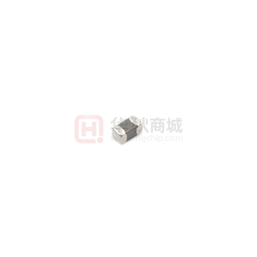
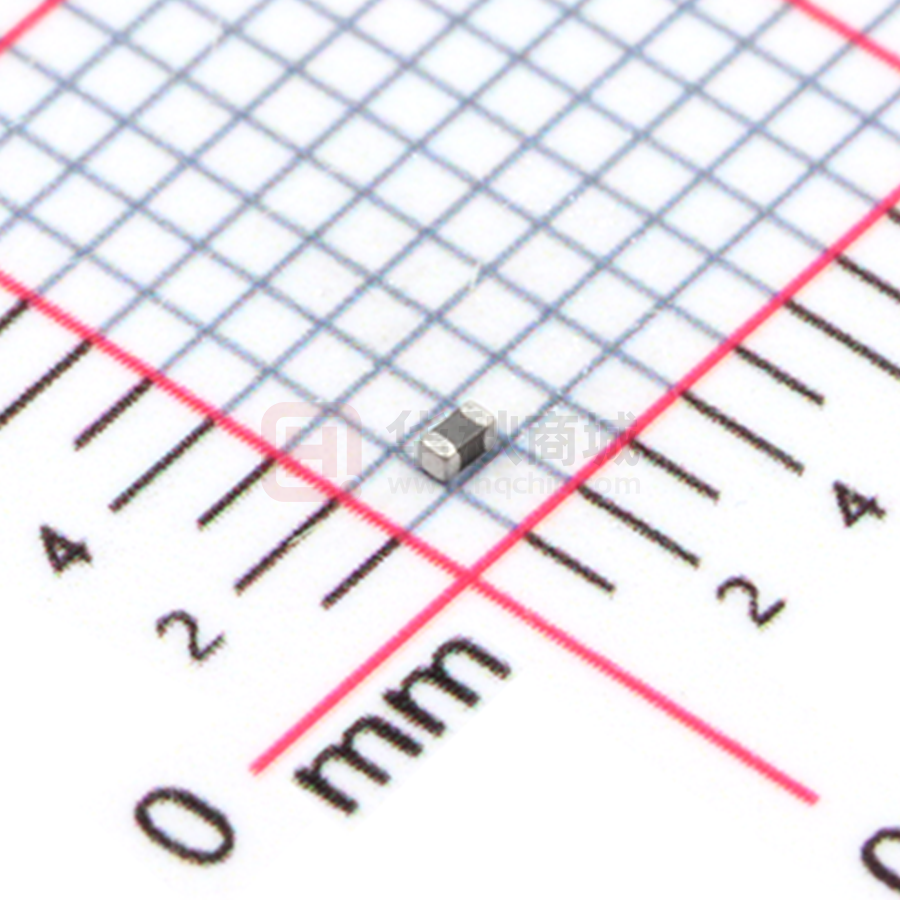


 工商网监
湘ICP备2023018690号
工商网监
湘ICP备2023018690号
