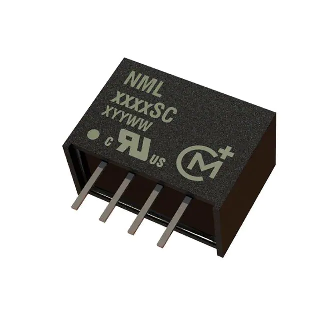
NML Series
www.murata.com
Isolated 2W Single Output DC-DC Converters
SELECTION GUIDE
Order Code
FEATURES
UL 60950 recognised
Nominal
Input
Voltage
V
Output
Voltage
Output
Current
V
mA
Input
Current Efficiency Isolation
at Rated
mA
%
pF
MTTF1
Recommended
Alternative
kHrs
NML0505SC
NML0509SC
NML0512SC
NML0515SC
NML1205SC
NML1212SC
5
5
5
5
12
12
5
9
12
15
5
12
400
222
167
133
400
167
513
492
479
481
207
197
78
81
84
83
81
85
19
27
32
27
28
46
2327
1393
832
481
716
461
NML1209SC
NML1215SC
12
12
9
15
222
133
198
197
84
85
42
54
593
328
Contact Murata
Contact Murata
Conditions
Min.
Typ.
Max.
Units
Continuous operation, 5V input types
Continuous operation, 12V input types
5V input types
12V input types
4.5
10.8
5.0
12.0
33
38
5.5
13.2
V
Typ.
Max.
Units
2.0
W
1.2
8.5
5.2
5.5
8.5
%/%
200
mV p-p
Max.
Units
�
Single isolated output
�
1kVDC isolation ‘Hi Pot Test’
�
Efficiency up to 85%
�
Wide temperature performance at full
2 watt load, –40°C to 85°C
INPUT CHARACTERISTICS
Parameter
�
Industry standard pinout
Voltage range
�
5V & 12V inputs
Reflected ripple current
�
5V, 9V, 12V & 15V outputs
�
Internal SMD construction
OUTPUT CHARACTERISTICS
�
No external components required
Parameter
Conditions
�
Custom solutions available
Rated Power
Voltage Set Point Accuracy
Line regulation
�
Pin compatible with CME, CRE1, CRL2,
LME, MEE1, NKE & NME series
Load Regulation2
TA=-40°C to 85°C
See tolerance envelope
High VIN to low VIN
10% load to rated load, 5V output types
10% load to rated load, 9V output types
10% load to rated load, 12V output types
10% load to rated load, 15V output types
NML0505SC, BW=DC to 20MHz
NML0509SC, BW=DC to 20MHz
NML0512SC, BW=DC to 20MHz
NML0515SC, BW=DC to 20MHz
NML1205SC, BW=DC to 20MHz
NML1209SC, BW=DC to 20MHz
NML1212SC, BW=DC to 20MHz
NML1215SC, BW=DC to 20MHz
�
MTTF up to 2.3 million hours
�
No electrolytic or tantalum capacitors
DESCRIPTION
The NML series of DC-DC Converters is particularly
suited to isolating and/or converting DC power
rails. The galvanic isolation allows the device to be
configured to provide an isolated negative rail in
systems where only positive rails exist. The wide
temperature range guarantees startup from –40°C
and full 2 watt output at 85°C.
Ripple and Noise
Min.
1.0
7.0
4.5
4.5
3.7
96
67
59
53
76
63
53
45
mA p-p
%
ISOLATION CHARACTERISTICS
Parameter
Conditions
Min.
Isolation test voltage
Resistance
Flash tested for 1 second
Viso= 500VDC
1000
10
Typ.
VDC
GΩ
GENERAL CHARACTERISTICS
For full details go to
https://www.murata.com/englobal/products/power/rohs
Parameter
Conditions
Switching frequency
5V input types
12V input types
Min.
Typ.
90
90
Max.
Units
kHz
1. Calculated using MIL-HDBK-217F with nominal input voltage at full load.
All specifications typical at TA=25°C, nominal input voltage and rated output current unless otherwise specified.
www.murata.com
KDC_NML.I01 Page 1 of 8
�NML Series
Isolated 2W Single Output DC-DC Converters
TEMPERATURE CHARACTERISTICS
Parameter
Conditions
Min.
Specification
Storage
All output types
-40
-50
Case Temperature above ambient
Cooling
5V output types
All other output types
Free air convection
Typ.
Max.
Units
85
130
45
36
°C
ABSOLUTE MAXIMUM RATINGS
Lead temperature 1.5mm from case for 10 seconds
Wave Solder
Input voltage VIN, NML05 types
Input voltage VIN, NML12 types
260°C
Wave Solder profile not to exceed the profile recommended in IEC 61760-1
Section 6.1.3. Please refer to application notes for further information.
7V
15V
www.murata.com
KDC_NML.I01 Page 2 of 8
�NML Series
Isolated 2W Single Output DC-DC Converters
TECHNICAL NOTES
ISOLATION VOLTAGE
‘Hi Pot Test’, ‘Flash Tested’, ‘Withstand Voltage’, ‘Proof Voltage’, ‘Dielectric Withstand Voltage’ & ‘Isolation Test Voltage’ are all terms that relate to the same thing, a test voltage,
applied for a specified time, across a component designed to provide electrical isolation, to verify the integrity of that isolation.
Murata Power Solutions NML series of DC-DC converters are all 100% production tested at their stated isolation voltage. This is 1kVDC for 1 second.
A question commonly asked is, “What is the continuous voltage that can be applied across the part in normal operation?”
The NML series has been recognised by Underwriters Laboratory for functional insulation, both input and output should normally be maintained within SELV limits i.e. less than
42.4V peak, or 60VDC. The isolation test voltage represents a measure of immunity to transient voltages and the part should never be used as an element of a safety isolation
system. The part could be expected to function correctly with several hundred volts offset applied continuously across the isolation barrier; but then the circuitry on both sides
of the barrier must be regarded as operating at an unsafe voltage and further isolation/insulation systems must form a barrier between these circuits and any user-accessible
circuitry according to safety standard requirements.
REPEATED HIGH-VOLTAGE ISOLATION TESTING
It is well known that repeated high-voltage isolation testing of a barrier component can actually degrade isolation capability, to a lesser or greater degree depending on materials, construction and environment. The NML series has toroidal isolation transformers, with no additional insulation between primary and secondary windings of enamelled wire.
While parts can be expected to withstand several times the stated test voltage, the isolation capability does depend on the wire insulation. Any material, including this enamel
(typically polyurethane) is susceptible to eventual chemical degradation when subject to very high applied voltages thus implying that the number of tests should be strictly limited. We therefore strongly advise against repeated high voltage isolation testing, but if it is absolutely required, that the voltage be reduced by 20% from specified test voltage.
This consideration equally applies to agency recognised parts rated for better than functional isolation where the wire enamel insulation is always supplemented by a further
insulation system of physical spacing or barriers.
SAFETY APPROVAL
The NML series has been recognised by Underwriters Laboratory (UL) to UL 60950 for functional insulation in a maximum ambient temperature of 85ºC and/or case temperature
limit of 100ºC as measured at any point on the case of the unit (hotspot).
The NML series of converters are not internally fused so to meet the requirements of UL 60950 an anti-surge input line fuse should always be used with ratings as defined below.
NML05xxSC: 0.8A
NML12xxSC: 0.315A
All fuses should be UL recognised and rated to 125V. File number E151252 applies.
RoHS COMPLIANCE INFORMATION
This series is compatible with RoHS soldering systems with a peak wave solder temperature of 260°C for 10 seconds. Please refer to
application notes for further information. The pin termination finish on this product series is Tin Plate, Hot Dipped over Matte Tin with Nickel
replate. The series is backward compatible with Sn/Pb soldering systems.
For further information, please visit www.murata-ps.com/rohs
PART NUMBER STRUCTURE
NML XX XX S C
Series name
RoHS compliant
Input voltage
Package type
Output voltage
S - SIP
D - DIP
M - Surface mount
Z - ZIP
www.murata.com
KDC_NML.I01 Page 3 of 8
�NML Series
Isolated 2W Single Output DC-DC Converters
CHARACTERISATION TEST METHODS
Ripple & Noise Characterisation Method
Ripple and noise measurements are performed with the following test configuration.
C1
1μF X7R multilayer ceramic capacitor, voltage rating to be a minimum of 3 times the output voltage of the DC-DC converter
10μF tantalum capacitor, voltage rating to be a minimum of 1.5 times the output voltage of the DC-DC converter with an ESR of less
than 100mΩ at 100 kHz
C3
100nF multilayer ceramic capacitor, general purpose
R1
450Ω resistor, carbon film, ±1% tolerance
R2
50Ω BNC termination
T1
3T of the coax cable through a ferrite toroid
RLOAD
Resistive load to the maximum power rating of the DC-DC converter. Connections should be made via twisted wires
Measured values are multiplied by 10 to obtain the specified values.
C2
Differential Mode Noise Test Schematic
DC/DC Converter
OSCILLOSCOPE
C1 C2 C3
+
SUPPLY
Input
-
+
R1
T1
R2
Y INPUT
Output
-
R LOAD
APPLICATION NOTES
Minimum load
The minimum load to meet datasheet specification is 10% of the full rated load across the specified input voltage range. Lower than 10% minimum loading will result
in an increase in output voltage, which may rise to typically double the specified output voltage if the output load falls to less than 5%.
Capacitive loading and start up
Typical start up times for this series, with a typical input voltage rise time of 2.2μs and output capacitance of 10μF, are shown in the table below. The product
series will start into a capacitance of 47μF with an increased start time, however, the maximum recommended output capacitance is 10μF.
NML0505SC
NML0509SC
NML0512SC
NML0515SC
NML1205SC
NML1209SC
NML1212SC
NML1215SC
Start-up time
μs
790
1154
2265
2998
396
880
1156
2394
Typical Start-Up Wave Form
www.murata.com
KDC_NML.I01 Page 4 of 8
�NML Series
Isolated 2W Single Output DC-DC Converters
APPLICATION NOTES (Continued)
Output Ripple Reduction
By using the values of inductance and capacitance stated, the output ripple at the rated load is lowered to 5mV p-p max.
Component selection
Capacitor: It is required that the ESR (Equivalent Series Resistance) should be as low as possible, ceramic types are recommended.
The voltage rating should be at least twice (except for 15V output), the rated output voltage of the DC-DC converter.
Inductor: The rated current of the inductor should not be less than that of the output of the DC-DC converter. At the rated current, the DC resistance of the
inductor should be such that the voltage drop across the inductor is 20MHz.
L
DC
Power
Source
NML0505SC
NML0509SC
NML0512SC
NML0515SC
NML1205SC
NML1209SC
NML1212SC
NML1215SC
L, μH
22
47
47
68
22
47
47
68
Inductor
SMD
82223
82473
82473
82683
82223
82473
82473
82683
C
Load
DC
Through Hole
11R223C
11R473C
11R473C
11R683C
11R223C
11R473C
11R473C
11R683C
Capacitor
C, μF
2.2uF
1uF
2.2uF
3.3uF
2.2uF
1uF
2.2uF
3.3uF
www.murata.com
KDC_NML.I01 Page 5 of 8
�NML Series
Isolated 2W Single Output DC-DC Converters
TOLERANCE ENVELOPE
The voltage tolerance envelope shows typical load regulation characteristics for this product series. The tolerance envelope is the maximum output voltage variation due to
changes in output loading.
All variants
10%
Typica
l
Output Voltage
5%
Load L
ine
2.5%
0%
-2.5%
-7.5%
10
25
50
75
Output Load Current (%)
100
TEMPERATURE DERATING GRAPH
Output Power (W)
3
2
1
0
-40
85°C
Safe Operating Area
100
50
0
Ambient Temperature (°C)
150
www.murata.com
KDC_NML.I01 Page 6 of 8
�NML Series
Isolated 2W Single Output DC-DC Converters
PACKAGE SPECIFICATIONS
MECHANICAL DIMENSIONS
PIN CONNECTIONS - 4 PIN SIP
SIP Package
Pin
Function
1
2
3
4
-VIN
+VIN
-VOUT
+VOUT
14.00±0.15 [0.551±0.006]
10.00±0.25 [0.394±0.010]
4.10±0.5 [0.161±0.020]
0.40 [0.016] MIN
TUBE OUTLINE DIMENSIONS
NML
0505SC
XYYWW
1
2
3
S
4
12.43 [0.489]
2.54 [0.100]
(3.44 [0.135])
9.3 [0.366]
18.0 [0.709]
0.50±0.05 [0.020±0.002]
0.25±0.05 [0.010±0.002]
(1.13 [0.044])
7.50±0.25 [0.295±0.010]
5.0 [0.197]
Weight: 2.0g
All dimensions in mm (inches). Controlling dimension is mm.
All pins on a 2.54 (0.100) pitch and within ±0.1 (0.004) of true position from pin 1 at seating plane ‘S’
Unless otherwise specified all dimensions in mm [inches] ±0.55mm [0.022].
Tube Length : 520mm [20.472] ±2.0 [0.079].
Tube Quantity : 35
RECOMMENDED FOOTPRINT DETAILS
2.54 [0.100]
x4 HOLES
Ø 0.045
0.039
Ø 1.15
1.00
[
]
2.54 [0.100]
Unless otherwise stated all dimensions in mm (inches) ±0.5mm.
www.murata.com
KDC_NML.I01 Page 7 of 8
�NML Series
Isolated 2W Single Output DC-DC Converters
DISCLAIMER
Unless otherwise stated in the datasheet, all products are designed for standard commercial and industrial applications and NOT for safety-critical and/or life-critical
applications.
Particularly for safety-critical and/or life-critical applications, i.e. applications that may directly endanger or cause the loss of life, inflict bodily harm and/or loss or severe
damage to equipment/property, and severely harm the environment, a prior explicit written approval from Murata is strictly required. Any use of Murata standard products for any safety-critical, life-critical or any related applications without any prior explicit written approval from Murata shall be deemed unauthorised use.
These applications include but are not limited to:
•
Aircraft equipment
•
Aerospace equipment
•
Undersea equipment
•
Power plant control equipment
•
Medical equipment
•
Transportation equipment ( automobiles, trains, ships, etc.)
•
Traffic signal equipment
•
Disaster prevention / crime prevention equipment
•
Data Processing equipment
Murata makes no express or implied warranty, representation, or guarantee of suitability, fitness for any particular use/purpose and/or compatibility with any application or device of the buyer, nor does Murata assume any liability whatsoever arising out of unauthorised use of any Murata product for the application of the buyer. The
suitability, fitness for any particular use/purpose and/or compatibility of Murata product with any application or device of the buyer remain to be the responsibility and
liability of the buyer.
Buyer represents and agrees that it has all the necessary expertise to create and implement safeguards that anticipate dangerous consequences of failures, monitor failures and their consequences, lessen the likelihood of failures that might cause harm, and take appropriate remedial actions. Buyer will fully indemnify and hold
Murata, its affiliated companies, and its representatives harmless against any damages arising out of unauthorised use of any Murata products in any safety-critical and/
or life-critical applications.
Remark: Murata in this section refers to Murata Manufacturing Company and its affiliated companies worldwide including, but not limited to, Murata Power Solutions.
This product is subject to the following operating requirements
and the Life and Safety Critical Application Sales Policy:
Refer to: https://www.murata.com/en-eu/products/power/requirements
Murata Power Solutions (Milton Keynes) Ltd. makes no representation that the use of its products in the circuits described herein, or the use
of other technical information contained herein, will not infringe upon existing or future patent rights. The descriptions contained herein do
not imply the granting of licenses to make, use, or sell equipment constructed in accordance therewith. Specifications are subject to change
without notice.
© 2022 Murata Power Solutions (Milton Keynes) Ltd.
www.murata.com
KDC_NML.I01 Page 8 of 8
�


 工商网监
湘ICP备2023018690号
工商网监
湘ICP备2023018690号

