www.murata-ps.com
s
NTF Series
OLLEETTEE
BSSO
OB
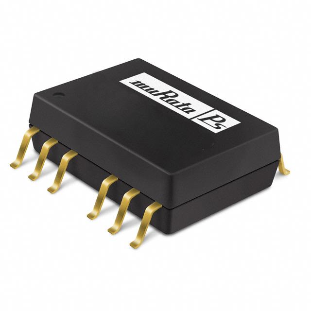
Isolated 1W Wide Input DC/DC Converters
SELECTION GUIDE
2
Order Code
Input
Output
Input Current
Output
Voltage
Current
Voltage
Nominal
100% Load 0% Load Shutdown 100% Load
V
V
mA
mA
μA
mA
�
Efficiency from 60.5%
NTFS0505MC
NTFS0512MC
NTFS0515MC
NTFS1205MC
NTFS1212MC
NTFS1215MC
NTFS2405MC
NTFS2412MC
NTFS2415MC
�
Wide temperature performance –40°C
to 85°C
INPUT CHARACTERISTICS
FEATURES
�
RoHS compliant
�
UL 94V-0 Package material
Parameter
�
Lead frame technology
Voltage range
5
5
5
12
12
12
24
24
24
�
5V, 12V, & 24V Input
�
5V, 12V & 15V Output
Reflected ripple current
�
Internal SMD construction
5
12
15
5
12
15
5
12
15
200
83
66
200
83
66
200
83
66
25
30
60
10
12
15
6
8
9
72
55
80
70
34
33
96
48
50
Conditions
Continuous operation, 5V input types
Continuous operation, 12V input types
Continuous operation, 24V input types
xx05 output types
xx12 output types
xx24 output types
Efficiency
Min.
MTTF
Typ.
%
kHrs
320
300
320
110
130
120
120
60
60
59.0
63.5
60.5
68.0
62.0
62.0
65.0
65.0
65.0
62
67
63
73
66
66
70
68
67
921
1118
869
1281
1175
1283
1379
1278
1223
Min.
Typ.
Max.
Units
4
9
18
5
12
24
12
6
6
6
15
36
V
Typ.
Max.
Units
mA p-p
�
1kVDC Isolation
OUTPUT CHARACTERISTICS
�
MTTF up to 1.4 million hours
Parameter
Conditions
�
Power density 0.7W/cm3
Voltage set point
accuracy
With external input/output capacitors
±1
±2
%
Line regulation
Low line to high line,
0.2
1
%
Load regulation
10% load to 100% load, with external input/
output capacitors
0.1
1
%
100
150
+10
mV p-p
%VOUT
Typ.
Max.
Units
700
kHz
�
Multi layer ceramic capacitors
PRODUCT DESCRIPTION
The NTF 1W series of surface mount DC/DC
converters offer a tightly regulated output voltage
in a true surface mount device, available with
three wide input voltage ranges of 4-6V, 9-15V
and 18-36V. The NTF series’ employs leadframe
technology and transfer moulding techniques to
bring all of the benefits of IC style packaging to
hybrid circuitry. Co-planarity of the lead positions
is based upon IEC 191-6:1990. The devices are
suitable for all applications where high volume
production is envisaged.
Ripple & Noise
Voltage trim range
Min.
BW=DC to 20MHz, all output types
-10
GENERAL CHARACTERISTICS
Parameter
Conditions
Switching frequency
Min.
50
ABSOLUTE MAXIMUM RATINGS
Short-circuit protection
Lead temperature 1.5mm from case for 10 seconds
Input voltage VIN, NTF05 types
Input voltage VIN, NTF12 types
Input voltage VIN, NTF24 types
15s
245°C
10V
17.5V
40V
1 Calculated using MIL-HDBK-217F with nomial input voltage at full load (ground benign) at 25ºC.
2 If components are required in tape and reel format suffix order code with -R, e.g. NTF0505MC-R.
All specifications typical at TA=25ºC, nominal input voltage and rated output current unless otherwise specified.
For full details go to
www.murata-ps.com/rohs
www.murata-ps.com/support
KDC_NTF.D01 Page 1 of 8
�NTF Series
Isolated 1W Wide Input DC/DC Converters
TEMPERATURE CHARACTERISTICS
Parameter
Conditions
Min.
Operation
Storage
Cooling
Case temperature rise above
ambient
See derating graphs
-40
-50
Typ.
Max.
Units
85
130
Free air convection
30
ºC
ISOLATION CHARACTERISTICS
Parameter
Conditions
Min.
Isolation test voltage
Resistance
Capacitance
Flash tested for 1 second
Viso= 500VDC
1000
1
Typ.
10
25
Max.
Units
VDC
GΩ
pF
TECHNICAL NOTES
ISOLATION VOLTAGE
‘Hi Pot Test’, ‘Flash Tested’, ‘Withstand Voltage’, ‘Proof Voltage’, ‘Dielectric Withstand Voltage’ & ‘Isolation Test Voltage’ are all terms that relate to the same thing, a test voltage,
applied for a specified time, across a component designed to provide electrical isolation, to verify the integrity of that isolation.
Murata Power Solutions NTF series of DC/DC converters are all 100% production tested at their stated isolation voltage. This is 1kVDC for 1 second.
A question commonly asked is, “What is the continuous voltage that can be applied across the part in normal operation?”
For a part holding no specific agency approvals, such as the NTF series, both input and output should normally be maintained within SELV limits i.e. less than 42.4V peak, or
60VDC. The isolation test voltage represents a measure of immunity to transient voltages and the part should never be used as an element of a safety isolation system. The part
could be expected to function correctly with several hundred volts offset applied continuously across the isolation barrier; but then the circuitry on both sides of the barrier must
be regarded as operating at an unsafe voltage and further isolation/insulation systems must form a barrier between these circuits and any user-accessible circuitry according to
safety standard requirements.
REPEATED HIGH-VOLTAGE ISOLATION TESTING
It is well known that repeated high-voltage isolation testing of a barrier component can actually degrade isolation capability, to a lesser or greater degree depending on materials,
construction and environment. The NTF series has toroidal isolation transformers, with no additional insulation between primary and secondary windings of enameled wire. While
parts can be expected to withstand several times the stated test voltage, the isolation capability does depend on the wire insulation. Any material, including this enamel (typically
polyurethane) is susceptible to eventual chemical degradation when subject to very high applied voltages thus implying that the number of tests should be strictly limited. We
therefore strongly advise against repeated high voltage isolation testing, but if it is absolutely required, that the voltage be reduced by 20% from specified test voltage.
This consideration equally applies to agency recognized parts rated for better than functional isolation where the wire enamel insulation is always supplemented by a further
insulation system of physical spacing or barriers.
www.murata-ps.com/support
KDC_NTF.D01 Page 2 of 8
�NTF Series
Isolated 1W Wide Input DC/DC Converters
TEMPERATURE DERATING
NTFS0505
NTFS0512
120
120
100
100
Hi Vin
Hi Vin
Nom Vin
Nom Vin
80
Maximum load (%)
Maximum load (%)
80
60
Lo Vin
40
20
Lo Vin
60
40
20
0
-40
-20
0
20
40
60
0
-40
80
-20
0
Temperature (ºC)
20
40
60
80
Temperature (ºC)
NTFS0515
NTFS1205
120
120
Hi Vin
100
100
Hi Vin
Nom Vin
Nom Vin
80
Maximum load (%)
Maximum load (%)
80
Lo Vin
60
40
20
0
-40
60
Lo Vin
40
20
-20
0
20
40
60
0
-40
80
-20
0
Temperature (ºC)
20
40
60
80
Temperature (ºC)
NTFS1212
NTFS1215
120
120
Hi Vin
Hi Vin
100
100
Nom Vin
Nom Vin
80
Maximum load (%)
Maximum load (%)
80
Lo Vin
60
40
20
0
-40
60
Lo Vin
40
20
-20
0
20
Temperature (ºC)
40
60
80
0
-40
-20
0
20
40
60
80
Temperature (ºC)
www.murata-ps.com/support
KDC_NTF.D01 Page 3 of 8
�NTF Series
Isolated 1W Wide Input DC/DC Converters
TEMPERATURE DERATING
NTFS2405
NTFS2412
120
120
100
100
Hi Vin
Hi Vin
Nom Vin
60
Lo Vin
40
20
0
-40
Nom Vin
80
Maximum load (%)
Maximum load (%)
80
60
Lo Vin
40
20
-20
0
20
40
60
80
Temperature (ºC)
0
-40
-20
0
20
40
60
80
Temperature (ºC)
NTFS2415
120
Hi Vin
100
Nom Vin
Maximum load (%)
80
60
Lo Vin
40
20
0
-40
-20
0
20
40
60
80
Temperature (ºC)
www.murata-ps.com/support
KDC_NTF.D01 Page 4 of 8
�NTF Series
Isolated 1W Wide Input DC/DC Converters
MINIMUM LOAD
The graphs show the minimum load to meet datasheet specification. The NTF series will operate to zero load, however, the NTF series may not meet all datasheet
specifications.
NTFS12XX
30
30
25
25
Minimum Load (%)
Minimum Load (%)
NTFS05XX
20
12V&15V
5V
15
12V&15V
5V
15
10
10
5
5
0
20
0
4
4.2
4.4
4.6
4.8
5
5.2
Input Voltage (V)
5.4
5.6
5.8
6
9
10
11
12
13
Input Voltage (V)
14
15
NTFS24XX
50
45
Minimum Load (%)
40
5V
35
30
25
20
12V and 15V
15
10
5
0
18
21
24
27
30
33
36
Input Voltage (V)
RoHS COMPLIANCE INFORMATION
This series is compatible with RoHS soldering systems with a peak reflow solder temperature of 245ºC and time above liquidus of 217ºC
for 60 seconds. The pin termination finish on this product series is Gold, plating thickness 0.05 microns minimum. The series is backward
compatible with Sn/Pb soldering systems.
For further information, please visit www.murata-ps.com/rohs
www.murata-ps.com/support
KDC_NTF.D01 Page 5 of 8
�NTF Series
Isolated 1W Wide Input DC/DC Converters
APPLICATION NOTES
Recommended input & output capacitors
Value
Although these converters will work without external capacitors, they are
necessary in order to guarantee the full parametric performance over the full
line and load range. All parts have been tested and characterized using the
following values and test circuit.
CIN
10μF, 200V
good low esr capacitor
COUT
22μF, 16V
good low esr capacitor
Test circuit, 5V, 12V and 15V output
+ VOUT
+ VIN
CIN
NTF
COUT
- VOUT
- VIN
ON/OFF Pin
This provides an OFF function, which puts the converter into a low power mode. When the pin is un-connected, the converter is on. The circuit used must be able to sink a peak
curent of 50mA to guarantee turning the converter off. The circuit should be an open collector arrangement, an example circuit is shown below. Voltages should not be applied
directly to the ON/OFF pin. The BC547 should be fitted close to the NTF ON/OFF pin to prevent the addition of excess wiring capacitance.
CTRL
47kΩ
BC547
VCONTROL
NTF
100nF
- VIN
CONTROL PIN CIRCUIT INPUT VOLTAGE VCONTROL
Min.
Max.
Module ON
0
0.2
Module OFF
1.6
30
Units
V
V
Output voltage adjustment
The trim resistor equations are:
RDOWN = (VDOWN - L) x G
VNOM - VDOWN
RUP =
GxL
VUP - L - K
TRIM UP
Where:
NTFS0505MC
NTFS1205MC, NTFS2405MC
NTFSXX12MC
NTSFXX15MC
G
L
K
30100
100000
38300
49900
1.24
1.24
2.5
2.5
3.76
3.76
9.5
12.5
TRIM DOWN
+VIN
+VOUT
+VOUT
+VIN
RDOWN
NTF
TRIM
NTF
TRIM
RUP
-VOUT
-VOUT
When the output voltage is trimmed up, output current must be derated so that the maximum output power is not exceeded.
www.murata-ps.com/support
KDC_NTF.D01 Page 6 of 8
�NTF Series
Isolated 1W Wide Input DC/DC Converters
PACKAGE SPECIFICATIONS
MECHANICAL DIMENSIONS
PIN CONNECTIONS
17.78 (0.700)
15.24 (0.600)
18.03 (0.710) 17.53(0.690)
26 24
22
18
16
14
DETAIL A
12.70 (0.500)
REFERENCE PLANE
NTFS0505MC
0.50 (0.020)
XYYWW
1
3
5
±5.0°
x12 PINS
1.0565-1.3565 (0.0416-0.0534)
0.2 (0.008)
9
11
S
13
12 PINS
0.74 (0.029) 0.64 (0.025)
0.008 (0.2)
2.54 (0.100)
S
6.30 (0.248) 5.80 (0.228)
Function
1
3
5
9
11
-VIN
+VIN
NA
NA
-VOUT
13
+VOUT
14
16
18
22
24
26
NA
TRIM
NA
ON/OFF
NA
NA
2.74 (0.108) MAX
DETAIL A
3.30 (0.130)
6.55 (0.258)
5.90 (0.232)
Pin
NA - Not available for electrical
connection.
S
SEATING PLANE
0.25 (0.010)
0.10 (0.004)
0.30 (0.012)
0.20 (0.008)
All dimensions in mm ±0.25mm (inches ±0.01). All pins on a 2.54 (0.1) pitch.
Weight: 2.8g
TUBE OUTLINE DIMENSIONS
15.24 (0.600)
5.8
20.80 (0.819)
2.00 (0.079)
16.50 (0.650)
2.54 (0.100)
All dimensions in mm ±0.5 (inches ±0.02)
1.00 (0.039) MIN
+0.031
+0.8
-0.60 (0.228 -0.024 )
0.60±0.15
(0.024±0.006)
RECOMMENDED FOOTPRINT DETAILS
14.40 (0.567)
x12 PINS
0.1 (0.004)
S
1.52 (0.06) MAX
+0.006
+0.15
2.85 -0.25 (0.112 -0.010 )
All dimensions in mm±0.5 (inches ±0.02).
Tube length : 475±2.0 (18.70±0.079).
Tube Quantity : 25
www.murata-ps.com/support
KDC_NTF.D01 Page 7 of 8
�NTF Series
Isolated 1W Wide Input DC/DC Converters
TAPE & REEL SPECIFICATIONS
TAPE OUTLINE DIMENSIONS
330
(12.99) MAX
COVER TAPE
±0.05 (0.002)
+0.004
+0.10
Ø1.50 -0.00 (Ø0.059 -0.000 )
REEL OUTLINE DIMENSIONS
18.33 (0.722)
0.60 (0.024) MAX
24.00 (0.945)
18.43 (0.726)
DIRECTION OF UNREELING
10.00 (0.394)
Ø2.00 (Ø0.079) MIN
4.00 (0.157)
2.00 (0.079)
13.50 (0.531)
Ø 12.80 (0.504)
NTFS0505MC
32.00±0.30 (1.260±0.012)
All dimensions in mm±0.5 (inches ±0.02)
6.50 (0.256)
7.20 (0.284)
28.40 (1.118)
0.20±0.05 (0.008±0.002)
14.20 (0.559)
+0.002
+0.05
R0.030 -0.000 (R0.75 -0.00 )
XYYWW
1.75 (0.069)
38.4 (1.512) MAX
31.9-35.4(1.256-1.394) (AT HUB SECTION)
100
Ø (3.94) MIN
All dimensions in mm±0.5 (inches ±0.02)
REEL PACKAGING DETAILS
TRAILER SECTION
160 (6.30) MIN
All dimensions in mm±0.5 (inches ±0.02)
Reel Quantity : 400
Murata Power Solutions, Inc.
11 Cabot Boulevard, Mansfield, MA 02048-1151 U.S.A.
ISO 9001 and 14001 REGISTERED
GOODS ENCLOSURE
SECTION
CARRIER TAPE START
100 (3.94) MIN
LEADER SECTION
400 (15.75) MIN
This product is subject to the following operating requirements
and the Life and Safety Critical Application Sales Policy:
Refer to: http://www.murata-ps.com/requirements/
Murata Power Solutions, Inc. makes no representation that the use of its products in the circuits described herein, or the use of other
technical information contained herein, will not infringe upon existing or future patent rights. The descriptions contained herein do not imply
the granting of licenses to make, use, or sell equipment constructed in accordance therewith. Specifications are subject to change without
notice.
© 2014 Murata Power Solutions, Inc.
www.murata-ps.com/support
KDC_NTF.D01 Page 8 of 8
�


 工商网监
湘ICP备2023018690号
工商网监
湘ICP备2023018690号
