www.murata-ps.com
OKI-78SR Series
Fixed Output 1.5 Amp SIP DC/DC Converters
PRODUCT OVERVIEW
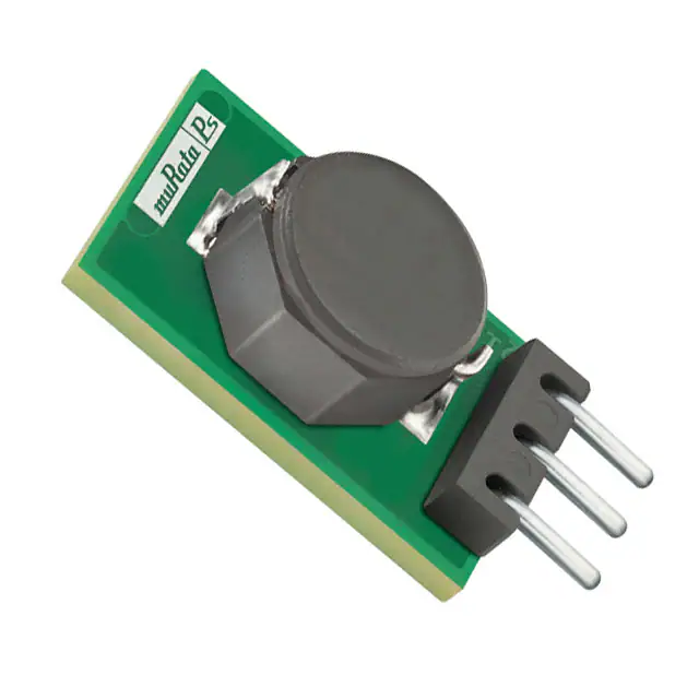
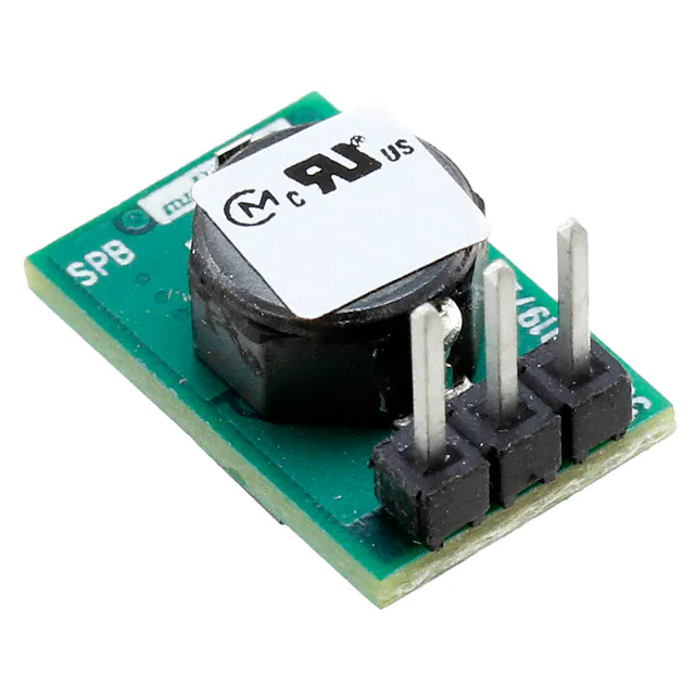
Fabricated on a 0.41 by 0.65 inch (10.4 by 16.5 mm) Single Inline Package (SIP) module, the OKI78SR series are non-isolated switching regulator (SR) DC/DC power converters for embedded applications. The fixed single output converters offer both tight regulation and high efficiency directly at the power usage site and are a direct plug-in replacement for TO-220 package 78xx series linear regulators. Typically, no extra outside components are required. Two nominal output voltages are offered (3.3 and 5 VDC), each with 1.5 Amp maximum output. Based on fixed-frequency buck switching topology, the high efficiency means very low heat and little electrical noise, requiring no external components. The ultra wide input range is 7 to 36 Volts DC. Protection features include input undervoltage and short circuit protection, overcurrent and over temperature shut down. All standard safety and EMI/RFI certifications are available. RoHS-6 (no lead) hazardous material compliance is specified as standard.
PRELIMINARY
Typical unit
FEATURES FEATURES
■ ■ ■ ■
Ultra wide 7 to 36 VDC input range Fixed Outputs of 3.3 or 5 VDC up to 1.5 Amps Vertical SIP-mount, small footprint package “No heat sink” direct replacement for 3-terminal 78xx-series linear regulators High efficiency with no external components Short circuit protection Outstanding thermal derating performance UL/EN/IEC 60950-1 safety approvals Contents Description, Connection Diagram, Photograph Ordering Guide, Model Numbering, Product Labeling Mechanical Specifications, Input/Output Pinout Detailed Electrical Specifications Performance Data and Oscillograms Soldering Guidelines, Application Notes Page 1 2 3 4 5 9
■ ■ ■ ■
Connection Diagram
+Vin F1 Controller +Vout
External DC Power Source
Reference and Error Amplifier
Common Figure 1. OKI-78SR Note: Murata Power Solutions strongly recommends an external input fuse, F1. See specifications.
Common
For full details go to www.murata-ps.com/rohs
www.murata-ps.com
22 Mar 2010
email: sales@murata-ps.com
MDC_OKI-78SR-W36.A01_D6 Page 1 of 10
�OKI-78SR Series
PRELIMINARY
Performance Specifications and Ordering Guide
ORDERING GUIDE Output VOUT (Volts) 3.3 5 IOUT (Amps Power max) (Watts)
1.5
Fixed Output 1.5 Amp SIP DC/DC Converters
Input Regulation (Max.) Line ±0.25% ±0.25% Load ±0.25% ±0.25% VIN Nom. Range (Volts) (Volts)
12
R/N (mVp-p) Max. 40 75
Root Model OKI-78SR3.3/1.5-W36-C OKI-78SR5/1.5-W36-C
IIN, IIN, no load full load (mA) (Amps)
5 0.48
Efficiency Package Min.
84%
Typ.
85.5%
➀
4.95 7.5
7-36 7-36
0.41 x 0.65 x 0.3 (10.4 x 16.5 x 7.62) 0.41 x 0.65 x 0.3 (10.4 x 16.5 x 7.62)
1.5
12
5
0.69
89%
90.5%
➀ Dimensions are in inches (mm). ➁ All specifications are at nominal line voltage, Vout = nominal and full load, +25 ˚C., with no external capacitor,
unless otherwise noted.
Product Label Because of the small size of these products, the product label contains a character-reduced code to indicate the model number and manufacturing date code. Not all items on the label are always used. Please note that the label differs from the product photograph on page 1. Here is the layout of the label:
Model Number OKI-78SR3.3/1.5-W36-C OKI-78SR5/1.5-W36-C Product Code I33115 I50115
The manufacturing date code is four characters:
Mfg. date code XXXXXX YMDX Rev. Product code Revision level
Figure 2. Label Artwork Layout
First character – Last digit of manufacturing year, example 2009 Second character – Month code (1 through 9 and O through D) Third character – Day code (1 through 9 = 1 to 9, 10 = O and 11 through 31 = A through Z) Fourth character – Manufacturing information
The label contains three rows of information: First row – Murata Power Solutions logo Second row – Model number product code (see table) Third row – Manufacturing date code and revision level
www.murata-ps.com
22 Mar 2010
email: sales@murata-ps.com
MDC_OKI-78SR-W36.A01_D6 Page 2 of 10
�OKI-78SR Series
PRELIMINARY
MECHANICAL SPECIFICATIONS
Fixed Output 1.5 Amp SIP DC/DC Converters
0.41 (10.4) 0.205 (5.2) REF C L
0.30 (7.6) 0.16 (4.1) 0.06 (1.5) REF
0.65 (16.5) Pin #3 0.13 (3.3) Pin #1 0.100 (2.5) 0.200 (5.1) Pin #1 0.030±0.002 0.05 (1.3)
PIN MATERIAL: COPPER ALLOY PIN FINISH: PURE MATTE TIN 100-300 u" OVER 75-150 u" NICKEL
Pin #1
INPUT/OUTPUT CONNECTIONS OKI-78SR
Dimensions are in inches (mm shown for ref. only).
Third Angle Projection
Pin 1 2 3
Function Positive Input Common (Ground) Positive Output
Tolerances (unless otherwise specified): .XX ± 0.02 (0.5) .XXX ± 0.010 (0.25) Angles ± 1˚ Components are shown for reference only.
Figure 2. OKI-78SR Mechanical Outline
www.murata-ps.com
22 Mar 2010
email: sales@murata-ps.com
MDC_OKI-78SR-W36.A01_D6 Page 3 of 10
�OKI-78SR Series
PRELIMINARY
Performance and Functional Specifications
All specifications are typical unless noted. See Note 1
Fixed Output 1.5 Amp SIP DC/DC Converters
Physical See Mechanical Specifications [11] 0.07 ounces (2 grams) UL/cUL 60950-1 CSA-C22.2 No. 60950-1 IEC/EN 60950-1
Input Input Voltage Range See Ordering Guide. Recommended External Fuse 2 Amps fast blow Reverse Polarity Protection (Note 9) None. Install an external fuse. Not isolated. The input and output share a Isolation (note 5) common return. 4.85V. min., 6.0V. max (OKI-78SR3.3/1.5-W36) Start-Up Voltage 6.5V. min., 7.5V. max. (OKI-78SR5/1.5-W36) 4.15V.min., 4.5V. max. (OKI-78SR3.3/1.5-W36) Undervoltage Shutdown (Note 13) 3.5V. min., 5.0V. max. (OKI-78SR5/1.5-W36) Overvoltage Shutdown None Internal Input Filter Type Capacitive Input Current: Full Load Conditions See Ordering Guide Inrush Transient 0.16 A2Sec. Shutdown Mode (Off, UV, OT) 1 mA Output in Short Circuit 5 mA No Load 5 mA 0.8 Amps (OKI-78SR3.3/1.5-W36) Low Line (Vin=Vmin, Vout=nom) 1.16 Amps (OKI-78SR5/1.5-W36) Reflected (Back) Ripple Current 10 mA pk-pk (OKI-78SR3.3/1.5-W36) (Note 2) 49 mA pk-pk (OKI-78SR5/1.5-W36)
Output Voltage Output Current Range Minimum Loading (Note 12) Maximum Output Power Accuracy (50% load) Overvoltage Protection (Note 7) Temperature Coefficient Ripple/Noise (20 MHz bandwidth) Line/Load Regulation Efficiency Maximum Capacitive Loading Cap-ESR=0.001 to 0.01 Ohms Cap-ESR >0.01 Ohms Current Limit Inception (98% of Vout setting, after warm up) Short Circuit Mode (Notes 6, 12) Short Circuit Current Output Protection Method Short Circuit Duration Prebias Startup
Outline Dimensions Weight Safety
Absolute Maximum Ratings Input Voltage, Continuous or transient 36 Volts max. Input Reverse Polarity Protection None. Install external fuse. Current-limited. Devices can withstand sustained Output Current short circuit without damage. Storage Temperature -40 to +125 deg. C.
Specification Notes:
(1) All specifications are typical unless noted. General conditions for Specifications are +25 deg.C ambient temperature, Vin=nominal, Vout=nominal, full rated load. Adequate airflow must be supplied for extended testing under power. See Derating curves. All models are tested and specified with no external capacitors. All models are stable and regulate within spec under no-load conditions. (2) (3) Input Back Ripple Current is tested and specified over a 5 Hz to 20 MHz bandwidth. Input filtering is Cin=2 x 100 μF, Cbus=1000 μF, Lbus=1 μH. All caps are low ESR types. Note that Maximum Power Derating curves indicate an average current at nominal input voltage. At higher temperatures and/or lower airflow, the DC/DC converter will tolerate brief full current outputs if the total RMS current over time does not exceed the Derating curve. All Derating curves are presented near sea level altitude. Be aware of reduced power dissipation with increasing altitude. Mean Time Before Failure is calculated using the Telcordia (Belcore) SR-332 Method 1, Case 3, ground fixed conditions, Tpcboard=+25 deg.C, full output load, natural air convection. The input and output are not isolated. They share a single COMMON power and signal return. Short circuit shutdown begins when the output voltage degrades approximately 2% from the selected setting. Output current limit and short circuit protection are non-latching. When the overcurrent fault is removed, the converter will immediately recover. The output is not intended to sink appreciable reverse current. “Hiccup” overcurrent operation repeatedly attempts to restart the converter with a brief, full-current output. If the overcurrent condition still exists, the restart current will be removed and then tried again. This short current pulse prevents overheating and damaging the converter. Input Fusing: If reverse polarity is accidentally applied to the input, to ensure reverse input protection, always connect an external input fast-blow fuse in series with the +Vin input. Use approximately twice the full input current rating with nominal input voltage.
Output See Ordering Guide 0 to 1.5 Amps No minimum load 5.15 Watts (OKI-78SR3.3/1.5-W36) 7.8 Watts (OKI-78SR5/1.5-W36) ±4 % of Vnom None ±0.02% per °C. of Vout range See Ordering Guide and note 12 See Ordering Guide and note 10 See Ordering Guide and performance graphs
300 μF 3300 μF 3.5 Amps 10 mA Hiccup autorecovery upon overload removal. (Note 8) Continuous, no damage (output shorted to ground) The converter will start up if the external output voltage is less than Vnominal.
(4) (5) (6)
(7) (8)
(9)
(10) Regulation specifications describe the deviation as the line input voltage or output load current is varied from a nominal midpoint value to either extreme. (11) CAUTION: Since the converter is mounted on the end by its pins, do not subject it to high vibration, shock or acceleration. (12) Output noise may be further reduced by installing an external filter. Do not exceed the maximum output capacitance. At zero output current and no external capacitor, the output may contain low frequency components which exceed the ripple specification. The output may be operated indefinitely with no load. (13) The input must remain above the Undervoltage Shutdown (UVLO) voltage specification at all times to avoid an unplanned turn off.
Dynamic Characteristics Dynamic Load Response (50% to 100% load step, no external caps) di/dt = 1 A/μSec 25 μSec settling time to within ±2% of final value Peak deviation 100 mV Switching Frequency 500 KHz Environmental Calculated MTBF (Note 4) TBC Operating Ambient Temperature Range Full power, with derating [3] -40 to +85 °C. see derating curves. Storage Temperature Range -55 to +125 °C. Relative Humidity to 85%/+85 °C.
www.murata-ps.com
22 Mar 2010
email: sales@murata-ps.com
MDC_OKI-78SR-W36.A01_D6 Page 4 of 10
�OKI-78SR Series
PRELIMINARY
PERFORMANCE DATA – OKI-78SR3.3/1.5-W36
Efficiency vs. Line Voltage and Load Current @ +25˚C. (Vout = Vnom.)
100 90 80 70 Efficiency (%) 60 50 40 30 20 10 0 0 0.2 0.4 0.6 0.8 1 1.2 1.4 1.6 Load Curre nt (Amps)
0.00 20 25 30 35 40 45 50 55 60 65 70 75 80 85 2.00
Fixed Output 1.5 Amp SIP DC/DC Converters
Maximum Current Temperature Derating at sea level (Vin=7V. to 36V.)
Output Current (Amps)
VIN = 7V VIN = 12V VIN = 36V
65 LFM 1.00
Ambient Temperature (ºC)
Output Ripple and Noise (Vin=7V, Vout=nominal, Iout=1.6A, Cload=0, Ta=+25˚C., ScopeBW=100MHz)
Output Ripple and Noise (Vin=12V, Vout=nominal, Iout=1.6A, Cload=0, Ta=+25˚C., ScopeBW=100MHz)
Output Ripple and Noise (Vin=36V, Vout=nominal, Iout=1.6A, Cload=0, Ta=+25˚C., ScopeBW=100MHz)
www.murata-ps.com
22 Mar 2010
email: sales@murata-ps.com
MDC_OKI-78SR-W36.A01_D6 Page 5 of 10
�OKI-78SR Series
PRELIMINARY
PERFORMANCE DATA – OKI-78SR3.3/1.5-W36
Step Load Transient Response (Vin=7V, Vout=nominal, Cload=0, Iout=0.75A to 1.5A, Slew=1A/μS, Ta=+25˚C.) Trace 2=Vout, 100 mV/div. Trace 4=Iout, 0.5A/div Step Load Transient Response (Vin=7V, Vout=nominal, Cload=0, Iout=1.5A to 0.75A, Slew=1A/μS, Ta=+25˚C.) Trace 2=Vout, 100 mV/div. Trace 4=Iout, 0.5A/div.
Fixed Output 1.5 Amp SIP DC/DC Converters
Step Load Transient Response (Vin=12V, Vout=nominal, Cload=0, Iout=0.75A to 1.5A, Slew=1A/μS, Ta=+25˚C.) Trace 2=Vout, 100 mV/div. Trace 4=Iout, 0.5A/div.
Step Load Transient Response (Vin=12V, Vout=nominal, Cload=0, Iout=1.5A to 0.75A, Slew=1A/μS, Ta=+25˚C.) Trace 2=Vout, 100 mV/div. Trace 4=Iout, 0.5A/div.
Step Load Transient Response (Vin=36V, Vout=nominal, Cload=0, Iout=0.75A to 1.5A, Slew=1A/μS, Ta=+25˚C.) Trace 2=Vout, 100 mV/div. Trace 4=Iout, 0.5A/div.
Step Load Transient Response (Vin=36V, Vout=nominal, Cload=0, Iout=1.5A to 0.75A, Slew=1A/μS, Ta=+25˚C.) Trace 2=Vout, 100 mV/div. Trace 4=Iout, 0.5A/div.
www.murata-ps.com
22 Mar 2010
email: sales@murata-ps.com
MDC_OKI-78SR-W36.A01_D6 Page 6 of 10
�OKI-78SR Series
PRELIMINARY
PERFORMANCE DATA – OKI-78SR5/1.5-W36
Efficiency vs. Line Voltage and Load Current @ +25˚C. (Vout = Vnom.)
100 90 80 70 Efficiency (%) 60 50 40 30 20 10 0 0 0.2 0.4 0.6 0.8 1 1.2 1.4 1.6 Load Curre nt (Amps)
0.00 20 25 30 35 40 45 50 55 60 65 70 75 80 85 2.00
Fixed Output 1.5 Amp SIP DC/DC Converters
Maximum Current Temperature Derating at sea level (Vin=7V. to 36V.)
Output Current (Amps)
VIN = 7V VIN = 12V VIN = 36V
65 LFM 1.00
Ambient Temperature (ºC)
Output Ripple and Noise (Vin=7V, Vout=nominal, Iout=1.6A, Cload=0, Ta=+25˚C., ScopeBW=100MHz)
Output Ripple and Noise (Vin=12V, Vout=nominal, Iout=1.6A, Cload=0, Ta=+25˚C., ScopeBW=100MHz)
Output Ripple and Noise (Vin=36V, Vout=nominal, Iout=1.6A, Cload=0, Ta=+25˚C., ScopeBW=100MHz)
www.murata-ps.com
22 Mar 2010
email: sales@murata-ps.com
MDC_OKI-78SR-W36.A01_D6 Page 7 of 10
�OKI-78SR Series
PRELIMINARY
PERFORMANCE DATA – OKI-78SR5/1.5-W36
Step Load Transient Response (Vin=7V, Vout=nominal, Cload=0, Iout=0.75A to 1.5A, Slew=1A/μS, Ta=+25˚C.) Trace 2=Vout, 100 mV/div. Trace 4=Iout, 0.5A/div. Step Load Transient Response (Vin=7V, Vout=nominal, Cload=0, Iout=1.5A to 0.75A, Slew=1A/μS, Ta=+25˚C.) Trace 2=Vout, 100 mV/div. Trace 4=Iout, 0.5A/div.
Fixed Output 1.5 Amp SIP DC/DC Converters
Step Load Transient Response (Vin=12V, Vout=nominal, Cload=0, Iout=0.75A to 1.5A, Slew=1A/μS, Ta=+25˚C.) Trace 2=Vout, 100 mV/div. Trace 4=Iout, 0.5A/div.
Step Load Transient Response (Vin=12V, Vout=nominal, Cload=0, Iout=1.5A to 0.75A, Slew=1A/μS, Ta=+25˚C.) Trace 2=Vout, 100 mV/div. Trace 4=Iout, 0.5A/div.
Step Load Transient Response (Vin=36V, Vout=nominal, Cload=0, Iout=0.75A to 1.5A, Slew=1A/μS, Ta=+25˚C.) Trace 2=Vout, 100 mV/div. Trace 4=Iout, 0.5A/div.
Step Load Transient Response (Vin=36V, Vout=nominal, Cload=0, Iout=1.5A to 0.75A, Slew=1A/μS, Ta=+25˚C.) Trace 2=Vout, 100 mV/div. Trace 4=Iout, 0.5A/div.
www.murata-ps.com
22 Mar 2010
email: sales@murata-ps.com
MDC_OKI-78SR-W36.A01_D6 Page 8 of 10
�OKI-78SR Series
PRELIMINARY
Soldering Guidelines
Murata Power Solutions recommends the specifications below when installing these converters. These specifications vary depending on the solder type. Exceeding these specifications may cause damage to the product. Be cautious when there is high atmospheric humidity. We strongly recommend a mild pre-bake (100 ºC. for 30 minutes). Your production environment may differ therefore please thoroughly review these guidelines with your process engineers.
Reflow Solder Operations for surface-mount products (SMT)
Fixed Output 1.5 Amp SIP DC/DC Converters
For Sn/Ag/Cu based solders: Preheat Temperature Time over Liquidus Maximum Peak Temperature Cooling Rate Less than 1 ºC. per second 45 to 75 seconds 260 ºC. Less than 3 ºC. per second
For Sn/Pb based solders: Preheat Temperature Time over Liquidus Maximum Peak Temperature Cooling Rate Less than 1 ºC. per second 60 to 75 seconds 235 ºC. Less than 3 ºC. per second
APPLICATION NOTES
Input Fusing Certain applications and/or safety agencies may require fuses at the inputs of power conversion components. Fuses should also be used when there is the possibility of sustained input voltage reversal which is not current-limited. For greatest safety, we recommend a fast blow fuse installed in the ungrounded input supply line. The installer must observe all relevant safety standards and regulations. For safety agency approvals, install the converter in compliance with the end-user safety standard. Input Under-Voltage Shutdown and Start-Up Threshold Under normal start-up conditions, converters will not begin to regulate properly until the rising input voltage exceeds and remains at the Start-Up Threshold Voltage (see Specifications). Once operating, converters will not turn off until the input voltage drops below the Under-Voltage Shutdown Limit. Subsequent restart will not occur until the input voltage rises again above the Start-Up Threshold. This built-in hysteresis prevents any unstable on/off operation at a single input voltage. Users should be aware however of input sources near the Under-Voltage Shutdown whose voltage decays as input current is consumed (such as capacitor inputs), the converter shuts off and then restarts as the external capacitor recharges. Such situations could oscillate. To prevent this, make sure the operating input voltage is well above the UV Shutdown voltage AT ALL TIMES. Start-Up Time Assuming that the output current is set at the rated maximum, the Vin to Vout Start-Up Time (see Specifications) is the time interval between the point when the rising input voltage crosses the Start-Up Threshold and the fully loaded regulated output voltage enters and remains within its specified regulation band. Actual measured times will vary with input source impedance, external input capacitance, input voltage slew rate and final value of the input voltage as it appears at the converter. These converters include a soft start circuit to moderate the duty cycle of its PWM controller at power up, thereby limiting the input inrush current. Recommended Input Filtering The user must assure that the input source has low AC impedance to provide dynamic stability and that the input supply has little or no inductive content, including long distributed wiring to a remote power supply. The converter will operate with no additional external capacitance if these conditions are met.
For best performance, we recommend installing a low-ESR capacitor immediately adjacent to the converter’s input terminals. The capacitor should be a ceramic type such as the Murata GRM32 series or a polymer type. Initial suggested capacitor values are 10 to 22 μF, rated at twice the expected maximum input voltage. Make sure that the input terminals do not go below the undervoltage shutdown voltage at all times. More input bulk capacitance may be added in parallel (either electrolytic or tantalum) if needed. Recommended Output Filtering The converter will achieve its rated output ripple and noise with no additional external capacitor. However, the user may install more external output capacitance to reduce the ripple even further or for improved dynamic response. Again, use low-ESR ceramic (Murata GRM32 series) or polymer capacitors. Initial values of 10 to 47 μF may be tried, either single or multiple capacitors in parallel. Mount these close to the converter. Measure the output ripple under your load conditions. Use only as much capacitance as required to achieve your ripple and noise objectives. Excessive capacitance can make step load recovery sluggish or possibly introduce instability. Do not exceed the maximum rated output capacitance listed in the specifications. Input Ripple Current and Output Noise All models in this converter series are tested and specified for input reflected ripple current and output noise using designated external input/output components, circuits and layout as shown in the figures below. The Cbus and Lbus components simulate a typical DC voltage bus. Please note that the values of Cin, Lbus and Cbus will vary according to the specific converter model.
TO OSCILLOSCOPE
CURRENT PROBE +INPUT LBUS CBUS CIN
VIN
+ – + –
-INPUT CIN = 2 x 100μF, ESR < 700mΩ @ 100kHz CBUS = 1000μF, ESR < 100mΩ @ 100kHz LBUS = 1μH
Figure 2: Measuring Input Ripple Current
email: sales@murata-ps.com
www.murata-ps.com
22 Mar 2010
MDC_OKI-78SR-W36.A01_D6 Page 9 of 10
�OKI-78SR Series
PRELIMINARY
In figure 3, the two copper strips simulate real-world printed circuit impedances between the power supply and its load. In order to minimize circuit errors and standardize tests between units, scope measurements should be made using BNC connectors or the probe ground should not exceed one halfinch and soldered directly to the test circuit.
Fixed Output 1.5 Amp SIP DC/DC Converters
Note that the temperatures are of the ambient airflow, not the converter itself which is obviously running at higher temperature than the outside air. Also note that “natural convection” is defined as very flow rates which are not using fan-forced airflow. Depending on the application, “natural convection” is usually about 30-65 LFM but is not equal to still air (0 LFM). Murata Power Solutions makes Characterization measurements in a closed cycle wind tunnel with calibrated airflow. We use both thermocouples and an infrared camera system to observe thermal performance. As a practical matter, it is quite difficult to insert an anemometer to precisely measure airflow in most applications. Sometimes it is possible to estimate the effective airflow if you thoroughly understand the enclosure geometry, entry/exit orifice areas and the fan flowrate specifications. CAUTION: If you routinely or accidentally exceed these Derating guidelines, the converter may have an unplanned Over Temperature shut down. Also, these graphs are all collected at near Sea Level altitude. Be sure to reduce the derating for higher altitude. Output Fusing The converter is extensively protected against current, voltage and temperature extremes. However your output application circuit may need additional protection. In the extremely unlikely event of output circuit failure, excessive voltage could be applied to your circuit. Consider using an appropriate fuse in series with the output. Output Current Limiting Current limiting inception is defined as the point at which full power falls below the rated tolerance. See the Performance/Functional Specifications. Note particularly that the output current may briefly rise above its rated value in normal operation as long as the average output power is not exceeded. This enhances reliability and continued operation of your application. If the output current is too high, the converter will enter the short circuit condition. Output Short Circuit Condition When a converter is in current-limit mode, the output voltage will drop as the output current demand increases. If the output voltage drops too low (approximately 98% of nominal output voltage for most models), the bias voltage may shut down the PWM controller. Following a time-out period, the PWM will restart, causing the output voltage to begin rising to its appropriate value. If the short-circuit condition persists, another shutdown cycle will initiate. This rapid on/off cycling is called “hiccup mode”. The hiccup cycling reduces the average output current, thereby preventing excessive internal temperatures and/or component damage. The “hiccup” system differs from older latching short circuit systems because you do not have to power down the converter to make it restart. The system will automatically restore operation as soon as the short circuit condition is removed.
COPPER STRIP +OUTPUT
C1
C2
SCOPE
RLOAD
-OUTPUT COPPER STRIP
C1 = 0.1μF CERAMIC C2 = 10μF TANTALUM LOAD 2-3 INCHES (51-76mm) FROM MODULE
Figure 3: Measuring Output Ripple and Noise (PARD)
Minimum Output Loading Requirements All models regulate within specification and are stable under no load to full load conditions. Operation under no load might however slightly increase output ripple and noise. Thermal Shutdown To prevent many over temperature problems and damage, these converters include thermal shutdown circuitry. If environmental conditions cause the temperature of the DC/DC’s to rise above the Operating Temperature Range up to the shutdown temperature, an on-board electronic temperature sensor will power down the unit. When the temperature decreases below the turn-on threshold, the converter will automatically restart. There is a small amount of hysteresis to prevent rapid on/off cycling. CAUTION: If you operate too close to the thermal limits, the converter may shut down suddenly without warning. Be sure to thoroughly test your application to avoid unplanned thermal shutdown. Temperature Derating Curves The graphs in the previous section illustrate typical operation under a variety of conditions. The Derating curves show the maximum continuous ambient air temperature and decreasing maximum output current which is acceptable under increasing forced airflow measured in Linear Feet per Minute (“LFM”). Note that these are AVERAGE measurements. The converter will accept brief increases in current or reduced airflow as long as the average is not exceeded.
Murata Power Solutions, Inc. 11 Cabot Boulevard, Mansfield, MA 02048-1151 U.S.A.
ISO 9001 and 14001 REGISTERED
Murata Power Solutions, Inc. makes no representation that the use of its products in the circuits described herein, or the use of other technical information contained herein, will not infringe upon existing or future patent rights. The descriptions contained herein do not imply the granting of licenses to make, use, or sell equipment constructed in accordance therewith. Specifications are subject to change without notice. © 2010 Murata Power Solutions, Inc.
www.murata-ps.com/locations
22 Mar 2010
email: sales@murata-ps.com
MDC_OKI-78SR-W36.A01_D6 Page 10 of 10
�