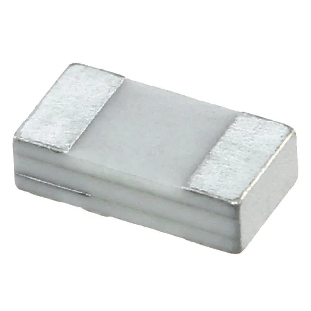
PKGS-00LDP1-R

PKGS-00LDP1-R

  • 厂商:

    MURATA-PS(村田)

  • 封装:

    SEN_6.4X2.8MM_SM

  • 描述:

    PKGS-00LDP1-R

  • 详情介绍
  • 数据手册
  • 价格&库存
PKGS-00LDP1-R 数据手册
Reference only Product Specification for Reference Only Issued Date: Jun. 05, 2013 Rev. : 2 Part Description: SHOCK SENSOR MURATA Part No.: PKGS-00LDP1-R The product specification in this sheet is for reference only. The contents of this specification are subject to change. You are requested to receive the latest specification and to return one copy of the specification to us with your receipt signature before going into mass production. Product engineering section Sensor Products Department Sensor Products Division Murata MFG. Co.,Ltd. Approved by Issued by Issued Date Drawing No. H. Kita T. Kawamoto Nov. 1, 2010 Reference only P.1 /15 Reference only P.2 /15 SPECIFICATION for TRANSDUCER Part Number: PKGS-00LDP1-R 1. Scope This product specification is applied to surface mountable acceleration sensors used for hard disk drive in a personal computer. Please contact us before using any of the products in the applications not described above. 2. Part Number 2-1 Murata Part Number :PKGS-00LDP1-R 2-2 Customer Part Number : 2-3 Customer Drawing Number : 3. Outline Drawing and Dimensions 3-1 Appearance 3-2 Dimensions 3-3 Construction : As per paragraph 10.Appearance criteria. : See Figure 2. : A piezo ceramic element is stuck between two ceramic substrate. 4. Characteristics (∗ Temperature 25±3°C, unless otherwise noted) Parameter Test Condition Min. Typ. Max. Units Note 85.7 {0.840} +15% fC/(m/s2) {pC/G} 1,2,5 4-1 Electric Charge Sensitivity 1kHz, 98.1m/s2(10G) applied in the direction of D axis at Fig.1 -15% 4-2 Insulation Resistance 4-3 Non-Linearity 10V DC, after 1 min. 500 4-4 Resonance Frequency 4-5 Inclined Angle of Sensitivity Axis 4-6 Electric Charge Sensitivity Temperature Drift 4-7 Capacitance Ref. Voltage Sensitivity % of the Full-Scale output at 490 m/s2(50G). Range : ±50G Maximum deviation from initial value at +25°C. Maximum deviation Ta:70°C from initial value at Ta:0°C +25°C 1Vrms,1kHz 1kHz, 98.1m/s2(10G) applied in the direction of D axis at Fig.1 10000 1% MΩ 5% 17 20 -3 0 +3 0% +4% +10% -5% -2.5% 0% -30% 770 +30% {1.10} kHz Degree pF {mV/G} Note: 1. As measured with an applied acceleration in the direction of D at figure 1. In this case, positive voltage and electrical charge are generated at electrode B. 2. 1[G] = 9.80665 [m/s2] 3. Resonance frequency of inner bimorph element. 4. Input impedance of measurement circuit is 10 MΩ(Zi), and amplified gain is 0 dB. 5. f (femto)= 10-15 MURATA MANUFACTURING CO., LTD 3 1,2,4 Reference only P.3 /15 Z Y D 0±1° Electrode A X Polarity marking Electrode B Figure 1. Axis D : This axis is an acceleration applied direction, when electric charge sensitivity is checked. 5. Standard land pattern 2.8 Land pattern 2.0 3.4 2.0 Unit : mm 6. Absolute Rating Apply voltage between electrode A and B : 10 Vp-p within 60 sec. max. Storage temperature range : -40 to 85 °C Operating temperature range : -40 to 85 °C MURATA MANUFACTURING CO., LTD Reference only P.4 /15 7. Physical Characteristics Test Item Condition of Test Performance Requirements 7-1 Mechanical Shock The transducer shall be measured after being No visible damage and the applied three impacts in plus and minus measured values shall meet directions of three mutually perpendicular Table 2 planes. The shock is specified as 14700m/s2(1500G) half sine pulse of 0.5 ms duration. 7-2 Vibration The transducer shall be measured after being applied vibration of amplitude of 1.5 mm with 10 to 55 Hz band of vibration frequency to each of 3 perpendicular directions for 2 hours. ( 5 minutes × 24 cycles ) 7-3 Bend Strength The transducer is soldered onto the center of No visible damage and the PCB PCB (1.6 mm thickness) which is laid on the 2 measured values shall meet small supporters spaced 90 mm. Table 3 PCB is deflected to 1 mm below from horizontal level by the pressing force with 20 × 10. R10 stick. The force is supplied for 1 second, 5 times repeatably. Stick 20 10 Load PCB Deflection φ 5 Supporter Part 45 ±1 Off-Center 45 1 R10 Unit: mm 7-4 Resistance to The transducer shall be mounted on PCB, then No visible damage and the Reflow measured after being applied following reflow measured values shall meet Soldering conditions. Table 2 Pre-heating : 60 to 150 sec. at 150 to 180 °C Heating : Within 60 sec. at 200 °C (or more) Within 30 sec. at 250 °C (or more) Peak Temperature: Within 10 sec. at 260 °C Shock sensor should be tested 2 times of this test flow. PCB size : 115 × 80 × 0.8 mm After being placed at ambient conditions for 8 hours, the transducer shall be measured. 7-5 Solderability End terminals are immersed in rosin for 75% min. end terminals shall 5 seconds then immersed in soldering bath of be wet with solder. +230±5°C for 3±0.5 seconds. 7-6 Washability See Table 1 MURATA MANUFACTURING CO., LTD No visible damage and the measured values shall meet Table 2 Reference only P.5 /15 Table 1 Wash Cleaning Solvent Item Alcohol (Iso-propanol) Water (Tap water, Demineralized water) Cleaning Water Silicon Solution (Techno care FRW) (Cleanthrough 750H, Pine alpha 100S ) Temperature Difference: ΔT *1 ΔT
PKGS-00LDP1-R
物料型号:PKGS-00LDP1-R

器件简介:该产品规格适用于表面贴装式加速度传感器,用于个人电脑硬盘驱动器。在未描述的应用中使用任何产品前,请与我们联系。

引脚分配:文档中未明确列出具体的引脚分配,但提供了标准焊盘图案,暗示了引脚布局。

参数特性: - 电荷灵敏度:在D轴方向上1kHz, 98.1m/s²(10G)的电荷灵敏度,典型值为85.7fC/(m/s²) (0.840pC/G)。 - 绝缘电阻:10V DC下,1分钟后的绝缘电阻,典型值为10000MΩ。 - 非线性:在±50G范围内,490 m/s²(50G)的全量程输出的非线性,最大为5%。 - 共振频率:17 kHz至20 kHz。 - 灵敏度轴的倾斜角度:最大偏差为±3度。 - 电容:在1Vrms, 1kHz下,电容的典型值为770pF。

功能详解:文档中未提供详细的功能解释,但提到了传感器的构造,即压电陶瓷元件被粘附在两个陶瓷基板之间。

应用信息:PKGS型冲击传感器专为硬盘驱动器应用设计,用于个人电脑和消费类音视频设备。在其他需要特别高可靠性的应用中使用此产品前,请联系Murata。

封装信息:封装的尺寸和标记在文档中有详细描述,但没有提供封装类型的具体名称或类型代码。

PKGS-00LDP1-R 价格&库存

很抱歉,暂时无法提供与“PKGS-00LDP1-R”相匹配的价格&库存,您可以联系我们找货

免费人工找货
PKGS-00LDP1-R
  •  国内价格
  • 1+13.77000
  • 10+13.48920
  • 30+13.29480
  • 100+13.11120

库存:0