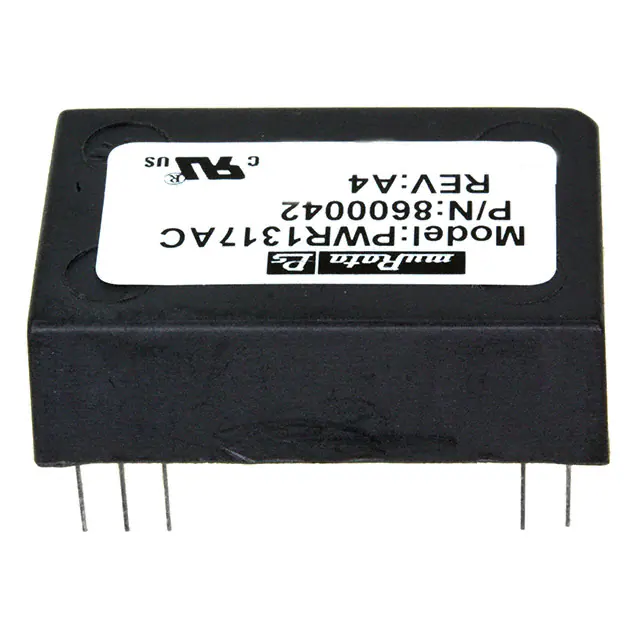
PWR13xxC
www.murata-ps.com
1.5 Watts Unregulated DC/DC Converters
FEATURES
■■
ROHS COMPLIANT
■■
HIGH ISOLATION - 4000V RATING
■■
8000V ISOLATION TEST VOLTAGE
■■
BARRIER 100% PRODUCTION TESTED
■■
LOW BARRIER CAPACITANCE - 10pF
■■
LOW LEAKAGE CURRENT - 2μA MAX
■■
24-PIN DIP PACKAGE
■■
INTERNAL FILTERING
APPLICATIONS
■■
BIOMEDICAL DATA ACQUISITION
■■
INDUSTRIAL PROCESS CONTROL
■■
ANALYTICAL MEASUREMENTS
■■
GROUND LOOP ELIMINATION
■■
INTRINSIC SAFETY SYSTEMS
PRODUCT OVERVIEW
The PWR13XXC Series offers a broad line of
low-cost, high-isolation voltage, unregulated,
single and dual output DC/DC converters in a
24-pin DIP package. These small converters
offer a 4000V isolation rating in a 1.25" x
0.8" package area.
Reliability is further enhanced by the use of
MOSPOWER transistors. These rugged devices
permit higher frequency operation with less
complicated drive circuitry than is possible with
bipolar power transistors. Reduced parts count
adds to the reliability of the PWR13XXC Series.
The dielectric withstand characteristics of
each converter is tested in production to ensure
barrier integrity. During the development of the
PWR13XXC Series extensive testing was done
to verify that subjecting the barrier to as many
as ten barrier tests will not destroy the barrier.
The high efficiency of the PWR13XXC Series
means less internal power dissipation. With
less heat to dissipate, the PWR13XXC Series
can operate over a wider ambient temperature
range with no degradation of reliable operation.
The PWR13XXC Series uses advanced circuit
design and packaging technology to realize
superior reliability and performance. A 220kHz
driven push-pull oscillator is used to ensure
stable frequency and non-saturating operation
of the input stage. This means there are no
high peak voltages or currents like other design
topologies, which can reduce unit reliability.
The PWR13XXC Series offers the user low
cost without sacrificing reliability. The use of
surface mounted devices and manufacturing
technologies make it possible to offer premium
performance and low cost. Testing of the
PWR13XXC isolation barrier is performed per
the methods set forth by UL544, VDE750, CSA
22.2 and IEC 601-1.
ISO 9001
For full details go to
www.murata-ps.com/rohs
CER TIFIED
www.murata-ps.com/support
MDC_PWR13xxC.C02 Page 1 of 4
�PWR13xxC
1.5 Watts Unregulated DC/DC Converters
ELECTRICAL SPECIFICATIONS
Specifications typical at TA = +25°C, nominal input voltage, rated output current unless otherwise noted.
INPUT CURRENT
NOMINAL RATED RATED
REFLECTED
INPUT VOLTAGE
OUTPUT VOLTAGE OUTPUT CURRENT
NO LOAD
RATED LOAD
RIPPLE CURRENT
MODEL (VDC) (VDC) (mA) (mA) (mA)
(mAp-p)
PWR1300AC
PWR1301AC
PWR1302AC
PWR1303AC
PWR1304AC
PWR1305AC
5
5
300
5 12 125
5 15 100
5
± 5
±150
5 ±12 ±63
5 ±15 ±50
50
400
30
50 400 30
50 400 30
50
400
30
50 400 30
50 400 30
PWR1306AC
12
5
300
PWR1307AC 12 12 125
PWR1308AC 12 15 100
PWR1309AC
12
± 5
±150
PWR1310AC
12
±12
±63
PWR1311AC 12 ±15 ±50
30
167
25
30 167 25
30 167 25
30
167
25
30
167
25
30 167 25
PWR1312AC
15
5
300
PWR1313AC 15 12 125
PWR1314AC 15 15 100
PWR1315AC
15
± 5
±150
PWR1316AC 15 ±12 ±63
PWR1317AC 15 ±15 ±50
30
133
20
30 133 20
30 133 20
30
133
20
30 133 20
30 133 20
COMMON SPECIFICATIONS
Specifications typical at TA = +25°C, rated input voltage, rated output current unless otherwise noted.
PARAMETER
CONDITIONS
INPUT
Voltage Range
MIN
4.5
10.8
13.5
TYP
5
12
15
MAX
UNITS
5.5
13.2
16.5
VDC
VDC
VDC
ISOLATION
Rated Voltage
4,000
Test Voltage
60 Hz, 60 Seconds
8,000
Resistance
10
Capacitance
10
Leakage Current
VISO= 240VAC, 60Hz
1
2
VDC
Vpk
GW
pF
µArms
OUTPUT
Rated Power
1.5
Voltage Setpoint Accuracy
Rated Load, Nominal Vin
±5
Ripple & Noise
BW = DC to 10MHz
40
BW = 10Hz to 2MHz
10
Watts
%
mVp-p
mVrms
REGULATION
Line Regulation
Load Regulation
High Line to Low Line
1.5
See Performance Curves
GENERAL
Efficiency
Switching Frequency
Package Weight
MTTF per MIL-HDBK-217, Rev. E
Circuit Stress Method
Ground Benign
TA = +25°C
TA = +85°C
Fixed Ground
TA = +35°C
Naval Sheltered
TA = +35°C
Airborne Uninhabited Fighter
TA = +35°C
TEMPERATURE
Specification
Storage
75
220
12
2,000,000
90,000
540,000
300,000
55,000
-40
+25
-55
+85
+110
%/%
%
kHz
g
Hr
Hr
Hr
Hr
Hr
°C
°C
www.murata-ps.com/support
MDC_PWR13xxC.C02 Page 2 of 4
�PWR13xxC
1.5 Watts Unregulated DC/DC Converters
ORDERING INFORMATION
ABSOLUTE MAXIMUM RATINGS
Output Short-Circuit Duration...................................................... 5 seconds
Internal Power Dissipation............................................................... 750mW
Lead Temperature (soldering, 10 seconds max)..............................+300°C
PWR
13XX A
C
Device Family
PWR indicates DC/DC converter
Model Number
Selected from Table of Electrical Characteristics
Package
RoHS Compliant
MECHANICAL
TOP VIEW
.805±0.010"
(20.45)
PIN CONNECTIONS
1.270±0.010"
(32.26)
SIDE VIEW
0.400±0.010"
(10.16)
.010±0.005"
(0.25)
0.100±0.015"
(2.54)
.020±0.002"
(0.51)
0.170" MIN
(4.32)
PIN
SINGLE MODELS
DUAL MODELS
1
+VIN +VIN
2
+VIN +VIN
11
+VOUT +VOUT
12
+VOUT +VOUT
13
-V OUT Common
14
-V OUT Common
15 No Pin -VOUT
23
-VIN -VIN
24
-VIN -VIN
Notes:
All dimensions are in inches (millimeters).
GRID: 0.100 inches (2.54 millimeters)
* Common pins not present on single output models.
BOTTOM VIEW
PIN PLACEMENT TOLERANCE: ± 0.015"
11 12
Marked with: specific model ordered, date code, job code.
0.600"
(15.23)
1 2
24 23
15 14 13
.1025"
(.267)
MATERIAL: Units are encapsulated in a low thermal resistance
molding compound which has excellent chemical resistance, wide
operating temperature range, and good electrical properties under
high humidity environments. The encapsulant and outer shell of the
unit have UL94V-0 ratings. Lead material is matte tin 100 microinches
min., over nickel, 40-80 microinches.
SOLDERING INFORMATION
The PWR13XXC devices are intended for wave soldering or manual soldering.
They are not intended to be subject to surface mount processes under any circumstances.
The normal wave soldering process can be used with these devices where the device is subjected
to a maximum wave temperature of 260°C for a period of no more than 10 seconds. Within this time
and temperature range, the integrity of the device’s plastic body will not be compromised and internal
temperatures within the converter will not exceed 175°C. Care should be taken to control manual
soldering limits identical to that of wave soldering.
www.murata-ps.com/support
MDC_PWR13xxC.C02 Page 3 of 4
�PWR13xxC
1.5 Watts Unregulated DC/DC Converters
TYPICAL PERFORMANCE CURVES
Specifications at TA = +25°C, nominal input voltage, rated output current
VOUT VS LOAD
(12VOUT MODELS)
16.00
5.6
13.50
15.75
5.4
13.00
12.50
0
5.8
25%
50%
75%
12.0
100%
0
25%
50%
75%
Load (% of Rated)
Load (% of Rated)
VOUT VS LOAD
(±5VOUT MODELS)
VOUT VS LOAD
(±12VOUT MODELS)
14.00
5.6
100%
VOUT (VDC)
5.0
25%
50%
75%
13.00
100%
Load (% of Rated)
Murata Power Solutions, Inc.
11 Cabot Boulevard, Mansfield, MA 02048-1151 U.S.A.
ISO 9001 and 14001 REGISTERED
25%
50%
75%
100%
VOUT VS LOAD
(±15VOUT MODELS)
15.75
15.50
15.25
15.0
12.00
0
0
16.00
12.50
5.2
15.0
Load (% of Rated)
13.50
5.4
15.50
15.25
VOUT (VDC)
5.0
VOUT (VDC)
14.00
5.2
VOUT (VDC)
VOUT VS LOAD
(15VOUT MODELS)
5.8
VOUT (VDC)
VOUT (VDC)
VOUT VS LOAD
(5VOUT MODELS)
0
25%
50%
75%
Load (% of Rated)
100%
0
25%
50%
75%
100%
Load (% of Rated)
This product is subject to the following operating requirements
and the Life and Safety Critical Application Sales Policy:
Refer to: http://www.murata-ps.com/requirements/
Murata Power Solutions, Inc. makes no representation that the use of its products in the circuits described herein, or the use of other
technical information contained herein, will not infringe upon existing or future patent rights. The descriptions contained herein do not imply
the granting of licenses to make, use, or sell equipment constructed in accordance therewith. Specifications are subject to change without
notice. © 2017 Murata Power Solutions, Inc.
www.murata-ps.com/support
MDC_PWR13xxC.C02 Page 4 of 4
�
很抱歉,暂时无法提供与“PWR1317AC”相匹配的价格&库存,您可以联系我们找货
免费人工找货- 国内价格 香港价格
- 1+343.313171+44.54460
- 10+321.8887610+41.76480
- 102+298.72252102+38.75900