SCA121T Series
Data Sheet
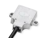
THE SCA121T DUAL AXIS INCLINOMETER MODULES
The SCA121T Series contain 3D-MEMS-based dual axis inclinometer modules that provide instrumentation grade
performance for leveling applications in harsh environment. The measuring axes of the sensing elements are
parallel to the mounting plane and orthogonal to each other. Low temperature dependency, high resolution and
low noise, together a with robust sensing element design, make the SCA121T the ideal choice for leveling
instruments. The Murata inclinometers are insensitive to vibration, due to their over damped sensing elements,
and can withstand mechanical shocks of up to 20000 g.
Features
•
•
•
•
•
•
•
Dual axis inclination measurement (X and Y)
Measuring ranges ±30° and ± 90°
0.0025° resolution (10 Hz BW, analog output)
Sensing element controlled over damped
frequency response (-3dB 18Hz)
Robust design, high shock durability (20000g)
High stability over temperature and time
Single +5 V supply and unregulated 7…35V
supply
•
RoHS compliant
•
•
Leveling instruments
Construction levels
Applications
•
•
Platform leveling and stabilization
360° vertical orientation measurement
Murata Electronics Oy
www.muratamems.fi
Subject to changes
Doc.Nr. 82 1274 00
1/5
Rev.A
�SCA121T Series
TABLE OF CONTENTS
The SCA121T Dual Axis Inclinometer modules .....................................................................1
Features............................................................................................................................................. 1
Applications ...................................................................................................................................... 1
Table of Contents......................................................................................................................2
1 Electrical Specifications .....................................................................................................3
1.1
Absolute Maximum Ratings ................................................................................................... 3
1.2
Performance Characteristics.................................................................................................. 3
1.3
Electrical Characteristics ....................................................................................................... 4
1.4
Electrical Connection.............................................................................................................. 4
2 Functional Description .......................................................................................................4
2.1
Measuring Directions .............................................................................................................. 4
2.2
Voltage to Angle Conversion ................................................................................................. 4
2.3
Ratiometric Output.................................................................................................................. 5
3 Mechanical Specifications ..................................................................................................5
3.1
Sensor dimensions ................................................................................................................. 5
Murata Electronics Oy
www.muratamems.fi
Subject to changes
Doc. nr. 82 1274 00
2/5
Rev.A
�SCA121T Series
1
Electrical Specifications
The SCA121T product family comprises three versions, the SCA121T-D03, the SCA121T-D05 and
the SCA121T-D07 that differs in measurement range and supply voltage. The product version
specific performance specifications are listed in the table SCA121T performance characteristics
below.
1.1
Absolute Maximum Ratings
Supply voltage SCA121T-D05(VDD)
Supply voltage SCA121T-D03 and D07
Voltage at input / output pins
Storage temperature
Operating temperature
Mechanical shock
1.2
Regulated -0.3 V to +5.5V
Unregulated -0.3 V to +35V
-0.3V to 5.3
-55°C to +125°C
-40°C to +125°C
Drop from 1 meter onto a concrete surface
(20000g). Powered or non-powered
Performance Characteristics
Parameter
Condition
Measuring range
Nominal
Supply Voltage
Offset (Output at 0g)
Offset calibration error
Sensitivity
Max deviation
between 0…1°
(1
Sensitivity calibration
error
Offset temperature
dependency
Typical non-linearity
Frequency response
-25…85°C
0…70°C
-25...85°C
0…70°C
Measuring range
(2
–3dB LP
Ratiometric error
Cross-axis sensitivity
Vdd = 4.75...5.25V
Max.
Sensitivity temperature
dependency
Note 1.
Note 2.
Murata Electronics Oy
www.muratamems.fi
SCA121TD03
±90
±1
7…35
2.5
±1.5
2
35
±1.5
SCA121T
-D05
±90
±1
5±0.25
Vdd/2
±1.5
2
35
±1.5
SCA121T
-D07
±30
±0.5
7…35
2.5
±1.5
4
70
±1.5
Units
±1
±0.5
-1.5...+0.5
-0.8...+0.3
±0.57
8-28
±1
±0.5
-1.5...+0.5
-0.8...+0.3
±0.57
8-28
±1
±0.5
-1.5...+0.5
-0.8...+0.3
±0.11
8-28
°
°
%
%
°
Hz
4
%
%
±1
4
°
g
V
V
°
V/g
mV/°
%
The angle output has SIN curve relationship to voltage output
The frequency response is determined by the sensing element’s internal gas damping.
Subject to changes
Doc. nr. 82 1274 00
3/5
Rev.A
�SCA121T Series
1.3
1.4
2
2.1
Electrical Characteristics
Parameter
Condition
Min.
Current consumption
Operating temperature
Analog resistive output load
Analog capacitive output load
Start-up delay
Vdd = 5 V; No load
Vout to Vdd or GND
Vout to Vdd or GND
Reset and parity check
-25
10
Typ
Max.
Units
5
8
+85
mA
°C
kOhm
nF
ms
20
10
Electrical Connection
Wire Color
Name
Function
Blue
Red
Yellow
Green
White
GND
Vdd
Out X
Out Y
NC
Ground
Power supply
X-axis output
Y-axis output
Not Connected
Functional Description
Measuring Directions
Figure 1. The measuring directions of the SCA121T
2.2
Voltage to Angle Conversion
Analog output can be transferred to angle using the following equation for conversion:
Vout − Offset
Sensitivity
α = arcsin
Where: Offset = output of the device at 0° inclination position, Sensitivity is the sensitivity of the
device and V Dout is the output of the SCA121T. The nominal offset is 2.5 V and the sensitivity is 4
V/g for the SCA121T-D07 and 2 V/g for the SCA121T-D03 and SCA121T-D05.
Angles close to 0° inclination can be estimated quite accurately with straight line conversion but for
the best possible accuracy, arcsine conversion is recommended to be used. The following table
shows the angle measurement error if straight line conversion is used.
Murata Electronics Oy
www.muratamems.fi
Subject to changes
Doc. nr. 82 1274 00
4/5
Rev.A
�SCA121T Series
Straight line conversion equation:
α=
Vout − Offset
Sensitivity
Where: Sensitivity = 70mV/° with SCA121T-D07 or Sensitivity= 35mV/° with SCA121T-D03 and
SCA121T-D05
Tilt angle [°]
0
1
2
3
4
5
10
15
30
2.3
Straight line conversion error [°]
0
0.0027
0.0058
0.0094
0.0140
0.0198
0.0787
0.2185
1.668
Ratiometric Output
Ratiometric output means that the zero offset point and sensitivity of the sensor are proportional to
the supply voltage. If the SCA121T-D05 supply voltage is fluctuating the SCA121T-D05 output will
also vary. When the same reference voltage for both the SCA121T-D05 sensor module and the
measuring part (A/D-converter) is used, the error caused by reference voltage variation is
automatically compensated for.
3
Mechanical Specifications
Cable length:
Cable type:
Cable diam.:
Leads:
Total weight:
Protection class:
Housing:
Mounting:
3.1
-D03,-D07
30cm
-D05
110cm
UL/CSA listed, PUR black
6±0.2mm
2
5 x 0.14mm
Approx. 60 grams
IP66
Zinc casting with passivation
The sensor module is to be mounted on a flat and smooth surface
with 2 screws, dimension M4. Mounting torque 5 ±1Nm
Sensor dimensions
Figure 2.
Murata Electronics Oy
www.muratamems.fi
Mechanical dimensions of the SCA121T (Dimensions in mm)
Subject to changes
Doc. nr. 82 1274 00
5/5
Rev.A
�
很抱歉,暂时无法提供与“SCA121T-D05”相匹配的价格&库存,您可以联系我们找货
免费人工找货