UWQ-12/17-Q48T-C Series
www.murata-ps.com
Wide Input, Isolated DOSA Quarter Brick
DC-DC Converters with Trim and Sense
PRODUCT OVERVIEW
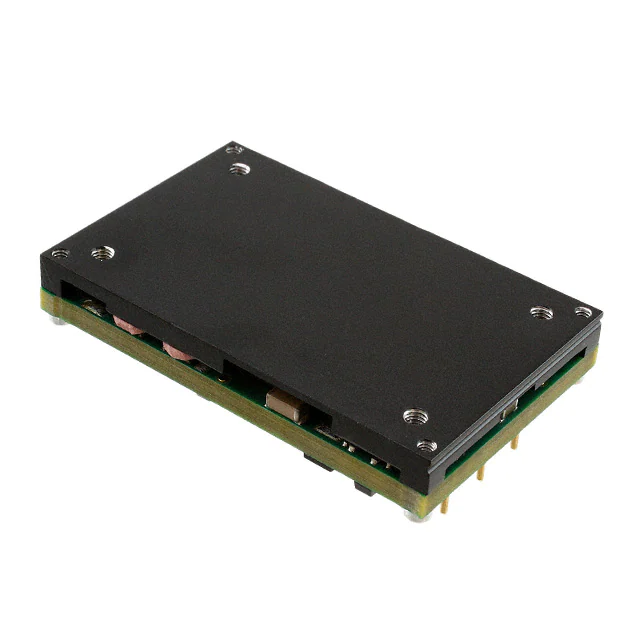
Typical
Typ
ical units
FEATURES
S
Fixed DC output, 12V @17A (204W)
Industry standard quarter brick 2.3˝ x 1.45˝ x
0.46˝ (58.4 x 36.8 x 11.7mm) package without
baseplate (0.5˝ [12.7mm] with baseplate)
Wide range Vin 18 to 75 Vdc
Trimmable 10.8Vout to 13.2Vout @ 210W max.
2250 Volt Basic isolation
Remote ON/Off enable control
Th UWQ-12/17-Q48T series offers high output
The
current (up to 17 Amps) in an industry standard
cu
“quarter brick” package requiring no heat sink
“q
for most applications. The UWQ-12/17-Q48T is
fo
trimmable from 10.8Vout to 13.2Vout and includes
tri
output sense pins to compensate for output voltage
ou
inaccuracy delivered at the load. The UWQ-12/17ina
Q48T series delivers fixed DC output voltages up
Q4
to 204 Watts (12V @17A) for printed circuit board
mounting. Wide range inputs of 18 to 75 Volts DC
m
(48 Volts nominal) are ideal for wireless base stations, datacom, and telecom systems.
Advanced automated surface mount assembly,
thermal management technology, and planar
magnetics deliver high reliability galvanic isolation
rated at 2250 Vdc for basic insulation. To power
digital systems, the output delivers fast settling to
current steps and stable operation where higher
capacitive loads are required. Excellent ripple and
noise specifications deliver stable 12V BUS for
IBC applications. For systems needing controlled
startup/shutdown, an external remote On/Off control may use either positive or negative logic.
Several self-protection features include input undervoltage lockout, output overvoltage protection,
and overtemperature shutdown (using an on-board
temperature sensor); overcurrent protection using the “hiccup” autorestart technique provides
indefinite short-circuit protection. The synchronous
rectifier topology along with advanced thermal
management delivers high efficiency for minimal
heat generation and “no heat sink” operation.
The UWQ-12/17-Q48T series is certified to
safety standards UL/EN/IEC/CSA 60950-1, 2nd
edition. It meets Class B EMI conducted emission
compliance to EN55022, CISPR22 with an external
filter.
DOSA-compatible pinouts, with trim and sense
High efficiency synchronous rectifier topology
Stable no-load operation
Monotonic startup into pre-bias output condition
Certified to UL/EN 60950-1, CSA-C22.2 No.
60950-1, 2nd edition safety approvals
Extensive self-protection, OVP, input undervoltage, current limiting and thermal shutdown
F1
APPLICATIONS
Wireless base stations embedded systems,
datacom and telecom installations
Disk farms, data centers and cellular repeater sites
Remote sensor systems
Instrumentation systems, R&D platforms, automated test fixtures
Data concentrators, voice forwarding and
speech processing systems
+Vin (1)
+Vout (8)
Barrier
External
DC
Power
Source
On/Off
Control
(2)
Controller
and Power
Open = On
Reference and
Error Amplifier
Trim (6)
logic)
-Vin (3)
-Vout (4)
Figure 1. Connection Diagram
Typical topology is shown. Murata Power Solutions recommends an external fuse.
For full details go to
www.murata-ps.com/rohs
www.murata-ps.com/support
MDC_UWQ-12-17-Q48T-C.A01 Page 1 of 17
�UWQ-12/17-Q48T-C Series
Wide Input, Isolated DOSA Quarter Brick
DC-DC Converters with Trim and Sense
ORDERING GUIDE ➀
Output
Input
R/N (mV
IOUT
IIN full
pk-pk) Regulation (Max.) ➁
VOUT (Amps, Power
VIN Nom. Range
IIN no
load
(Volts) max.) (Watts) Typ. Max.
Line
Load
(Volts) (Volts) load (mA) (Amps)
Root Model ➀
UWQ-12/17-Q48T-C ➁
12
17
204
100
120
±0.25%
±0.3%
48
➀ Please refer to the part number structure for additional ordering information and options.
➁ All specifications are typical at nominal line voltage and full load, +25°C unless otherwise noted. See
18-75
80
4.62
Efficiency
Dimensions
Min.
Typ.
(inches)
90%
92% 2.30x1.45x0.46 max. 58.4x36.8x11.7
(mm)
detailed specifications. Output capacitors are 1 μF || 10 μF with a 22μF input capacitor. These caps are
necessary for our test equipment and may not be needed for your application.
PART NUMBER STRUCTURE
UWQ - 12 / 17 - Q48 N T
B 9 Lx - C
RoHS Hazardous Materials compliance
C = RoHS-6 (does not claim EU RoHS exemption 7b–lead in solder), standard
Family
Series:
Wide Input
Quarter Brick
Pin length option
Blank = standard pin length 0.188 in. (4.78 mm)
L1 = 0.110 in. (2.79 mm)*
Nominal Output Voltage
L2 = 0.145 in. (3.68 mm)*
*Special quantity order is required;
no sample quantities available.
Maximum Rated Output :
Current in Amps
Baseplate Connect Pin 9 (special order)*
Blank = No pin 9, standard
9 = Pin 9 installed, connects to baseplate
Input Voltage Range:
Q48 = 18-75 Volts (48V nominal)
On/Off Control Logic
N = Negative logic
P = Positive logic
Baseplate Option
Blank = No baseplate, standard
B = Baseplate installed, optional
Trim & Sense
T = Trim & Sense pins included**
Note:
Some model number combinations
may not be available. Please contact
Murata Power Solutions.
**If Trim & Sense pins are not
required, please click here for the UWQ
http://www.murata-ps.com/data/power/uwq.pdf
series (UWQ-12/17-Q48) data sheet, or
contact Murata Power Solutions.
UWQ Pin 9 Baseplate Connection
The UWQ module has an additional pin 9 on special order that connects to the baseplate but is
electrically isolated from the rest of the converter. Please refer to the mechanical drawings.
Pin 9 offers a positive method of controlling the electrical potential of the baseplate, independent of the converter.
The baseplate may be ordered by adding a “B” to the model number tree and pin 9 will be preinstalled by adding a “9.” The two options are separate. Please refer to the Ordering Guide. Do
not order pin 9 without the baseplate. Note that “pin 9” converters may be on limited forecast,
requiring minimum order quantities and scheduled deliveries.
UWQ-12/17-Q48NTBL1-C
Complete Model Number Example:
Negative On/Off logic, trim & sense included, baseplate installed, 0.110˝ pin length, RoHS-6 compliance
www.murata-ps.com/support
MDC_UWQ-12-17-Q48T-C.A01 Page 2 of 17
�UWQ-12/17-Q48T-C Series
Wide Input, Isolated DOSA Quarter Brick
DC-DC Converters with Trim and Sense
FUNCTIONAL SPECIFICATIONS
Conditions/Comments ➀
ABSOLUTE MAXIMUM RATINGS
Input Voltage, Continuous
Full power operation
Operating or non-operating,
100 mS max. duration
Input to output
Power on or off, referred to -Vin
Input Voltage, Transient
Isolation Voltage
On/Off Remote Control
Output Power
Minimum
18
Typical/Nominal
48
0
0
Maximum
Units
80
Vdc
100
Vdc
2250
13.5
210.12
Vdc
Vdc
W
Current-limited, no damage,
0
17
A
short-circuit protected
Storage Temperature Range
Vin = Zero (no power)
-55
125
°C
Absolute maximums are stress ratings. Exposure of devices to greater than any of these conditions may adversely affect long-term reliability. Proper operation under conditions other than those
listed in the Performance/Functional Specifications Table is not implied or recommended.
Output Current
Conditions/Comments ➀ ➂
INPUT
Operating voltage range
Recommended External Fuse
Start-up threshold, measured at 50% load
Undervoltage shutdown, measured at 50% load
Overvoltage protection
Internal Filter Type
Input current
Full Load Conditions
Low Line
Inrush Transient
Short Circuit Input Current
No Load input current
Shut down mode input current
Reflected (back) ripple current ➁
Back Ripple Current, No Filtering
Back Ripple Current, with 22μf external
input capacitor
18
Fast blow
Rising input voltage
Falling input voltage
N/A
L-C
16.5
15
Vin = nominal
Vin = minimum
Vin = 48V.
Iout = minimum, unit=ON
Measured at input with specified filter
48
20
17.5
16
75
17.9
17
Vdc
A
Vdc
Vdc
4.52
12.06
0.05
50
80
5
15
500
4.76
12.69
0.1
100
150
6.5
25
525
A
A
A2-Sec.
mA
mA
mA
mA, RMS
mA-p-p
300
400
mA-p-p
GENERAL and SAFETY
Efficiency
Isolation
Isolation Voltage, input to output
Isolation Voltage, input to baseplate
Isolation Voltage, output to baseplate
Insulation Safety Rating
Isolation Resistance
Isolation Capacitance
Safety (certified to the following
requirements)
Calculated MTBF
Vin=48V, full load
90
With or without baseplate
With baseplate
With baseplate
Basic
2250
1500
1500
92
%
Vdc
Vdc
Vdc
100
1500
UL-60950-1, CSA-C22.2 No.60950-1,
IEC/EN60950-1, 2nd edition
Per Telcordia SR-332, issue 1, class 3, ground
fixed, Tambient=+25°C
MΩ
pF
Yes
Hours x 103
TBC
DYNAMIC CHARACTERISTICS
Fixed Switching Frequency
250
Power On, to Vout regulation band,
100% resistive load
Remote ON to Vout Regulated
50-75-50% load step to 3% of Vout
same as above
Startup Time
Startup Time
Dynamic Load Response
Dynamic Load Peak Deviation
275
300
KHz
60
65
mS
60
220
±500
65
275
±700
mS
μSec
mV
1
Vdc
13.5
Vdc
2
mA
13.5
V
FEATURES and OPTIONS
Remote On/Off Control ➃
“N” suffix:
Negative Logic, ON state
Negative Logic, OFF state
Control Current
“P” suffix:
Positive Logic, ON state
Positive Logic, OFF state
Control Current
Base Plate
ON = Pin connected to -Vin or to external source
OFF = Pin open or connected to external voltage
source
Open collector/drain
ON = Pin open or connected to external voltage
source
OFF = Pin connected to -Vin or to external
voltage
Open collector/drain
"B" suffix
0
3.5
1
3.5
0
1
1
V
2
mA
www.murata-ps.com/support
MDC_UWQ-12-17-Q48T-C.A01 Page 3 of 17
�UWQ-12/17-Q48T-C Series
Wide Input, Isolated DOSA Quarter Brick
DC-DC Converters with Trim and Sense
FUNCTIONAL SPECIFICATIONS, (CONT.)
Conditions/Comments ➀
OUTPUT
Total Output Power
Voltage
Setting Accuracy, fixed output
Output Voltage Range
Overvoltage Protection
Current
Output Current Range
Minimum Load
Current Limit Inception
Short Circuit
Short Circuit Current
Short Circuit Duration
(remove short for recovery)
Short circuit protection method
Regulation ➄
Line Regulation
Load Regulation
Ripple and Noise ➅
Temperature Coefficient
Maximum Capacitive Loading
Remote Sense Compliance
At 50% load, not user adjustable
User-adjustable
Via magnetic feedback
No minimum load
97% of Vnom., cold condition
Minimum
Maximum
Units
204
210
W
11.64
-10
12
12.36
+10
15
Vdc
% of Vnom.
Vdc
0.0
17
17
A
17.5
19.5
21.5
A
5
6
A
±0.25
±0.3
% of Vout
% of Vout
120
mV pk-pk
10
% of Vout./°C
μF
% of Vout
Hiccup technique, autorecovery within 1.25%
of Vout
Output shorted to -Vout, no damage.
Continuous operation
Hiccup technique-auto recovery
Vin=min. to max., Vout=nom., full load
Iout=min. to max., Vin=nom.
5 Hz- 20 MHz BW, Cout=1μF MLCC paralleled
with 10μF tantalum
At all outputs
Low ESR caps
Sense connected at load
Typical/Nominal
0.0
100
0
0.02
5000
MECHANICAL (Through Hole Models)
Outline Dimensions (open frame)
Outline Dimensions (with baseplate)
Weight
With baseplate
With baseplate
Without baseplate
Without baseplate
Through Hole Pin Diameter
Through Hole Pin Material
TH Pin Plating Metal and Thickness
Baseplate Material
Copper alloy
Nickel subplate
Gold overplate
Aluminum
2.3x1.45x0.46
58.4x36.8x11.7
2.3x1.45x0.5
58.4x36.8x12.7
2.12
60.19
1.6
45.36
0.04 & 0.06
1.016 & 1.52
Inches
mm
Inches
mm
Ounces
Grams
Ounces
Grams
Inches
mm
50
5
μ-inches
μ-inches
ENVIRONMENTAL
Operating Ambient Temperature Range
Operating Case Temperature
Storage Temperature
Thermal Protection/Shutdown
Electromagnetic Interference
Conducted, EN55022/CISPR22
RoHS rating
Notes
See derating curves
With baseplate, no derating
Vin = Zero (no power)
Measured in center
External filter is required
Class B with external filter
RoHS-6
➀ Unless otherwise noted, all specifications apply at Vin = nominal, nominal output voltage and full
output load. General conditions are near sea level altitude, no base plate installed and natural
convection airflow unless otherwise specified. All models are tested and specified with external
parallel 1 μF and 10 μF multi-layer output capacitors and a 22μf external input capacitor (see
Technical Notes). All capacitors are low-ESR types wired close to the converter. These capacitors
are necessary for our test equipment and may not be needed in the user’s application.
➁ Input (back) ripple current is tested and specified over 5 Hz to 20 MHz bandwidth. Input filtering is
Cin = 33 μF/100V, Cbus = 220μF/100V and Lbus = 12 μH.
-40
-40
-55
115
125
85
110
125
130
°C
°C
°C
°C
➂ All models are stable and regulate to specification under no load.
➃ The Remote On/Off Control is referred to -Vin.
➄ Regulation specifications describe the output voltage changes as the line voltage or load current
is varied from its nominal or midpoint value to either extreme. The load step is ±25% of full load
current.
➅ Output Ripple and Noise is measured with Cout = 1μF paralleled with 10μF, 20 MHz oscilloscope
bandwidth and full resistive load.
www.murata-ps.com/support
MDC_UWQ-12-17-Q48T-C.A01 Page 4 of 17
�UWQ-12/17-Q48T-C Series
Wide Input, Isolated DOSA Quarter Brick
DC-DC Converters with Trim and Sense
TYPICAL PERFORMANCE DATA
Efficiency vs. Line Voltage and Load Current @ 25°C
Power Dissipation @ 25°C
30
95
20
VIN = 18V
VIN = 24V
VIN = 36V
VIN = 48V
VIN = 60V
VIN = 75V
85
80
75
Watts
Efficiency (%)
VIN = 18V
VIN = 24V
VIN = 36V
VIN = 48V
VIN = 60V
VIN = 75V
25
90
15
10
5
0
70
1
2
3
4
5
6
7
8
65
1
2
3
4
5
6
7
8
9
9 10 11 12 13 14 15 16 17
Amps
10 11 12 13 14 15 16 17
Load Current (Amps)
18
17
16
15
14
13
12
11
10
9
8
7
6
5
Maximum Current Temperature Derating at Sea Level
(Vin= 36V, airflow from pin 1 to pin 3, with baseplate)
Output Current (Amps)
Output Current (Amps)
Maximum Current Temperature Derating at Sea Level
(Vin= 24V, airflow from pin 1 to pin 3, with baseplate)
Natural Convection
0.5 m/s (100 LFM)
1.0 m/s (200 LFM)
1.5 m/s (300 LFM)
2.0 m/s (400 LFM)
30
35
40
45
50
55
60
65
Ambient Temperature (°C)
70
75
80
85
18
17
16
15
14
13
12
11
10
9
8
7
6
5
4
3
2
1
0
30
18
17
16
15
14
13
12
11
10
9
8
7
6
5
4
3
2
1
0
30
Natural Convection
0.5 m/s (100 LFM)
1.0 m/s (200 LFM)
1.5 m/s (300 LFM)
2.0 m/s (400 LFM)
35
40
45
50
55
60
65
Ambient Temperature (°C)
70
75
35
40
45
50
55
60
65
Ambient Temperature (°C)
70
75
80
85
80
85
Maximum Current Temperature Derating at Sea Level
(Vin= 60V, airflow from pin 1 to pin 3, with baseplate)
Output Current (Amps)
Output Current (Amps)
Maximum Current Temperature Derating at Sea Level
(Vin= 48V, airflow from pin 1 to pin 3, with baseplate)
Natural Convection
0.5 m/s (100 LFM)
1.0 m/s (200 LFM)
1.5 m/s (300 LFM)
2.0 m/s (400 LFM)
80
85
18
17
16
15
14
13
12
11
10
9
8
7
6
5
4
3
2
1
0
30
Natural Convection
0.5 m/s (100 LFM)
1.0 m/s (200 LFM)
1.5 m/s (300 LFM)
2.0 m/s (400 LFM)
35
40
45
50
55
60
65
Ambient Temperature (°C)
70
75
www.murata-ps.com/support
MDC_UWQ-12-17-Q48T-C.A01 Page 5 of 17
�UWQ-12/17-Q48T-C Series
Wide Input, Isolated DOSA Quarter Brick
DC-DC Converters with Trim and Sense
TYPICAL PERFORMANCE DATA
18
17
16
15
14
13
12
11
10
9
8
7
6
5
Maximum Current Temperature Derating at Sea Level
(Vin= 36V, airflow from pin 1 to pin 3, without baseplate)
Output Current (Amps)
Output Current (Amps)
Maximum Current Temperature Derating at Sea Level
(Vin= 24V, airflow from pin 1 to pin 3, without baseplate)
Natural Convection
0.5 m/s (100 LFM)
1.0 m/s (200 LFM)
1.5 m/s (300 LFM)
2.0 m/s (400 LFM)
30
35
40
45
50
55
60
65
Ambient Temperature (°C)
70
75
80
85
18
17
16
15
14
13
12
11
10
9
8
7
6
5
4
3
2
1
0
30
18
17
16
15
14
13
12
11
10
9
8
7
6
5
4
3
2
1
0
30
Natural Convection
0.5 m/s (100 LFM)
1.0 m/s (200 LFM)
1.5 m/s (300 LFM)
2.0 m/s (400 LFM)
35
40
45
50
55
60
65
Ambient Temperature (°C)
70
75
35
40
45
50
55
60
65
Ambient Temperature (°C)
70
75
80
85
80
85
Maximum Current Temperature Derating at Sea Level
(Vin= 60V, airflow from pin 1 to pin 3, without baseplate)
Output Current (Amps)
Output Current (Amps)
Maximum Current Temperature Derating at Sea Level
(Vin= 48V, airflow from pin 1 to pin 3, without baseplate)
Natural Convection
0.5 m/s (100 LFM)
1.0 m/s (200 LFM)
1.5 m/s (300 LFM)
2.0 m/s (400 LFM)
80
85
18
17
16
15
14
13
12
11
10
9
8
7
6
5
4
3
2
1
0
30
Natural Convection
0.5 m/s (100 LFM)
1.0 m/s (200 LFM)
1.5 m/s (300 LFM)
2.0 m/s (400 LFM)
35
40
45
50
55
60
65
Ambient Temperature (°C)
70
75
www.murata-ps.com/support
MDC_UWQ-12-17-Q48T-C.A01 Page 6 of 17
�UWQ-12/17-Q48T-C Series
Wide Input, Isolated DOSA Quarter Brick
DC-DC Converters with Trim and Sense
TYPICAL PERFORMANCE DATA
Start-up Delay (Vin=48V, Iout=17A, Ta=+25°C) Ch1=Vin, Ch2=Vout
Start-up Delay (Vin=48V, Iout=0A, Cload=5000μF, Ta=+25°C) Ch1=Vin, Ch2=Vout
Start-up Delay (Vin=48V, Iout=17A, Cload=5000μF, Ta=+25°C)
Ch1=Vin, Ch2=Vout
On/Off Enable delay (Vin=48V, Vout=nom, Iout=17A, Ta=+25°C)
Ch1=Enable, Ch2= Vout
On/Off Enable delay (Vin=48V, Vout=nom, Iout=0A, Cload=6000μF,
Ta=+25°C) Ch1=Enable, Ch2= Vout
On/Off Enable delay (Vin=48V, Vout=nom, Iout=17A, Cload=6000μF,
Ta=+25°C) Ch1=Enable, Ch2= Vout
www.murata-ps.com/support
MDC_UWQ-12-17-Q48T-C.A01 Page 7 of 17
�UWQ-12/17-Q48T-C Series
Wide Input, Isolated DOSA Quarter Brick
DC-DC Converters with Trim and Sense
TYPICAL PERFORMANCE DATA
Stepload Transient Response (Vin=48V, Iout=50-75-50% of Imax,
Cload=1μF || 10μF, Io=5A/div, Ta=+25°C) Ch2=Vout, Ch4=Iout
Stepload Transient Response (Vin=48V, Iout=50-75-50% of Imax,
Cload=6000μF, Io=5A/div, Ta=+25°C) Ch2=Vout, Ch4=Iout
Output Ripple & Noise (Vin=48V, Iout=0A, Cload=1μF || 10μF,
Ta=+25°C, BW=20MHz)
Output Ripple & Noise (Vin=48V, Iout=17A, Cload=1μF || 10μF,
Ta=+25°C, BW=20MHz)
Pre-biased Output Voltage Startup Operation (Vin=48Vdc, Iout=0A, Cout=5000uF,
Ta=+25°C) Ch1=Vin, Ch2=Vout.
Thermal image with hot spot at 9.22A with 25°C ambient temperature. Natural
convection is used with no forced airflow. Identifiable and recommended maximum
value to be verified in application.
www.murata-ps.com/support
MDC_UWQ-12-17-Q48T-C.A01 Page 8 of 17
�UWQ-12/17-Q48T-C Series
Wide Input, Isolated DOSA Quarter Brick
DC-DC Converters with Trim and Sense
MECHANICAL SPECIFICATIONS – OPEN FRAME
TOP VIEW
4.78
.188
(NOTE 1)
END VIEW
58.4
2.30
END VIEW
11.7
.46
36.8
1.45
1° MAX
(ALL PINS)
0.25
.010
MIN
BOTTOM
CLEARANCE
Mtg Plane
SIDE VIEW
.062 SHOULDER
(AT 40 MIL PINS)
MATERIAL:
.040 PINS: COPPER ALLOY
.062 PINS: COPPER ALLOY
1.57±0.05
.062±.002
@PINS 4 & 8
1.02±0.05
.040±.002
@PINS 1-3, 9
FINISH: (ALL PINS)
GOLD (5u"MIN) OVER NICKEL (50u" MIN)
2.000
REF
50.80
2.000
3.8
.15
3.81
.150
7.62
.300
1. ALTERNATE PIN LENGTHS AVAILABLE
(SEE PART NUMBER STRUCTURE)
2. COMPONENTS SHOWN ARE FOR REF ONLY
3. DIMENSIONS ARE IN INCHES [mm]
4. PIN LOCATION DIMENSIONS APPLY AT
CIRCUIT BOARD LEVEL
5. THESE CONVERTERS MEET THE MECHANICAL
SPECIFICATIONS OF A QUARTER BRICK DC-DC
CONVERTER
3
4
5
6
2
7
1
8
BOTTOM VIEW
(PIN SIDE)
INPUT/OUTPUT CONNECTIONS
Pin
Function
1
+Vin
2
Remote On/Off *
3
-Vin
4
-Vout
5
-Sense
6
Trim
7
+Sense
8
+Vout
9
No pin
*The Remote On/Off can be provided
with either positive (P suffix) or
negative (N suffix) logic.
7.62
.300
CL
3.81
.150
3.81
.150
Dimensions are in inches (mm shown for ref. only).
Third Angle Projection
Tolerances (unless otherwise specified):
.XX ± 0.02 (0.5)
.XXX ± 0.010 (0.25)
Angles ± 2˚
Components are shown for reference only
and may vary between units.
www.murata-ps.com/support
MDC_UWQ-12-17-Q48T-C.A01 Page 9 of 17
�UWQ-12/17-Q48T-C Series
Wide Input, Isolated DOSA Quarter Brick
DC-DC Converters with Trim and Sense
MECHANICAL SPECIFICATIONS – WITH BASEPLATE
TOP VIEW
END VIEW
12.2
0.48
47.24
1.860
4.78
0.188
36.8
1.45
1° MAX
(ALL PINS)
END VIEW
58.4
2.30
26.16
1.030
M3x0.5 x 0.10 MAX
PENETRATION (x4)
0.25
0.010
MIN
BOTTOM
CLEARANCE
Mtg Plane
SIDE VIEW
0.062 SHOULDER
(AT 40 MIL PINS)
MATERIAL:
0.040 PINS: COPPER ALLOY
0.062 PINS: COPPER ALLOY
1.02±0.05
0.040±0.002
@PINS 1-3, 9
FINISH: (ALL PINS)
GOLD (5u"MIN) OVER NICKEL (50u" MIN)
OPTIONAL PIN #9
CONNECTS TO BASEPLATE
AND IS ELECTRICALLY ISOLATED
FROM CONVERTER.
1.57±0.05
0.062±0.002
@PINS 4 & 8
2.000
REF
50.80
2.000
3.8
0.15
3.81
0.150
7.62
0.300
1. ALTERNATE PIN LENGTHS AVAILABLE
(SEE PART NUMBER STRUCTURE)
2. COMPONENTS SHOWN ARE FOR REF ONLY
3. DIMENSIONS ARE IN INCHES [mm]
4. PIN LOCATION DIMENSIONS APPLY AT
CIRCUIT BOARD LEVEL
5. THESE CONVERTERS MEET THE MECHANICAL
SPECIFICATIONS OF A QUARTER BRICK DC-DC
CONVERTER
3
9
4
5
6
2
7
8
1
BOTTOM VIEW
(PIN SIDE)
INPUT/OUTPUT CONNECTIONS
Pin
Function
1
+Vin
2
Remote On/Off *
3
-Vin
4
-Vout
5
-Sense
6
Trim
7
+Sense
8
+Vout
9
Baseplate (Optional)
*The Remote On/Off can be provided
with either positive (P suffix) or
negative (N suffix) logic.
7.62
0.300
CL
3.81
0.150
3.81
0.150
Dimensions are in inches (mm shown for ref. only).
Third Angle Projection
Tolerances (unless otherwise specified):
.XX ± 0.02 (0.5)
.XXX ± 0.010 (0.25)
Angles ± 2˚
Components are shown for reference only
and may vary between units.
www.murata-ps.com/support
MDC_UWQ-12-17-Q48T-C.A01 Page 10 of 17
�UWQ-12/17-Q48T-C Series
Wide Input, Isolated DOSA Quarter Brick
DC-DC Converters with Trim and Sense
MECHANICAL SPECIFICATIONS
RECOMMENDED FOOTPRINT
(VIEW THROUGH CONVERTER)
REF: DOSA STANDARD SPECIFICATION
FOR QUARTER BRICK DC/DC CONVERTERS
FINISHED HOLE SIZES
@ 1-3, 5-7, 9
TOP VIEW
(PER IPC-D-275, LEVEL C)
0.048-0.062
CL
(PRI)
(SEC)
1
2
CL
37.3
1.47
8
7
6
5
4
9 (When Applicable)
3.81
0.150
3
0.100 MIN
@ 1-3, 5-7, 9
FOR PIN
SHOULDERS
3.81
0.150
7.62
0.300
CL
7.62
0.300
FINISHED HOLE SIZES
@ PINS 4 & 8
25.4
1.00
(PER IPC-D-275, LEVEL C)
50.80
2.000
0.070-0.084
58.9
2.32
IT IS RECOMMENDED THAT NO PARTS
BE PLACED BENEATH CONVERTER
(HATCHED AREA)
Dimensions are in inches (mm shown for ref. only).
Third Angle Projection
Tolerances (unless otherwise specified):
.XX ± 0.02 (0.5)
.XXX ± 0.010 (0.25)
Angles ± 2˚
Components are shown for reference only
and may vary between units.
www.murata-ps.com/support
MDC_UWQ-12-17-Q48T-C.A01 Page 11 of 17
�UWQ-12/17-Q48T-C Series
Wide Input, Isolated DOSA Quarter Brick
DC-DC Converters with Trim and Sense
STANDARD PACKAGING
9.92
(251.97)
REF
9.92
(251.97)
REF
Each static dissipative polyethylene
foam tray accommodates
15 converters in a 3 x 5 array.
0.88 (22.35)
REF
2.75 (69.85) ±.25
closed height
11.00 (279.4) ±.25
10.50 (266.7) ±.25
Carton accommodates two (2) trays yielding 30 converters per carton
Dimensions are in inches (mm) shown for ref. only.
Third Angle Projection
Tolerances (unless otherwise specified):
.XX ± 0.02 (0.5)
.XXX ± 0.010 (0.25)
Angles ± 2˚
www.murata-ps.com/support
MDC_UWQ-12-17-Q48T-C.A01 Page 12 of 17
�UWQ-12/17-Q48T-C Series
Wide Input, Isolated DOSA Quarter Brick
DC-DC Converters with Trim and Sense
TECHNICAL NOTES
Input Fusing
Certain applications and/or safety agencies may require fuses at the inputs of
power conversion components. Fuses should also be used when there is the
possibility of sustained input voltage reversal which is not current-limited. For
greatest safety, we recommend a fast blow fuse installed in the +Vin supply
line.
The installer must observe all relevant safety standards and regulations. For
safety agency approvals, install the converter in compliance with the end-user
safety standard.
Input Under-Voltage Shutdown and Start-Up Threshold
Under normal start-up conditions, converters will not begin to regulate
properly until the rising input voltage exceeds and remains above the Start-Up
Threshold Voltage (see Specifications). Once operating, converters will not
turn off until the input voltage drops below the Under-Voltage Shutdown Limit.
Subsequent restart will not occur until the input voltage rises again above the
Start-Up Threshold. This built-in hysteresis prevents any unstable on/off operation at a single input voltage.
Threshold under all load conditions. Be sure to use adequate trace sizes and
mount components close to the converter.
I/O Filtering, Input Ripple Current and Output Noise
All models in this converter series are tested and specified for input reflected
ripple current and output noise using designated external input/output components, circuits and layout as shown in the figures below. External input capacitors (CIN in the figure) serve primarily as energy storage elements, minimizing
line voltage variations caused by transient IR drops in the input conductors.
Users should select input capacitors for bulk capacitance (at appropriate frequencies), low ESR and high RMS ripple current ratings. In the figure below, the
CBUS and LBUS components simulate a typical DC voltage bus. Specific system
configurations may require additional considerations. Please note that the values of CIN, LBUS and CBUS may vary according to the specific converter model.
TO
OSCILLOSCOPE
+VIN
VIN
Users should be aware however of input sources near the Under-Voltage Shutdown whose voltage decays as input current is consumed (such as capacitor
inputs), the converter shuts off and then restarts as the external capacitor recharges. Such situations could oscillate. To prevent this, make sure the operating
input voltage is well above the UV Shutdown voltage AT ALL TIMES.
Start-Up Delay
Assuming that the output current is set at the rated maximum, the Vin to Vout StartUp Delay (see Specifications) is the time interval between the point when the rising
input voltage crosses the Start-Up Threshold and the fully loaded regulated output
voltage enters and remains within its specified regulation band. Actual measured
times will vary with input source impedance, external input capacitance, input voltage slew rate and final value of the input voltage as it appears at the converter.
These converters include a soft start circuit to moderate the duty cycle of the
PWM controller at power up, thereby limiting the input and output inrush current.
The On/Off Remote Control interval from inception to VOUT regulated assumes
that the converter already has its input voltage stabilized above the Start-Up
Threshold before the On command. The interval is measured from the On command until the output enters and remains within its specified regulation band.
The specification assumes that the output is fully loaded at maximum rated
current.
Input Source Impedance
These converters will operate to specifications without external components,
assuming that the source voltage has very low impedance. Since real-world
voltage sources have finite minimum impedance, performance is improved
by adding external filter components. Sometimes only a small ceramic input
capacitor is sufficient. Since it is difficult to totally characterize all applications,
some experimentation may be needed. Note that external input capacitors
must accept high speed switching currents.
Performance will degrade with increasing input inductance. Excessive input
inductance may inhibit operation. The DC input regulation specifies that the
input voltage, once operating, must never degrade below the Shut-Down
CURRENT
PROBE
+
–
+
–
LBUS
CBUS
CIN
−VIN
CIN = 33μF, ESR < 200mΩ @ 100kHz
CBUS = 220μF, 100V
LBUS = 12μH
Figure 2. Measuring Input Ripple Current
In critical applications, output ripple and noise (also referred to as periodic and
random deviations or PARD) may be reduced by adding filter elements such as
multiple external capacitors. Be sure to calculate component temperature rise
from reflected AC current dissipated inside capacitor ESR. In order to minimize
circuit errors and standardize tests between units, scope measurements should
be made using BNC connectors or the probe ground should not exceed one half
inch and soldered directly to the fixture.
+VOUT
C1
C2
SCOPE
RLOAD
−VOUT
C1 = 1μF
C2 = 10μF
LOAD 2-3 INCHES (51-76mm) FROM MODULE
Figure 3. Measuring Output Ripple and Noise (PARD)
www.murata-ps.com/support
MDC_UWQ-12-17-Q48T-C.A01 Page 13 of 17
�UWQ-12/17-Q48T-C Series
Wide Input, Isolated DOSA Quarter Brick
DC-DC Converters with Trim and Sense
Floating Outputs
Since these are isolated DC-DC converters, their outputs are “floating” with
respect to their input. The essential feature of such isolation is ideal ZERO
CURRENT FLOW between input and output. Real-world converters however
do exhibit tiny leakage currents between input and output. These leakages
consist of both an AC stray capacitance coupling component and a DC leakage
resistance. When using the isolation feature, do not allow the isolation voltage
to exceed specifications. Otherwise the converter may be damaged. Designers
will normally use the negative output (-Output) as the ground return of the load
circuit. You can however use the positive output (+Output) as the ground return
to effectively reverse the output polarity.
Minimum Output Loading Requirements
These converters employ a synchronous rectifier design topology. All models
regulate within specification and are stable under no load to full load conditions.
Operation under no load might however slightly increase output ripple and noise.
Thermal Shutdown
To protect against thermal over-stress, these converters include thermal shutdown circuitry. If environmental or application conditions cause the temperature of the DC-DC’s to rise above the Operating Temperature Range up to the
shutdown temperature, an on-board electronic temperature sensor will power
down the unit. When the temperature decreases below the turn-on threshold,
the converter will automatically restart. There is a small amount of hysteresis
to prevent rapid on/off cycling. CAUTION: If the product is operated too close
to the thermal limits, it may shut down suddenly without warning. Be sure to
thoroughly test your application to avoid unplanned thermal shutdown.
Temperature Derating Curves
The graphs in this data sheet illustrate typical operation under a variety of conditions. The Derating curves show the maximum continuous ambient air temperature
and decreasing maximum output current which is acceptable under increasing
forced airflow measured in Linear Feet per Minute (“LFM”) or meters per second
(M/S). Note that these are AVERAGE, steady state measurements. The converter will
accept brief increases in temperature and/or current or reduced airflow as long as
the average is not exceeded.
Note that the temperatures are of the ambient airflow, not the converter itself
which is obviously running at higher temperature than the outside air. Also note
that “natural convection” is defined as very low flow rates which are not using
fan-forced airflow. Depending on the application, “natural convection” is usually about 30-65 LFM but is not equal to still air (0 LFM).
Murata Power Solutions makes Characterization measurements in a closed
cycle wind tunnel with calibrated airflow. Both thermocouples and an infrared
camera system are used to observe thermal performance.
CAUTION: If these Derating guidelines are exceeded, the converter may have
an unplanned Over Temperature shut down. Also, these graphs are all collected
near Sea Level altitude. Be sure to reduce the derating for higher altitude.
Output Overvoltage Protection (OVP)
This converter monitors its output voltage for an over-voltage condition using
magnetic feedback circuitry. If the output exceeds OVP limits, the sensing
circuit will power down the unit, and the output voltage will decrease. After
a time-out period, the PWM will automatically attempt to restart, causing the
output voltage to ramp up to its rated value. It is not necessary to power down
and reset the converter for this automatic OVP-recovery restart.
If the fault condition persists and the output voltage climbs to excessive levels,
the OVP circuitry will initiate another shutdown cycle. This on/off cycling is
referred to as “hiccup” mode.
Output Fusing
The converter is extensively protected against current, voltage and temperature
extremes. However, your application circuit may need additional protection. In the
extremely unlikely event of output circuit failure, excessive voltage could be applied
to the application circuit. Consider using an appropriate external protection.
Current Limiting
As power demand increases on the output and enters the specified “limit
inception range” limiting circuitry activates in the DC-DC converter to limit/
restrict the maximum current or total power available. Once the current
reaches a certain range the output voltage will start to decrease while the
output current continues to increase, thereby maintaining constant power, until
a maximum peak current is reached and the converter enters a “hiccup” (on
off cycling) mode of operation until the load is reduced below the threshold
level, whereupon it will return to a normal mode of operation. Current limit
inception is defined as the point where the output voltage has decreased by a
pre-specified percentage (usually a 2% decrease from nominal).
Short Circuit Condition
The short circuit condition is an extension of the “Current Limiting” condition.
When the monitored peak current signal reaches a certain range, the PWM
controller’s outputs are shut off thereby turning the converter “off.” This is
followed by an extended time out period. This period can vary depending on
other conditions such as the input voltage level. Following this time out period,
the PWM controller will attempt to re-start the converter by initiating a “normal
start cycle” which includes softstart. If the “fault condition” persists, another
“hiccup” cycle is initiated. This “cycle” can and will continue indefinitely until
such time as the “fault condition” is removed, at which time the converter will
resume “normal operation.” Operating in the “hiccup” mode during a fault
condition is advantageous in that average input and output power levels are
held low preventing excessive internal increases in temperature.
Trimming Output Voltage
UWQ converters have a trim capability (pin 6) that enables users to adjust the
output voltage from +10% to –10% (refer to the trim equations in the table
below). Adjustments to the output voltage can be accomplished with a single
fixed resistor as shown in Figures 4 and 5. A single fixed resistor can increase
or decrease the output voltage depending on its connection. Resistors should
be located close to the converter and have TCR’s less than 100ppm/°C to
minimize sensitivity to changes in temperature. If the trim function is not used,
leave the trim pin open.
Standard UWQs have a “positive trim” where a single resistor connected from
the Trim pin (pin 6) to the +Sense (pin 7) will increase the output voltage. A
resistor connected from the Trim Pin (pin 6) to the –Sense (pin 5) will decrease
the output voltage.
Trim adjustments greater than the specified +10%/–10% can have an adverse
affect on the converter’s performance and are not recommended. Excessive
voltage differences between VOUT and Sense, in conjunction with trim adjustment of the output voltage, can cause the overvoltage protection circuitry to
activate (see Performance Specifications for overvoltage limits).
www.murata-ps.com/support
MDC_UWQ-12-17-Q48T-C.A01 Page 14 of 17
�UWQ-12/17-Q48T-C Series
Wide Input, Isolated DOSA Quarter Brick
DC-DC Converters with Trim and Sense
Temperature/power derating is based on maximum output current and voltage
at the converter’s output pins. Use of the trim and sense functions can cause
output voltages to increase, thereby increasing output power beyond the UWQ’s
specified rating, or cause output voltages to climb into the output overvoltage
region. Therefore:
Contact and PCB resistance
losses due to IR drops
+VOUT
+VIN
I OUT
+SENSE
(VOUT at pins) x (IOUT) rated output power
Sense Current
The Trim pin (pin 6) is a relatively high impedance node that can be susceptible
to noise pickup when connected to long conductors in noisy environments.
Trim Up*
RT UP (kΩ) =
ON/OFF
CONTROL
Trim Down*
49.6(VO – 1.226)
–10.2
VO – 12
RT DOWN (kΩ) =
60.45
TRIM
LOAD
Sense Return
−SENSE
I OUT Return
–10.2
12 – VO
–VIN
-VOUT
Contact and PCB resistance
losses due to IR drops
*Vo = Desirable output voltage in Volts
Figure 6. Remote Sense Circuit Configuration
+VIN
function is not used for remote regulation, the user should connect +Sense to
+Vout and –Sense to –Vout at the converter pins.
+VOUT
+SENSE
ON/OFF
CONTROL
TRIM
LOAD
RTRIM UP
–SENSE
–VIN
–VOUT
Figure 4. Trim Connections To Increase Output Voltages Using Fixed Resistors
+VIN
+VOUT
The remote Sense lines carry very little current. They are also capacitively
coupled to the output lines and therefore are in the feedback control loop to
regulate and stabilize the output. As such, they are not low impedance inputs
and must be treated with care in PC board layouts. Sense lines on the PCB
should run adjacent to DC signals, preferably Ground. In cables and discrete
wiring, use twisted pair, shielded tubing or similar techniques.
Any long, distributed wiring and/or significant inductance introduced into the
Sense control loop can adversely affect overall system stability. If in doubt, test
your applications by observing the converter’s output transient response during
step loads. There should not be any appreciable ringing or oscillation. You
may also adjust the output trim slightly to compensate for voltage loss in any
external filter elements. Do not exceed maximum power ratings.
+SENSE
ON/OFF
CONTROL
TRIM
LOAD
RTRIM DOWN
–SENSE
–VIN
–VOUT
Figure 5. Trim Connections To Decrease Output Voltages Using Fixed Resistors
Remote Sense Input
Use the Sense inputs with caution. Sense is normally connected at the load.
Sense inputs compensate for output voltage inaccuracy delivered at the load.
This is done by correcting IR voltage drops along the output wiring and the
current carrying capacity of PC board etch. This output drop (the difference
between Sense and Vout when measured at the converter) should not exceed
0.5V. Consider using heavier wire if this drop is excessive. Sense inputs also
improve the stability of the converter and load system by optimizing the control
loop phase margin.
Note: The Sense input and power Vout lines are internally connected through
low value resistors to their respective polarities so that the converter can
operate without external connection to the Sense. Nevertheless, if the Sense
Remote On/Off Control
On the input side, a remote On/Off Control can be specified with either positive
or negative logic as follows:
Models are on (enabled) when the On/Off is grounded or brought to within
a low voltage (see Specifications) with respect to –VIN. The device is off
(disabled) when the On/Off is left open or is pulled high to +13.5VDC Max. with
respect to –VIN.
Dynamic control of the On/Off function should be able to sink the specified
signal current when brought low and withstand specified voltage when brought
high. Be aware too that there is a finite time in milliseconds (see Specifications)
between the time of On/Off Control activation and stable, regulated output. This
time will vary slightly with output load type and current and input conditions.
There are two CAUTIONs for the On/Off Control:
CAUTION: While it is possible to control the On/Off with external logic if you
carefully observe the voltage levels, the preferred circuit is either an open
drain/open collector transistor or a relay (which can thereupon be controlled
by logic). The On/Off prefers to be set at approx. +13.5V (open pin) for the ON
state, assuming positive logic.
www.murata-ps.com/support
MDC_UWQ-12-17-Q48T-C.A01 Page 15 of 17
�UWQ-12/17-Q48T-C Series
Wide Input, Isolated DOSA Quarter Brick
DC-DC Converters with Trim and Sense
CAUTION: Do not apply voltages to the On/Off pin when there is no input power
voltage. Otherwise the converter may be permanently damaged.
Please observe Sense inputs tolerance to avoid improper operation:
[Vout(+) −Vout(-)] − [Sense(+) −Sense(-)] ≤ 10% of Vout
Output overvoltage protection is monitored at the output voltage pin, not the
Sense pin. Therefore excessive voltage differences between Vout and Sense
together with trim adjustment of the output can cause the overvoltage protection circuit to activate and shut down the output.
Power derating of the converter is based on the combination of maximum output
current and the highest output voltage. Therefore the designer must ensure:
Emissions Performance
Murata Power Solutions measures its products for radio frequency emissions
against the EN 55022 and CISPR 22 standards. Passive resistance loads are
employed and the output is set to the maximum voltage. If you set up your
own emissions testing, make sure the output load is rated at continuous power
while doing the tests.
The recommended external input and output capacitors (if required) are included. Please refer to the fundamental switching frequency. All of this information
is listed in the Product Specifications. An external discrete filter is installed and
the circuit diagram is shown below.
(Vout at pins) x (Iout) ≤ (Max. rated output power)
UWQ EMI 200W Test Card
48Vdc in, 12Vout, 17Amps
Resistive
Load
UUT
+VCC
V+
Black
C16
C8
C17
ON/OFF
CONTROL
C8
C8
C8
L3
C8
C8
C7
Vin +
Vout +
Vin -
Vout -
Resistive
Load
inside a
metal
container
L1
V-
-VIN
Figure 7. Driving the On/Off Control Pin (suggested circuit)
Figure 8. Conducted Emissions Test Circuit
[1] Conducted Emissions Parts List
Reference
Part Number
L1
L3
C8
PE-62913
500uH,10A, MPS
C7
VZ Series
Description
1mH, 6A
500uH,10A
2.2ufd
Qty 2 - Electrolytic Capacitor
22ufd, 100V
.22ufd
C16, C17
Vendor
Pulse
Murata
Murata
Panasonic
Unknown
[2] Conducted Emissions Test Equipment Used
Rohde & Schwarz EMI Test Receiver (9KHz – 1000MHz) ESPC
Rohde & Schwarz Software ESPC-1 Ver. 2.20
HP11947A Transient Limiter (Agilent)
OHMITE 25W – Resistor combinations
DC Source Programmable DC Power Supply Model 62012P-100-50
[3] Layout Recommendations
Most applications can use the filtering which is already installed inside the
converter or with the addition of the recommended external capacitors. For
greater emissions suppression, consider additional filter components and/or
shielding. Emissions performance will depend on the user’s PC board layout,
the chassis shielding environment and choice of external components. Please
refer to Application Note GEAN02 for further discussion.
Since many factors affect both the amplitude and spectra of emissions, we
recommend using an engineer who is experienced at emissions suppression.
www.murata-ps.com/support
MDC_UWQ-12-17-Q48T-C.A01 Page 16 of 17
�UWQ-12/17-Q48T-C Series
Wide Input, Isolated DOSA Quarter Brick
DC-DC Converters with Trim and Sense
Vertical Wind Tunnel
IR Transparent
optical window
Variable
speed fan
Unit under
test (UUT)
Murata Power Solutions employs a computer controlled
custom-designed closed loop vertical wind tunnel, infrared
video camera system, and test instrumentation for accurate
airflow and heat dissipation analysis of power products.
The system includes a precision low flow-rate anemometer,
variable speed fan, power supply input and load controls,
temperature gauges, and adjustable heating element.
The IR camera monitors the thermal performance of the
Unit Under Test (UUT) under static steady-state conditions. A
special optical port is used which is transparent to infrared
wavelengths.
IR Video
Camera
Heating
element
Precision
low-rate
anemometer
3” below UUT
Both through-hole and surface mount converters are soldered down to a 10" by 10" host carrier board for realistic
heat absorption and spreading. Both longitudinal and transverse airflow studies are possible by rotation of this carrier
board since there are often significant differences in the heat
dissipation in the two airflow directions. The combination of
adjustable airflow, adjustable ambient heat, and adjustable
Input/Output currents and voltages mean that a very wide
range of measurement conditions can be studied.
The collimator reduces the amount of turbulence adjacent to
the UUT by minimizing airflow turbulence. Such turbulence
influences the effective heat transfer characteristics and
gives false readings. Excess turbulence removes more heat
from some surfaces and less heat from others, possibly
causing uneven overheating.
Ambient
temperature
sensor
Airflow
collimator
Both sides of the UUT are studied since there are different thermal gradients on each side. The adjustable heating element and
fan, built-in temperature gauges, and no-contact IR camera mean that
power supplies are tested in real-world conditions.
Figure 9. Vertical Wind Tunnel
Soldering Guidelines
Murata Power Solutions recommends the specifications below when installing these converters. These specifications vary depending on the solder type. Exceeding these specifications may cause damage to the product. Your production environment may differ; therefore please thoroughly review these guidelines with your process engineers.
Wave Solder Operations for through-hole mounted products (THMT)
For Sn/Ag/Cu based solders:
For Sn/Pb based solders:
Maximum Preheat Temperature
115° C.
Maximum Preheat Temperature
105° C.
Maximum Pot Temperature
270° C.
Maximum Pot Temperature
250° C.
Maximum Solder Dwell Time
7 seconds
Maximum Solder Dwell Time
6 seconds
Murata Power Solutions, Inc.
11 Cabot Boulevard, Mansfield, MA 02048-1151 U.S.A.
ISO 9001 and 14001 REGISTERED
This product is subject to the following operating requirements
and the Life and Safety Critical Application Sales Policy:
Refer to: http://www.murata-ps.com/requirements/
Murata Power Solutions, Inc. makes no representation that the use of its products in the circuits described herein, or the use of other
technical information contained herein, will not infringe upon existing or future patent rights. The descriptions contained herein do not imply
the granting of licenses to make, use, or sell equipment constructed in accordance therewith. Specifications are subject to change without
notice.
© 2013 Murata Power Solutions, Inc.
www.murata-ps.com/support
MDC_UWQ-12-17-Q48T-C.A01 Page 17 of 17
�


 工商网监
湘ICP备2023018690号
工商网监
湘ICP备2023018690号
